modern developments of the hydraulic transmissions … · modern developments of the hydraulic...
TRANSCRIPT
MODERN DEVELOPMENTS OF THE HYDRAULIC TRANSMISSIONS IN AUTOMOTIVE TECHNOLOGY
Nicolae VASILIU1, Georgiana Claudia VASILIU2, Daniela VASILIU2, Petru-Cristinel IRIMIA2
1 Correspondent Member of the Academy of Technical Sciences in Romania 2 University „Politehnica“ – Bucureşti
Rezumat. Lucrarea prezintă realizări recente din domeniul transmisiilor automate electrohidraulice ale autoturismelor și autovehiculelor utilitare, care au un impact major asupra traficului urban și periurban. Se analizează corelația dintre structura și performanțele transmisiilor automate ale autoturismelor evoluate, cât și noi soluții specifice utilajelor mobile, a căror prezență în mediul urban nu poate fi evitată. Se evidențiază tendința de conducere a propulsorului printr-un singur microcontroler dedicat. Cuvinte cheie: transmisii automate electrohidraulice, autovehicule, simulare numerică. Abstract. The paper presents some recent achievements in the field of the electrohydraulic automated transmissions for automotive systems with strong environmental impact. The correlations between the structure, and the performances of the car systems are evaluated. The same assessment is performed for the heavy mobile equipments that can not be avoided inside the towns. The paper underlines the need of the common control of the engine, and transmission, by a microcontroller only. Keywords: hydraulic transmissions, automotive technology, numerical simulation.
1. MODERN HYDROSTATIC TRANSMISSIONS
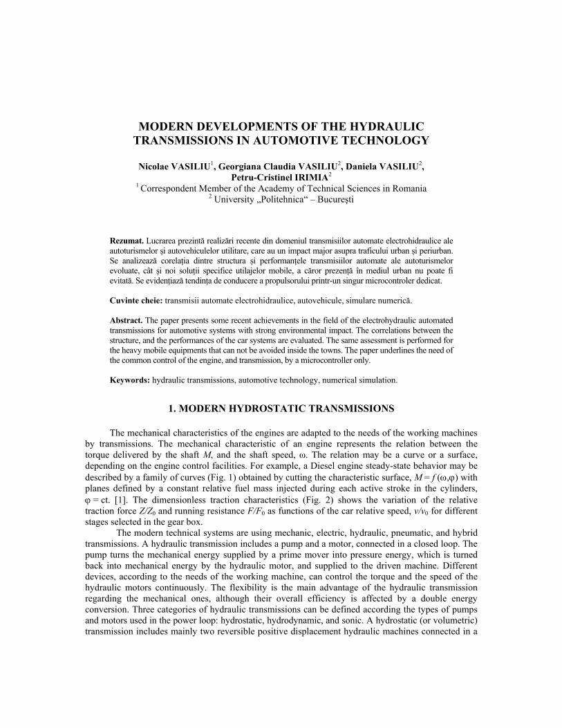
The mechanical characteristics of the engines are adapted to the needs of the working machines by transmissions. The mechanical characteristic of an engine represents the relation between the torque delivered by the shaft M, and the shaft speed, ω. The relation may be a curve or a surface, depending on the engine control facilities. For example, a Diesel engine steady-state behavior may be described by a family of curves (Fig. 1) obtained by cutting the characteristic surface, M = f (,) with planes defined by a constant relative fuel mass injected during each active stroke in the cylinders, = ct. [1]. The dimensionless traction characteristics (Fig. 2) shows the variation of the relative traction force Z/Z0 and running resistance F/F0 as functions of the car relative speed, v/v0 for different stages selected in the gear box.
The modern technical systems are using mechanic, electric, hydraulic, pneumatic, and hybrid transmissions. A hydraulic transmission includes a pump and a motor, connected in a closed loop. The pump turns the mechanical energy supplied by a prime mover into pressure energy, which is turned back into mechanical energy by the hydraulic motor, and supplied to the driven machine. Different devices, according to the needs of the working machine, can control the torque and the speed of the hydraulic motors continuously. The flexibility is the main advantage of the hydraulic transmission regarding the mechanical ones, although their overall efficiency is affected by a double energy conversion. Three categories of hydraulic transmissions can be defined according the types of pumps and motors used in the power loop: hydrostatic, hydrodynamic, and sonic. A hydrostatic (or volumetric) transmission includes mainly two reversible positive displacement hydraulic machines connected in a
C. Amenajări tehnice 341
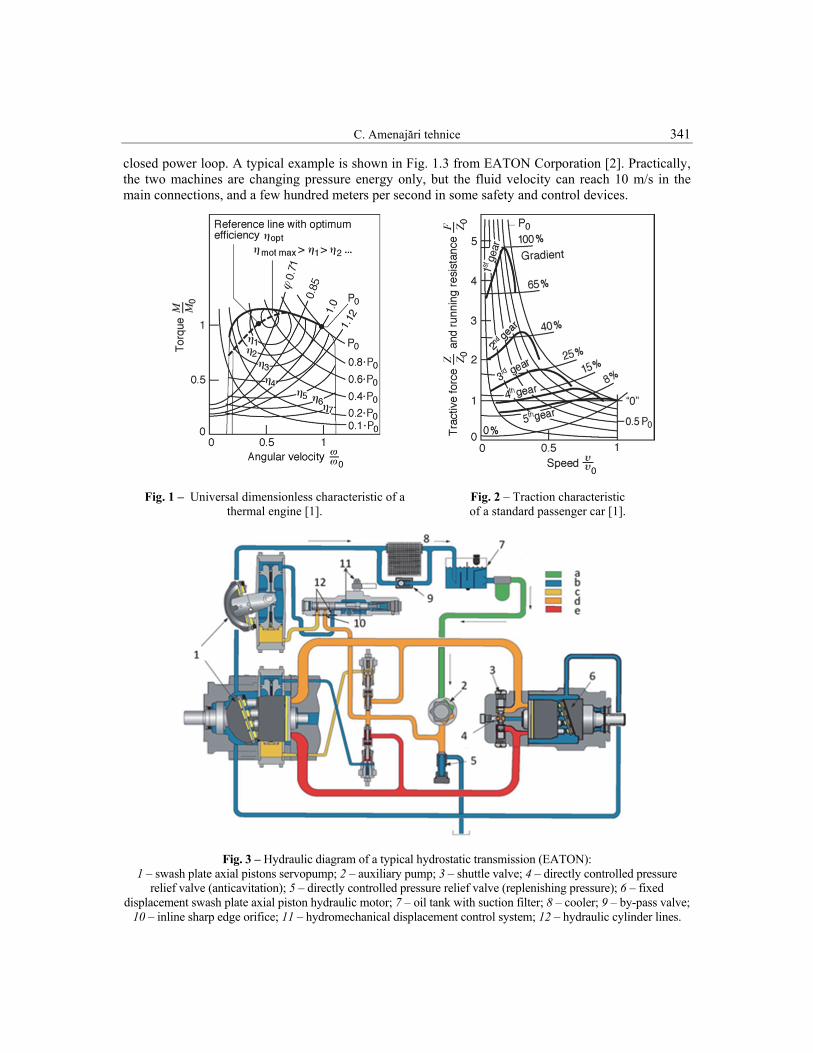
closed power loop. A typical example is shown in Fig. 1.3 from EATON Corporation [2]. Practically, the two machines are changing pressure energy only, but the fluid velocity can reach 10 m/s in the main connections, and a few hundred meters per second in some safety and control devices.
Fig. 1 – Universal dimensionless characteristic of a thermal engine [1].
Fig. 2 – Traction characteristic of a standard passenger car [1].
Fig. 3 – Hydraulic diagram of a typical hydrostatic transmission (EATON): 1 – swash plate axial pistons servopump; 2 – auxiliary pump; 3 – shuttle valve; 4 – directly controlled pressure
relief valve (anticavitation); 5 – directly controlled pressure relief valve (replenishing pressure); 6 – fixed displacement swash plate axial piston hydraulic motor; 7 – oil tank with suction filter; 8 – cooler; 9 – by-pass valve;
10 – inline sharp edge orifice; 11 – hydromechanical displacement control system; 12 – hydraulic cylinder lines.
342 Lucrările celei de-a VII-a ediţii a Conferinţei anuale a ASTR
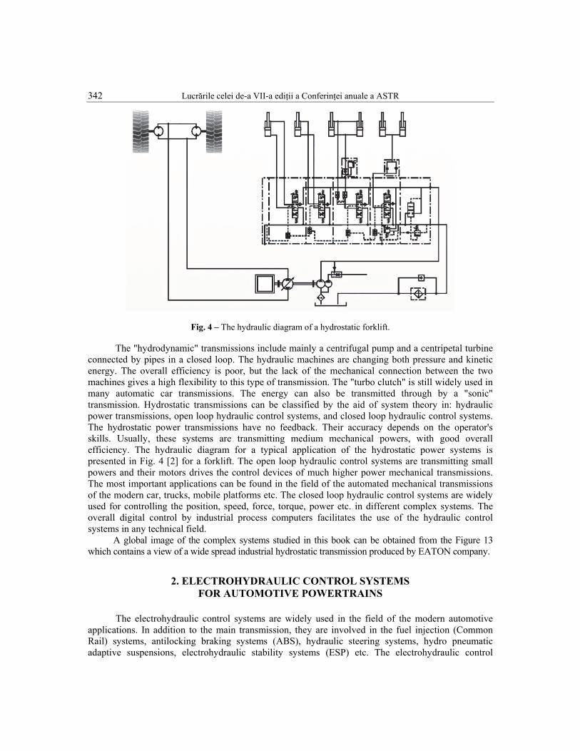
Fig. 4 – The hydraulic diagram of a hydrostatic forklift.
The "hydrodynamic" transmissions include mainly a centrifugal pump and a centripetal turbine connected by pipes in a closed loop. The hydraulic machines are changing both pressure and kinetic energy. The overall efficiency is poor, but the lack of the mechanical connection between the two machines gives a high flexibility to this type of transmission. The "turbo clutch" is still widely used in many automatic car transmissions. The energy can also be transmitted through by a "sonic" transmission. Hydrostatic transmissions can be classified by the aid of system theory in: hydraulic power transmissions, open loop hydraulic control systems, and closed loop hydraulic control systems. The hydrostatic power transmissions have no feedback. Their accuracy depends on the operator's skills. Usually, these systems are transmitting medium mechanical powers, with good overall efficiency. The hydraulic diagram for a typical application of the hydrostatic power systems is presented in Fig. 4 [2] for a forklift. The open loop hydraulic control systems are transmitting small powers and their motors drives the control devices of much higher power mechanical transmissions. The most important applications can be found in the field of the automated mechanical transmissions of the modern car, trucks, mobile platforms etc. The closed loop hydraulic control systems are widely used for controlling the position, speed, force, torque, power etc. in different complex systems. The overall digital control by industrial process computers facilitates the use of the hydraulic control systems in any technical field.
A global image of the complex systems studied in this book can be obtained from the Figure 13 which contains a view of a wide spread industrial hydrostatic transmission produced by EATON company.
2. ELECTROHYDRAULIC CONTROL SYSTEMS FOR AUTOMOTIVE POWERTRAINS
The electrohydraulic control systems are widely used in the field of the modern automotive applications. In addition to the main transmission, they are involved in the fuel injection (Common Rail) systems, antilocking braking systems (ABS), hydraulic steering systems, hydro pneumatic adaptive suspensions, electrohydraulic stability systems (ESP) etc. The electrohydraulic control
C. Amenajări tehnice 343
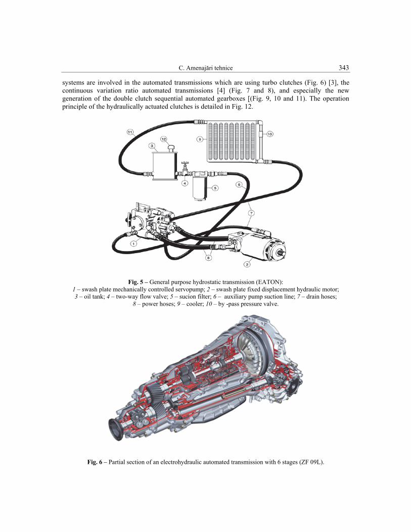
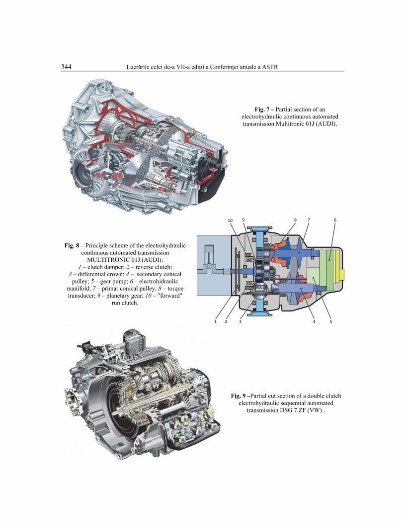
systems are involved in the automated transmissions which are using turbo clutches (Fig. 6) [3], the continuous variation ratio automated transmissions [4] (Fig. 7 and 8), and especially the new generation of the double clutch sequential automated gearboxes [(Fig. 9, 10 and 11). The operation principle of the hydraulically actuated clutches is detailed in Fig. 12.
Fig. 5 – General purpose hydrostatic transmission (EATON): 1 – swash plate mechanically controlled servopump; 2 – swash plate fixed displacement hydraulic motor; 3 – oil tank; 4 – two-way flow valve; 5 – sucion filter; 6 – auxiliary pump suction line; 7 – drain hoses;
8 – power hoses; 9 – cooler; 10 – by -pass pressure valve.
Fig. 6 – Partial section of an electrohydraulic automated transmission with 6 stages (ZF 09L).
344 Lucrările celei de-a VII-a ediţii a Conferinţei anuale a ASTR
Fig. 7 – Partial section of an
electrohydraulic continuous automated transmission Multitronic 01J (AUDI).
Fig. 8 – Principle scheme of the electrohydraulic continuous automated transmission
MULTITRONIC 01J (AUDI): 1 – clutch damper; 2 – reverse clutch;
3 – differential crown; 4 – secondary conical pulley; 5 – gear pump; 6 – electrohidraulic
manifold; 7 – primar conical pulley; 8 – torque transducer; 9 – planetary gear; 10 – "forward"
run clutch.
Fig. 9 –Partial cut section of a double clutch electrohydraulic sequential automated
transmission DSG 7 ZF (VW) .
C. Amenajări tehnice 345
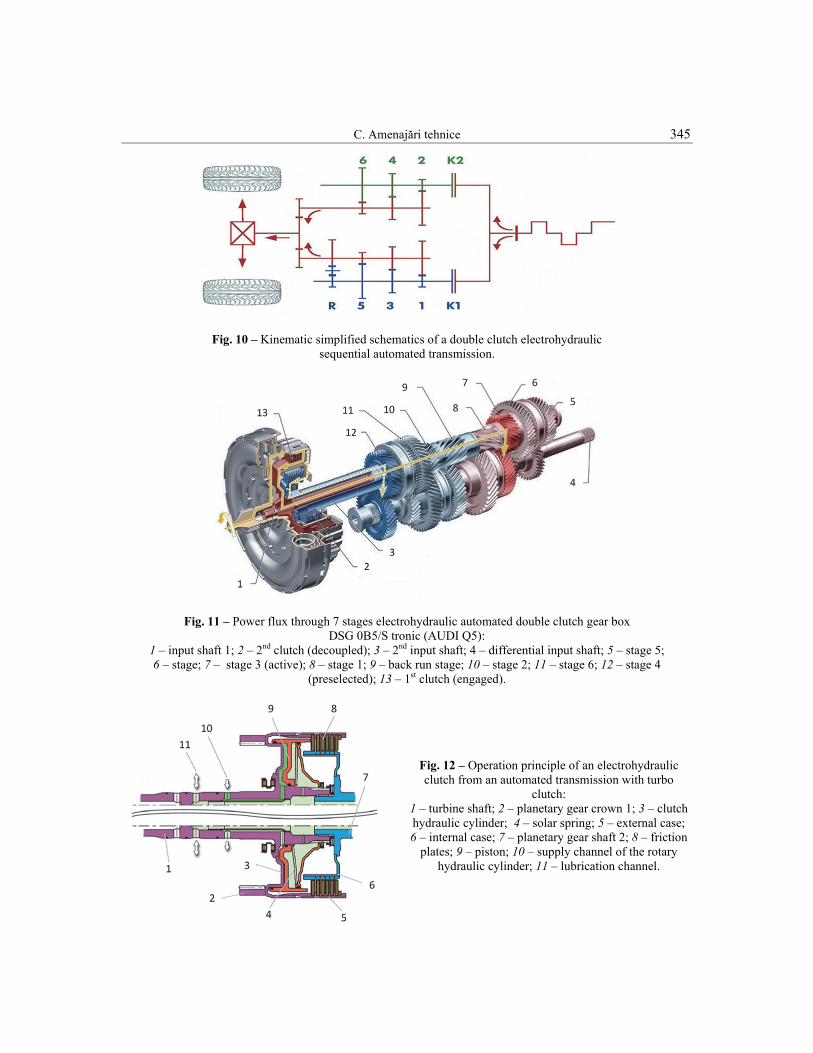
Fig. 10 – Kinematic simplified schematics of a double clutch electrohydraulic
sequential automated transmission.
Fig. 11 – Power flux through 7 stages electrohydraulic automated double clutch gear box DSG 0B5/S tronic (AUDI Q5):
1 – input shaft 1; 2 – 2nd clutch (decoupled); 3 – 2nd input shaft; 4 – differential input shaft; 5 – stage 5; 6 – stage; 7 – stage 3 (active); 8 – stage 1; 9 – back run stage; 10 – stage 2; 11 – stage 6; 12 – stage 4
(preselected); 13 – 1st clutch (engaged).
Fig. 12 – Operation principle of an electrohydraulic clutch from an automated transmission with turbo
clutch: 1 – turbine shaft; 2 – planetary gear crown 1; 3 – clutch hydraulic cylinder; 4 – solar spring; 5 – external case; 6 – internal case; 7 – planetary gear shaft 2; 8 – friction
plates; 9 – piston; 10 – supply channel of the rotary hydraulic cylinder; 11 – lubrication channel.

346 Lucrările celei de-a VII-a ediţii a Conferinţei anuale a ASTR
Fig. 13 – Electrohydraulic control system of the automated transmission SMG Drivelogic for BMW Series 3 cars.
A synthetic image of the electrohydraulic automated sequential transmissions for automotive
applications is presented in Fig. 13 [7]. Electrohydraulic constant pressure supply rotary and linear servomechanisms are used both for clutch drive and stages changes.
3. INNOVATIONS IN ELECTROHYDRAULIC TRANSMISSIONS
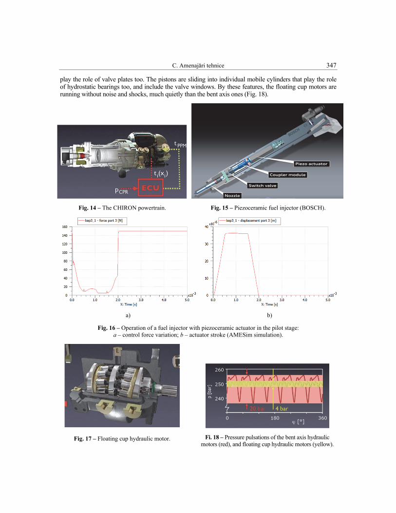
In the last decade, the technical innovation generated new principles and designs in the field of the hydrostatic transmissions. The most important innovation can be considered the joint of a linear ballistic compression ignition engine and a linear positive displacement pump by INNAS BV Company [8] (Fig.14). The new assembly was called „CHIRON FREE PISTON ENGINE”, and it was experimentally set up in a forklift. The thermal engine allows a high flexibility granted by the variable compression degree controlled by a set of high-speed proportional valves, and by the real time control of the fuel injection with a BOSCH piezoceramic injector. The piezoceramic actuators can reach high frequencies (about 50 kHz), but the forces and the strokes developed are relatively low.
Some companies as PARKER and FESTO developed direct drive piezoceramic servovalves for small power pneumatic drives. In the field of electrohydraulic control systems, the most important application of the piezoceramic actuators is the double stage fuel injection servovalve (Fig. 15) developed by BOSCH and other innovative companies for EURO 5 Diesel engines. The results of a numerical simulation with AMESim software [9] (Fig.16) show a very high dynamics: a typical actuator develop a force of about 140 N in 0.6 ms for stroking a conical poppet pilot valve by 40 µm under a pressure difference of about 1800 bar!
The powertrain includes two bladder-type accumulators, which allow the constant pressure supply of the electrohydraulic proportional valves that control all the hydraulic motors. The overall performances of the above powertrain are improved by the high dynamic qualities of a new type of hydraulic motors called floating cup motors (Fig.17). The 22 pistons are working on two rows against two-inclined fixed disk that
C. Amenajări tehnice 347
play the role of valve plates too. The pistons are sliding into individual mobile cylinders that play the role of hydrostatic bearings too, and include the valve windows. By these features, the floating cup motors are running without noise and shocks, much quietly than the bent axis ones (Fig. 18).
Fig. 14 – The CHIRON powertrain. Fig. 15 – Piezoceramic fuel injector (BOSCH).
a) b)
Fig. 16 – Operation of a fuel injector with piezoceramic actuator in the pilot stage: a – control force variation; b – actuator stroke (AMESim simulation).
Fig. 17 – Floating cup hydraulic motor.
Fi. 18 – Pressure pulsations of the bent axis hydraulic motors (red), and floating cup hydraulic motors (yellow).
348 Lucrările celei de-a VII-a ediţii a Conferinţei anuale a ASTR
The most important scientific problem regarding the hydrostatic transmissions is the optimal implementation in complex control systems, using mathematical modeling, numerical simulation, identification, and real time simulation.
The first practical objective of the researches is the significant reduction of both fuel consumption and the pollutant emissions level by the common digital control of the thermal engine and the hydrostatic transmissions, with distributed microcontrollers, interconnected by CAN or other digital bus. This target can be reached by detailed dynamic analysis of all the components only, using modern theoretical and experimental procedures.
4. CONCLUSIONS
The last generation of automotive powertrain strongly depends on the last achievements in the field of the electrohydraulic control systems. An important progress is expected now in the hybrid automotive developments, in close connection with the power electronics. A realistic approach of the electric batteries management shows the need of a effective "marriage" between the hydraulic transmissions and other types of transmissions controlled by CAN systems in an integrated manner [10..15]. The main research direction in the field of the thermal powertrains remains the overall optimization of the engine operation, and the automatic transmission operation by the aid of a single electronic control unit.
References
1. *** Automotive Handbook, 7th Edition, Robert Bosch GmbH, 2007. 2. www.eaton.com 3. www.zf.com 4. www.audi.com 5. www.lmsintl.com 6. www.boschrexroth.com 7. www.bmw.com 8. www.innas.com 9. *** LMS Imagine. Lab Amesim Rev.10. Roanne, 2012. 10. Vasiliu, G.C., Researches on the dynamics of the hydrostatic Transmissions, PhD Thesis, University
Politehnica of Bucharest, 2011. 11. Bătaus M., Vasiliu D., Vasiliu N., Real-Time Simulation of Automated Mechanical Transmissions, The
European Multidisciplinary Society for Modeling and Simulation Technology Conference ESM’2011, 24-26 October 2011, Guimares, Portugal, p.168-174, Eurosis-ETI Publications, ISBN: 978-90-77381-66-3.
12. Vasiliu N., Vasiliu D., Calinoiu C., Manea I. – Modeling and Simulation of the Biofuel Electro Hydraulic Injection Systems by AMESIM. 2010 European Simulation and Modeling Conference ESM’2010, 25-27 October 2010, Hasselt University, Belgium, EUROSYS-ETI Publication, ISBN: 978-90-77381-57-1.
13. Croitorescu V., Anthonis J, Vasiliu N., Thermal Modeling of an electric Motor used on Road Vehicle Powertrain. Industrial Simulation Conference ISC’2012, June 4-6, BRNO, Brno University of Technology, Czech Republic, p.223-231, EUROSYS-ETI Publication, ISBN: 978-90-77381-71-7.
14. Dragne F.D., Alirand M., Oprean I.M., Vasiliu N., ABS Valve Model Reduction by AMESim, Proceedings of the Romanian Academy, Series A - Mathematics Physics, Technical Sciences, Information Science, 1454-9069, May-Aug 2009, Vol. 10, Issue 2.
15. Irimia, P.C., Researches on the Energy Management of the Automotive Systems, PhD Thesis, University Politehnica of Bucharest, 2012.