tom 55(69), fascicola 1, 2010 structure … jumanca.pdf1 faculty of hydrotechnical engineering from...
TRANSCRIPT
1 Faculty of Hydrotechnical Engineering from Timisoara, Water Developments & Land Reclamation and Improvement Dep., Str. George Enescu nr. 1/A, 300022 Timisoara, e-mail: [email protected]
117
Buletinul Ştiinţific al Universităţii "POLITEHNICA" din Timişoara
Seria HIDROTEHNICATRANSACTIONS on HYDROTECHNICS
Tom 55(69), Fascicola 1, 2010
STRUCTURE CALCULATION FOR THE CONCRETE BRIDGE OVER THE RUSCA DAM SPILLWAY GAP ON
RAUL RECE
Radu Lorin JUMANCA 1 Serban-Vlad NICOARA 1
Abstract – The paper presents a structure analysis regarding a concrete passage over a specific hydraulic discharger. The structure approach, following a previous hydrotechnical design, was performed by the help of dedicated software ROBOT v.7. Even if the structure complexity is not very high and the output is in the expected direction, still the approaching method shows all the advantages related to the digital analysis: simple but very coverable modeling, fast run, detailed results of high precision with a representative interface, possibility of design improving. The presented subject is part of a complex project concerning the hydrotechnical development of Rusca Dam on Raul Rece, Caras Severin, part of the “Bistra - Poiana Marului – Ruieni -Poiana Rusca” Hydropower System accomplished by the paper first author.Key words: spillway bridge, structure, numerical modeling, stress and strain state.
1. GENERAL VIEW
The hydroelectric system “Bistra - Poiana Mărului -Ruieni - Poiana Ruscă” provides the development in power for complex purposes of the upper hydrographic basin of Timiş River. From the various developments that form the hydroelectric system “Bistra - Poiana Mărului - Ruieni - Poiana Ruscă” the Poiana Rusca Dam is the subject of this article. “Poiana Rusca” - a concrete arch dam, was originally designed for a height of 95m, but then re-designed and executed with a total height of 75m.However this article concerns a trial version of the dam in which its height is 85m (established based ona calculation of flood wave attenuation and maximum wave height plus safety height).The normal retention level required to be at 640.00 m above the sea level, the top arch was fixed at 645.00 m above the sea level. Minimum level of the dam foundation was established at 560.00 m above the see level, crown arc length is 254.00 m, width at the base 21.50 m and crown width 5.0 m.The evacuation of high water, ice and floats, is made through a spillway with three gaps of a length of 30.9 m. Considering the flow with probability of exceeding 0.1% valued at 424 m 3 / s, the maximum discharged overflow of 286.55 m 3 / s was obtained at
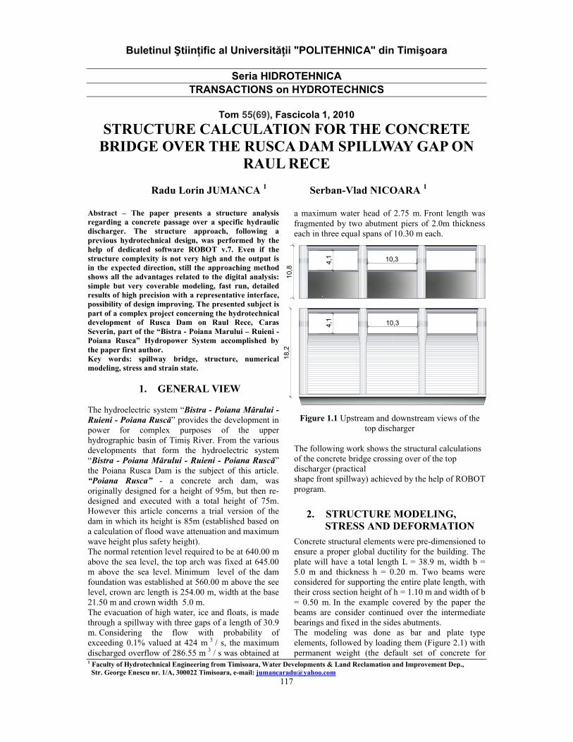
a maximum water head of 2.75 m. Front length was fragmented by two abutment piers of 2.0m thicknesseach in three equal spans of 10.30 m each.
Figure 1.1 Upstream and downstream views of thetop discharger
The following work shows the structural calculations of the concrete bridge crossing over of the top discharger (practical shape front spillway) achieved by the help of ROBOT program.
2. STRUCTURE MODELING, STRESS AND DEFORMATION
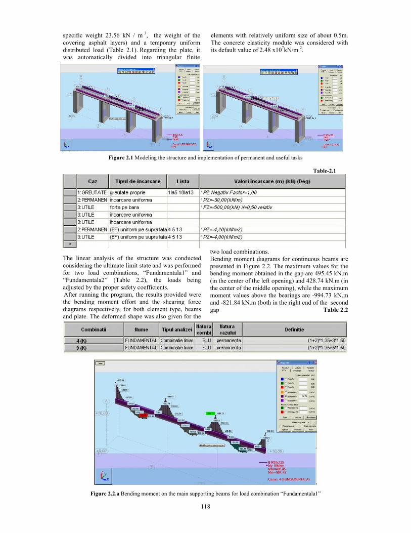
Concrete structural elements were pre-dimensioned to ensure a proper global ductility for the building. The plate will have a total length L = 38.9 m, width b = 5.0 m and thickness h = 0.20 m. Two beams were considered for supporting the entire plate length, with their cross section height of h = 1.10 m and width of b = 0.50 m. In the example covered by the paper the beams are consider continued over the intermediatebearings and fixed in the sides abutments.The modeling was done as bar and plate type elements, followed by loading them (Figure 2.1) with permanent weight (the default set of concrete for
10,
8
10,34,1
4,1 10,3
18,
2
118
specific weight 23.56 kN / m 3, the weight of the covering asphalt layers) and a temporary uniform distributed load (Table 2.1). Regarding the plate, it was automatically divided into triangular finite
elements with relatively uniform size of about 0.5m.The concrete elasticity module was considered with its default value of 2.48 x10⁷kN/m 2.
Figure 2.1 Modeling the structure and implementation of permanent and useful tasks Table-2.1
The linear analysis of the structure was conducted considering the ultimate limit state and was performed for two load combinations, “Fundamentala1” and “Fundamentala2” (Table 2.2), the loads being adjusted by the proper safety coefficients.After running the program, the results provided were the bending moment effort and the shearing force diagrams respectively, for both element type, beams and plate. The deformed shape was also given for the
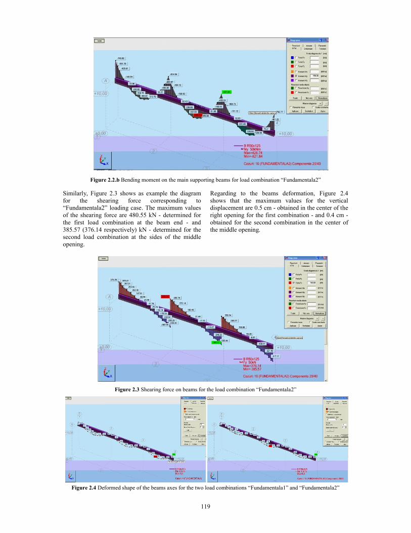
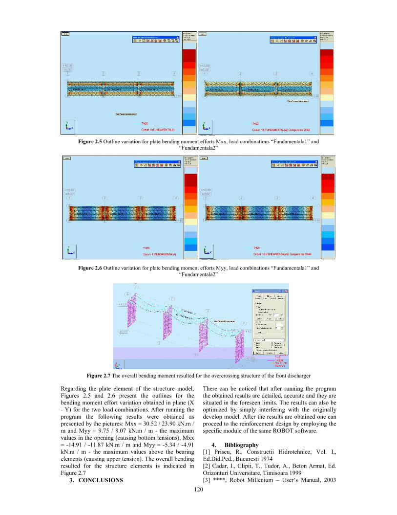
two load combinations.Bending moment diagrams for continuous beams are presented in Figure 2.2. The maximum values for the bending moment obtained in the gap are 495.45 kN.m (in the center of the left opening) and 428.74 kN.m (in the center of the middle opening), while the maximummoment values above the bearings are -994.73 kN.m and -821.84 kN.m (both in the right end of the second gap Table 2.2
Figure 2.2.a Bending moment on the main supporting beams for load combination “Fundamentala1”
119
Figure 2.2.b Bending moment on the main supporting beams for load combination “Fundamentala2”
Similarly, Figure 2.3 shows as example the diagram for the shearing force corresponding to “Fundamentala2” loading case. The maximum valuesof the shearing force are 480.55 kN - determined forthe first load combination at the beam end - and385.57 (376.14 respectively) kN - determined for the second load combination at the sides of the middle opening.
Regarding to the beams deformation, Figure 2.4 shows that the maximum values for the vertical displacement are 0.5 cm - obtained in the center of the right opening for the first combination - and 0.4 cm -obtained for the second combination in the center of the middle opening.
Figure 2.3 Shearing force on beams for the load combination “Fundamentala2”
Figure 2.4 Deformed shape of the beams axes for the two load combinations “Fundamentala1” and “Fundamentala2”
120
Figure 2.5 Outline variation for plate bending moment efforts Mxx, load combinations “Fundamentala1” and “Fundamentala2”
Figure 2.6 Outline variation for plate bending moment efforts Myy, load combinations “Fundamentala1” and “Fundamentala2”
Figure 2.7 The overall bending moment resulted for the overcrossing structure of the front discharger
Regarding the plate element of the structure model, Figures 2.5 and 2.6 present the outlines for thebending moment effort variation obtained in plane (X - Y) for the two load combinations. After running the program the following results were obtained aspresented by the pictures: Mxx = 30.52 / 23.90 kN.m / m and Myy = 9.75 / 8.07 kN.m / m - the maximum values in the opening (causing bottom tensions), Mxx = -14.91 / -11.87 kN.m / m and Myy = -5.34 / -4.91 kN.m / m - the maximum values above the bearingelements (causing upper tension). The overall bending resulted for the structure elements is indicated in Figure 2.7
3. CONCLUSIONS
There can be noticed that after running the program the obtained results are detailed, accurate and they are situated in the foreseen limits. The results can also be optimized by simply interfering with the originally develop model. After the results are obtained one can proceed to the reinforcement design by employing the specific module of the same ROBOT software.
4. Bibliography[1] Priscu, R., Constructii Hidrotehnice, Vol. I,, Ed.Did.Ped., Bucuresti 1974[2] Cadar, I., Clipii, T., Tudor, A., Beton Armat, Ed. Orizonturi Universitare, Timisoara 1999[3] ****, Robot Millenium – User’s Manual, 2003
