petrom omv norm b 2001 rom eng rev.1 2006-12-21
DESCRIPTION
2001bTRANSCRIPT
C U P T O A R E Concept si realizare
Norma Petrom OMV
B 2001 Pag.1
F U R N A C E S Design and Implementation
Petrom OMV Standard
B 2001
Elaborat/ Compiled:
Cibanu Petre
Verificat/ Checked:
Decusara Felicia
Rev:1/21.12.2006 Eng:1/21.12.2006
Aprobat/ Approved:
Jeffrey Rinker
Divizia Rafinare Petrom OMV isi rezerva toate drepturile asupra acestei documentatii si va da in judecata pe orice persoana neautorizata sa o utilizeze sau sa o transmita la terti
Petrom OMV Refining Division reserves all its rights to these documents and will take legal action against anyone using them or passing them on without authorization.
Aceasta norma a fost elaborata pentru rafinariile Petrom prin prelucrarea si adaptarea normei OMV B 2001 rev.1.05.2001
This norm was elaborated for Petrom refineries by the processing and adapting of norm OMV B 2001 rev.01.05.2001
Punct C U P R I N S Pag Point Content Page
GENERALITATI
1.0 3 1.0 GENERAL 3 1.1 Domeniul de validitate 3 1.1 Scope 3 1.2 Norme si proceduri 3 1.2 Standards and instructions 3 2.0 CUPRINSUL NORMELOR 3 2.0 SCOPE OF THE STANDARD 3 3.0 PRINCIPII DE BAZA DIMENSIONARE
CUPTOARE 4 3.0 PRINCIPLES OF FURNACE DESIGN 4
3.1 Informatii generale 4 3.1 General 4 3.2 Tipuri constructive de cuptoare 4 3.2 Furnace Design Types 5 4.0 PREZENTARE DETALII 6 4.0 DETAILED DESIGN 6 4.1 Gradul de eficienta al cuptoarelor 6 4.1 Furnace efficiency 6 4.2 Sarcina maxima admisa pentru suprafata
de incalzire 7 4.2 Permissible heating surface load 7
5.0 TEMPERATURA MAXIMA A PERETILOR TEVII (Calculatie)
8 5.0 MAXIMUM TUBE WALL TEMPERATURE (Calculation)
8
6.0 TUBULATURA 9 6.0 TUBE SYSTEM 9 6.1 Materiale 9 6.1 Materials 9 6.2 Dimensionare tevi 11 6.2 Tube design 11 6.3 Procedee de sudura si verificarea
imbinarilor sudate 12 6.3 Welding and weld seam inspections
12 6.4 Intrari/Iesiri 13 6.4 Inlets and outlets 13 6.5 Suporti de teava 15 6.5 Tube supports 15 6.6 Probe hidrostatice 16 6.6 Pressure tests 16 7.0 ARZATOARE 17 7.0 BURNERS 17 7.1 Dimensionare arzatoare 17 7.1 Burner design 17 7.2 Pozitionare arzatoare 18 7.2 Burner arrangement 18 7.3 Executia arzatoarelor 19 7.3 Burner manufacture 19 7.4 Accesorii pentru arzatoare 22 7.4 Burner accessories 22 7.5 Norme si proceduri 22 7.5 Standards and instructions 22 7.6 Protectie fonica 23 7.6 Noise protection 23 7.7 Suflante, canale de aer 23 7.7 Blowers, air ducts 23 7.8 Arzator aprindere/arzatoare pilot 25 7.8 Ignition burners / pilot burners 25 7.9 Armaturi 26 7.9 Fittings and valves 26 7.10 Vedere de ansamblu asupra instrumentelor
de masurare si control 26 7.10 Overview of the measurement and control
equipment 26 8.0 CONSTRUCTII DIN OTEL 30 8.0 STEEL STRUCTURE 30 8.1 Norme si calcule 30 8.1 Standards and calculation 30
Pag /Page Norma Petrom OMV B 2001 / Petrom OMV Standard B 2001 2
8.2 Platforme, trepte si scari 31 8.2 Platforms, stairs and ladders 30 8.3 Realizare 32 8.3 Implementation 32 8.4 Canale pentru gazul de ardere, cosurile 34 8.4 Smoke exhaust ducts, chimneys 34 8.5 Clapete de reglare a debitului gazului de
ardere 36 8.5 Smoke exhaust butterfly valves 36
8.6 Racord de masurare si racord pentru aburul de stingere
37 8.6 Measurement and extinguishing steam connections
37
8.7 Protectie anticoroziva, acoperire 37 8.7 Corrosion protection, coating 37 9.0 ARMATURI 40 9.0 FITTINGS 40 9.1 Vizoare de inspectie 40 9.1 Inspection openings 40 9.2 Clapete de explozie 40 9.2 Explosion flaps 40 9.3 Usi de vizitare 40 9.3 Entrance doors 40 9.4 Vizoare, usi de vizitare si clapete
antiexplozie 41 9.4 Inspection openings, explosion flaps and
entrance doors 41 10.0 INVELIS TERMOIZOLANT SI
REFRACTAR, IZOLATIE 41 10.0 REFRACTORY LINING, INSULATION 41
10.1 Structura si realizare 41 10.1 Structure and implementation 41 10.2 Zidirea 43 10.2 Brick lining 43 10.3 Mase stampate 44 10.3 Monolithic lining materials 44 10.4 Protectie fonica 46 10.4 Noise protection 46 10.5 Fibre ceramice 46 10.5 Ceramic fibers 46 10.6 Izolatie exterioara 47 10.6 Ceramic fibers 47 11.0 PREINCALZIRE AER 47 11.0 AIR PREHEATERS 47 11.1 Informatii generale 47 11.1 General 47 11.2 Sistem de preincalzire a aerului cu abur 48 11.2 Steam-heated air preheaters 48 11.3 Sistem de preincalzire a aerului cu gaz de
ardere48 11.3 Smoke exhaust air preheater 48
12.0 SUFLANTE DE CENUSA 50 12.0 SOOT BLOWERS 50 13.0 MONTAJ 51 13.0 INSTALLATION 51 14.0 VERIFICAREA SI RECEPTIA
LUCRARILOR DE CONSTRUCT51 14.0 CONSTRUCTION AND ACCEPTANCE
INSPECTIONS51
14.1 Nivelul verificarilor 53 14.1 Inspection scope 53 14.2 Certificate de materiale 54 14.2 Material certifications 53 14.3 Verificarea lucrarilor de santier de catre
Petrom OMV 55 14.3 Construction inspections by
Petrom OMV 54 14.4 Receptii ale autoritatilor 56 14.4 Official acceptance inspections 56 15.0 GARANTII 56 15.0 GUARANTEES 56 15.1 Garantia pentru echipamentul mecanic 56 15.1 Guarantee for mechanical implementation 56 15.2 Garantia de performanta 57 15.2 Performance guarantee 57 15.3 Garantia randamentului 58 15.3 Efficiency guarantee 58 16.0 INDICATII PENTRU PRELUCRAREA
OFERTELOR SI A COMENZII59 16.0 NOTES ON OFFER AND ORDER
PROCESSING 59
16.1 Continutul ofertei 59 16.1 Offer scope 59 16.2 Liste de furnizori 59 16.2 Supplier lists 59 16.3 Fisa tehnica a cuptorului 60 16.3 Furnace data sheet 60 16.4 Corespondenta scrisa 60 16.4 Written correspondence 60 16.5 Aprobarea desenelor 61 16.5 Approval of drawings 61 16.6 Documentatia de productie 62 16.6 Manufacturing documents 62 17.0 PUNEREA IN FUNCTIUNE 62 17.0 COMMISSIONING 62 Anexa 1 - Norme si proceduri 63 Annex 1 - Standards and regulations 63 Anexa 2 - Tipuri constructive de cuptoare 72 Annex 2 - Furnace designs 72 Anexa 3 - Tabel – Incarcarea medie
acceptata pe suprafata de incalzire Annex 3 - Table – Average permissible
load on heating surface

Norma Petrom OMV B 2001 / Petrom OMV Standard B 2001 Pag / Page 3
1.0 INFORMATII GENERALE 1.0 GENERAL 1.1 Domeniu de validitate 1.1 Scope
Aceasta norma este valabila in cadrul rafinariilor Petrom OMV si contine cerinte generale pentru cuptoare.
This OMV standard is valid within Petrom OMV Aktiengesellschaft and contains the general requirements for furnaces.
1.2 Norme si proceduri 1.2 Standards and instructions Impreuna cu prezenta norma se vor respecta dispozitiile, normele si directivele valabile in Romania, in varianta lor aflata in vigoare, care sunt mentionate in Anexa 1.
Nu consideram enumerarea noastra ca fiind una completa.Daca intre diferitele dispozitii, reglementari, norme si directive apar diferente sau contradictii, iar aspectele respective nu sunt in mod expres clarificate prin prezenta norma, se va aplica reglementarea cu formularea cea mai restrictiva.
In cazul in care prevederile se exclud reciproc, atunci se va aplica reglementarea prevazuta de legislatia din Romania. Intra in responsabilitatea executantului sa verifice daca prevederile prezentei norme sunt adecvate scopului lucrarii respective. Aplicarea normei nu il degreveaza pe executant de raspunderea pe care o are in calitate de antreprenor profesionist si responsabil. Daca executantul are obiectii cu privire la una dintre prevederile stabilite, el il va informa imediat in scris pe angajator despre acest lucru.
In conjunction with this Standard, the respective specifications, standards and directives legally applicable in Romania and stated in Annex 1 should be taken into account in their currently valid form.
This listing is not claimed to be complete.
In the event of deviations or conflicts arising between the various specifications, standards and directives and there is no firm definition by this standard, then the strictest formulation is to be applied in each case.
Where they are mutually exclusive, then the
Romanian statutory regulations will apply. The contractor will be responsible for checking
the appropriateness of this standard for the intended purpose. The application does not relieve the contractor of his responsibility as specialist and independent entrepreneur.
If the contractor has reservations concerning an agreed definition, then he must notify the client of this in writing without delay.
2.0 CUPRINS AL NORMELOR
2.0 SCOPE OF THE STANDARD
Aceasta norma include directivele generale pentru conceperea si executarea cuptoarelor de proces in instalatii petrochimice, in special cuptor tubular inclusiv accesorii, cosuri, canale gaze de ardere etc. Pentru cuptoare separatoare termice si catalitice prezenta norma este valabila numai in masura in care nu exista norme special aplicabile pentru componentele sale individuale. In masura in care este aplicabila, aceasta norma este valabila si pentru incalzitoare si generatoare de abur, cu exceptia cazului in care acestea sunt incluse in domeniul de aplicare pentru directiva cazane cu aburi. Alte detalii individuale (ex. Camere de ardere, cuptoare de cracare) sunt reglementate in fisa tehnica.
This standard contains the general guidelines for design and implementation of process furnaces in petrochemical plants, particularly tube furnaces including accessories, chimneys, smoke exhaust channels, etc. For thermal and catalytic steam cracker furnaces, the following regulations apply insofar as no separate standards apply for individual components. Insofar as it is applicable, this standard is also valid for boilers and steam generators, unless these are covered within the scope of the Ordinance on Steam Boilers.
Additional details (e.g. combustion chambers, steam crackers) are regulated in the data sheets.

Pag /Page Norma Petrom OMV B 2001 / Petrom OMV Standard B 2001 4
3.0 PRINCIPII DE BAZA PENTRU DIMENSIONAREA CUPTOARELOR
3.0 PRINCIPLES OF FURNACE DESIGN
3.1 Informatii generale 3.1 General Prestatorul trebuie sa conceapa in mod responsabil si tinand cont de nivelul tehnic de dezvoltare planurile tehnice si mecanice avand la baza specificatiile incluse in fisele tehnice.
Prestatorul trebuie sa propuna o solutie economica si in caz de nevoie, sa faca referiri la datele incluse in fisele tehnice, care nu corespund nivelului actual de dezvoltare tehnica, care sunt neeconomice sau care nu pot fi acceptate din alte motive. In acest caz trebuie sa vina cu propuneri proprii. Urmatoarele reglementari nu il scutesc pe furnizorul unui cuptor de raspunderea sa generala si de oferirea garantiei. Pe langa normele si procedurile indicate in aceste fise de date si in prezenta norma, sunt valabile toate directivele, reglementarile, hotararile si legile romane in acest sens, in versiunea valida la momentul solicitarii ofertei.
3.1.1 Cuptoarele de proces sunt compuse din zona de
radiatie si cea de convectie. Cuptoare pure de radiatie sunt acceptate numai cu aprobare speciala pentru performante mici de incalzire si durata scurta de functionare (de exemplu cuptoare de regenerare) la temperaturi inalte de produs.
3.1.2 Daca modul de functionare si de mentenanta o
permite, un grup de cuptoare poate fi echipat cu o zona comuna de convectie.
3.1.3 Pentru imbunatatirea gradului de eficacitate
termica a cuptorului este posibila instalarea de fascicule de tevi pentru preincalzirea apei de alimentare si/sau generarea de abur in zona de convectie sau in cazanul recuperator separat pentru unul sau mai multe cuptoare impreuna. Pentru cuptoare de putere mare se va verifica o eventuala folosire a sistemlui de preincalzire a aerului, daca nu poate fi atins in alt mod, economic, randamentul specificat.
The contractor must conscientiously perform the technical process-related and mechanical conception and design based on the design data required in the data sheets and in consideration of the state of the art.
The contractor must propose the most
economical solution and refer, if necessary, to requirements in the data sheets that do not conform to the state of the art, are uneconomical or are unacceptable for other reasons. In this case, he must offer his own suggestions.
The following provisions do not relieve the supplier of a furnace of his overall responsibility and guarantee.
In addition to the standards and regulations listed in this standard and the data sheets, all pertinent Romanian regulations, specifications, ordinances and laws as amended at the time of the awarding of the order must be taken into consideration.
3.1.1. Process furnaces consist of radiation and
convection zones. Pure radiation furnaces are only permissible with special approval for low thermal output and short-term operation (e.g. regeneration furnaces) at high product temperatures.
3.1.2. When it is possible with regard to operation and
maintenance, a group of furnaces can be equipped with a shared convection zone.
3.1.3. For improvement of the thermal furnace
efficiency level, the use of tube bundles for supply water preheating and/or steam generation in the convection zone or in the separate waste heat boiler is possible for one or more furnaces together. For furnaces of large thermal output, the use of air preheaters should be evaluated if the specified efficiency cannot be achieved effectively in other ways.
3.2 Tipuri constructive de cuptoare 3.2 Furnace Design Types 3.2.1 Cele mai importante tipuri constructive sunt date
in anexa 2. 3.2.2 De regula, cuptoarele cu tevi verticale in zona de radiatie a caldurii sunt de preferat celor cu tevi pozitionate orizontal.
3.2.3 Cuptoarele rotunde sunt preferate pentru
3.2.1.The most important furnace design types are summarized in annex 2. 3.2.2 Generally, furnaces with vertical tube
arrangements in the radiation zone are preferred to horizontal tubing.
Norma Petrom OMV B 2001 / Petrom OMV Standard B 2001 Pag / Page 5
incalzirea mediilor gazoase si lichide, precum si ca cuptoare de fierbere (vaporizator) pentru sarcini mici si medii. Executare conform anexei 2 fig.1. 3.2.4 Cuptoarele rotunde cu spirale conform anexei 2 fig.2 sunt prevazute doar pentru cazuri speciale – sarcini mici si cerinta pentru posibilitatea
de golire completa sau pierdere minima acceptata de presiune – preferinte care vor fi clar specificate in fisele tehnice. Acest lucru este valabil si pentru cuptoare rotunde cu cilindru de represie, conform anexei 2 fig. 3. Folosirea lor este limitata la cuptoare cu functionare discontinua (de regenerare) sau temperatura mica de productie. In acest caz devine simpla corectarea gradului de eficienta termica.
3.2.5 Pentru randamente mari poate fi propusa si o
structura a cuptorului conform anexei 2, fig. 11 – doua cuptoare rotunde cu zona comuna de convectie.
3.2.6 Cuptoare cutii cu tevi orizontale conform anexei 2
imaginile 4 ,5, si 6. Acest model este depasit din punct de vedere tehnic si mai poate fi folosit doar in cazuri de exceptie (ex. EDC, Visbreaker,....).
3.2.7 Cuptoare conform anexelor 2, fig.4 si 5 pot fi utilate
pentru a corespunde cazurilor speciale mentionate in punctul 3.2.6 – cuptoare cu vid sau cu coate de retur acoperite – conform specificatiilor. Pentru realizarea in mai multe treceri, pozitionarea tevilor trebuie discutata cu managerul de proiect din partea Petrom OMV.
3.2.8 Structura cuptorului conform anexei 2 imaginea 6
este acceptata numai cu aprobarea managerului de proiect Petrom OMV.
3.2.9 Modelele cu tevi pozitionate central orizontal sau vertical si cu arzatoare in pereti si/sau prin arzatore in podea conform anexei 2 imaginea 7, 8 si 9 pot fi folosite cu functia de cuptoare de cracare termice si catalitice si in acelasi timp si pentru alte temperaturi inalte de operare (reformare). Acest model va fi folosit in cazurile, unde este necesara evitarea unei sarcini termice mari asupra tubulaturii sau a produsului.
3.2.10 Pentru cuptoarele moderne de distilare si
pentru alte cuptoare cu performante termice mari, vor fi aplicate de preferinta modelele conform anexei 2 figurile10 si 11, incalzite cu „arzatoare de capacitate mare“.
3.2.11 Cuptoarele cu tevi verticale, arzatoare de sus
si conducta de evacuare a gazului de ardere la baza cuptorului, sunt folosite exclusiv ca si
3.2.3 Circular furnaces are preferred as heaters for gaseous and liquid media, and boiling furnaces (vaporizers) are preferred for low and medium outputs. Design according to annex 2 fig.1.
3.2.4 Circular furnaces with spiral tubing as
perannex 2 fig. 2 are only permissible for special cases – low output and required complete draining capability or low permissible pressure loss – and are specified specially in the data sheet. This also applies to circular furnaces with displacement cylinders as per annex 2 fig. 3. Their use is restricted to furnaces with discontinuous operation (regeneration furnaces) or low product temperature. In this case, improvement of the thermal efficiency is possible and simple.
3.2.5 For large furnace outputs, a furnace design as
per annex 2 fig. 11 may be proposed – two circular furnaces with shared convection zones.
3.2.6 Box furnace with horizontal tube arrangement as per annex 2 fig. 4, 5, and 6. This design is technically outmoded and may only be still be used in special cases (e.g. EDC, visbreaker,....).
3.2.7 Furnaces as per annex 2 fig. 4 and 5 can be
designed according to specification for the special cases listed under item 3.2.6 – vacuum furnace or furnaces with plug return bends. For multi-pass design, the tube arrangement is to be agreed with the Petrom OMV project manager.
3.2.8 Furnace design as per annex 2 fig. 6 is only
permitted upon approval by the Petrom OMV project manager.
3.2.9 Furnace designs with horizontal or vertical tube arrangement and heating through side walls and/or floor burners as per annex 2 fig. 7, 8, 9 are thermal and catalytic cracking furnaces and can be used for other high temperature processes (reformers). This design must be used in those cases in which high thermal loads must be avoided for the tube material or the medium.
3.2.10 For modern byproduct coke furnaces and other furnaces of large thermal output, designs according to annex 2 fig. 10 and 11, heated by “burners with high thermal output,” are preferred.
3.2.11 Furnaces with vertical tubes, ceiling burners

Pag /Page Norma Petrom OMV B 2001 / Petrom OMV Standard B 2001 6
cuptoare de cracare ("Steam-Reformer") catalitice, pentru generarea gazului de sinteza, etc. Aceasta realizare face necesara folosirea exclusiva a arzatoarelor cu aer insuflat.
Forma speciala: cuptoare mici de reformer cu aspiratie naturala de aer sunt folosite numai cu aprobarea speciala a managerului de proiect Petrom OMV.
and smoke exhaust on the furnace floor are used exclusively as catalytic cracking furnaces (“steam reformers”) for production of synthesis gas, etc. This design requires the exclusive use of forced air burners. Special design: small reformer furnaces with natural draft are possible with the approval of the Petrom OMV project manager.
4.0 PREZENTAREA DETALIILOR 4.0 DETAILED DESIGN 4.1 Grad de eficienta a cuptorului 4.1 Furnace efficiency 4.1.1 Pentru gradul de eficienta termica a unui cuptor
respectiv a unui sistem cuptor de proces/ folosirea caldurii reziduale – este indicat sa nu se scada sub urmatoarele valori limita:
La o performanta neta de incalzire a cuptorului de proces de < 5.000.000 kcal/h 6 MW ηtherm = 80%
< 10.000.000 kcal/h 12 MWηtherm =84 % cu preincalzire aer ≥90%
> 10.000.000 kcal/h 12 MWηtherm =89 % preinc. aer ≥90%
Gradul de eficienta trebuie determinat pentru
performanta prevazuta a cuptorului si pentru excedentul de aer planificat pentru tipul de combustibil si de arzator prevazut conform punctului 7.1. Daca un grup de cuptoare este legat intr-o retea de folosire a caldurii reziduale , este valabila suma neta a performantelor termice a tuturor cuptoarelor conectate pentru respectivul factor de eficacitate termica.
4.1.2 Se va include in gradul de eficacitate, in functie de
alegerea producatorului cuptorului, fie o valoare stabila a pierderii radiate de 1,5 % a performantei termice totale, fie o valoare calculata a pierderii prin peretii cuptorului. In cel de-al doilea caz se pleaca de la premisa unor valori de caldura radiata de catre peretii cuptorului conforme valorilor acceptate conform punctului 10.1.5 si a unui factor aditional de siguranta de 20 % adaugat valorii calculate.
4.1.3 Gradul de eficacitate termica este bazat pe
valoarea calorica minima a combustibilului folosit. In cazul combustibilelor mixte, se va stabili de la caz la caz, pentru ce tip de combustibil sa fie proiectat cuptorul.
4.1.1 For the thermal efficiency of a furnace or a system of process furnaces / waste heat utilization, the following minimum values should generally be achieved: For a net thermal output of the process furnace of <5,000,000 kcal/h 6 MW ηtherm = 80% <10,000,000 kcal/h 12 MW ηtherm = 84% with air preheater ≥90% >10,000,000 kcal/h 12 MW ηtherm = 89% with air preheater ≥90%
The efficiency must be determined for the design output of the furnace, and the excess air values upon which the various fuel and burner types of the design are based shall be determined according to item 7.1 of this standard. If a group of furnaces is merged into a system with shared waste heat utilization, the total of the net thermal outputs of all connected furnaces applies for the required total thermal efficiency.
4.1.2 Also to be included in the efficiency calculation, by selection of the furnace manufacturer, is either a flat radiation loss of 1.5% of the gross thermal output or a calculated thermal loss through the furnace walls. In the latter case, the calculation shall be based on the permissible surface temperature of the furnace walls according to item 10.1.5, and a safety margin of 20% shall be added to the calculated value.
4.1.3 The thermal efficiency is based on the lower thermal value of the fuel used. In the case of mixed firings, the fuel for which the furnace must be designed shall be agreed in individual cases.
4.2. Sarcina maxima acceptata pentru suprafata de incalzire
4.2 Permissible heating surface load
Norma Petrom OMV B 2001 / Petrom OMV Standard B 2001 Pag / Page 7
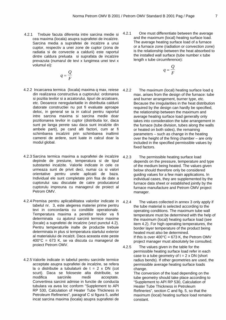
4.2.1 Trebuie facuta diferenta intre sarcina medie si cea maxima (locala) asupra suprafetei de incalzire. Sarcina media a suprafetei de incalzire a unui cuptor, respectiv a unei zone de cuptor (zona de radiatia si de convectie a caldurii) este raportul dintre caldura preluata si suprafata de incalzire prevazuta (numarul de tevi x lungimea unei tevi x volumul ei):
qQF
=
4.2.2 Incarcarea termica (locala) maxima q max, reiese din realizarea constructiva a cuptorului: ordonarea si pozitia tevilor si a arzatorului, tipuri de arzatoare, etc. Deoarece neregularitatile in distributia caldurii datorate constructiei nu pot fi evaluate aproape deloc, in general se ia in calcul pentru raportul intre sarcina maxima si sarcina medie doar pozitionarea tevilor in cuptor (distributia lor, daca sunt pe langa perete sau daca sunt incalzite din ambele parti), pe cand alti factori, cum ar fi schimbarea incalzirii prin schimbarea inaltimii camerei de ardere, sunt luate in calcul doar la modul global.
4.2.3 Sarcina termica maxima a suprafetei de incalzire
depinde de presiune, temperatura si de tipul substantei incalzite. Valorile indicate in cele ce urmeaza sunt de privit deci, numai ca si valori orientative pentru unele aplicatii de baza. Individual ele sunt completate prin fisa de date a cuptorului sau discutate de catre producatorul cuptorulu impreuna cu managerul de proiect al Petrom OMV.
4.2.4 Premisa pentru aplicabilitatea valorilor indicate in
tabelul nr. 3, este alegerea materiei prime pentru tevi in concordanta cu conditiile operationale. Temperatura maxima a peretilor tevilor va fi determinata cu ajutorul sarcinii termice maxime (locale) a suprafetei de incalzire (vezi punctul 4.2). Pentru temperaturile inalte de productie trebuie determinata in plus si temperatura startului exterior al materialului de incalzit. Daca aceasta este peste 400°C = 673 K, se va discuta cu managerul de proiect Petrom OMV.
4.2.5 Valorile indicate in tabelul pentru sarcinile termice acceptate asupra suprafetei de incalzire, se refera la o distributie a tubulaturii de t = 2 x DN (cot scurt). Daca se foloseste alta distributie, se modifica sarcinile medii acceptate. Convertirea sarcinii admise in functie de conducta tubulara va avea loc conform "Supplement to API RP 530, Calculation of Heater Tube Thickness in Petroleum Refineries", paragraf C si figura 5, astfel incat sarcina maxima (locala) asupra suprafetei de
4.2.1 One must differentiate between the average and the maximum (local) heating surface load. The average heating surface load of a furnace or a furnace zone (radiation or convection zone) is the relationship between the heat absorbed to the installed wall surface (tube number x tube length x tube circumference):
qQF
=
4.2.2 The maximum (local) heating surface load q max. arises from the design of the furnace: tube and burner arrangement, burner type, etc. Because the irregularities in the heat distribution required by the design can hardly be specified, the relationship between the maximum and average heating surface load generally only takes into consideration the tube arrangement in the furnace (tube division, tubes along the walls or heated on both sides), the remaining parameters – such as change in the heating over the height of the firing chamber – are only included in the specified permissible values by fixed factors.
4.2.3 The permissible heating surface load
depends on the pressure, temperature and type of the medium being heated. The values given below should therefore only be considered guiding values for a few main applications. In individual cases, they are supplemented by the furnace data sheet or established jointly by the furnace manufacture and Petrom OMV project manager.
4.2.4 The values collected in annex 3 only apply if
the tube material is selected according to the operating conditions. The maximum tube wall temperature must be determined with the help of the maximum (local) heating surface load (see item 4.2). For high operating temperatures, the border layer temperature of the product being heated must also be determined. If this is over 400°C = 673 K, the Petrom OMV project manager must absolutely be consulted.
4.2.5 The values given in the table for the permissible heating surface load refer in each case to a tube geometry of t = 2 x DN (short radius bends). If other geometries are used, the permissible average heating surface loads change. The conversion of the load depending on the tube geometry should take place according to “Supplement to API RP 530, Calculation of Heater Tube Thickness in Petroleum Refineries”, section C and fig. 5, so that the maximum (local) heating surface load remains constant.
Pag /Page Norma Petrom OMV B 2001 / Petrom OMV Standard B 2001 8
incalzire sa ramana constanta.
4.2.6 Valorile acceptate pentru tevi incalzite dintr-o singura parte, asa cum sunt indicate in tabel, sunt pentru tevile care au o distanta fata de perete de 1.5 x diametrul tevii. Sarcina termica medie acceptata pe suprafata de incalzire conform imaginilor din anexa 2, vezi si anexa 3.
4.2.7 In zona tampon respectiv, celor doua randuri de
jos ale zonei de convectie a unui cuptor, sarcina termica medie nu poate fi mai mare decat este indicat in primul rand al tabelului, pentru fiecare produs.
4.2.8 In zona de convectie, sarcina termica medie asupra suprafetei de incalzire pentru teava neteda poate fi pana la 1,8 x a valorilor trecute in primul rand al tabelului.
4.2.6 The permissible values for tubes heated on one side given in the table refer to tubes with a spacing from the wall of 1.5 x tube outer diameter. For permissible average heating surface loads for tube arrangement according to the figures from annex 2, see annex 3.
4.2.7 In the “shield zone” or the bottom two rows of
the convection zone of a furnace, the average heating surface load may not be higher than given in line 1 of the table for the respective use.
4.2.8 In the convection zone, the average heating load
with respect to the smooth tube may equal 1.8 times the values listed in line 1 of the table.
5.0 TEMPERATURA MAXIMA A PERETILOR TEVII (Calcule)
5.0 MAXIMUM TUBE WALL TEMPERATURE (Calculation)
5.1 Temperatura maxima a peretilor tevii, este temperatura maxima (locala). Calcularea acestei temperaturi maxime (locale) are loc conform "Supplement to API RP 530, Calculation of Heater Tube Thickness in Petroleum Refineries ". La temperatura maxima calculata a peretilor, (mod de functionare EOR – sfarsit de reactie catalitica) se va adauga un factor de +15°C (conform API) sau valoarea indicata in fisa tehnica a cuptorului.
5.2 Temperatura calculata in acest mod nu trebuie sa
depaseasca temperatura maxima acceptata a peretilor tevii, temperatura adaptata procesului si materiei prime. Pentru calcularea grosimii peretilor, ea este temperatura luata in considerare ca si baza de calcul, in masura in care fisa tehnica a cuptorului nu specifica o valoare mai mare pentru acest lucru
5.1 The maximum tube wall temperature refers to the maximum (local) temperature that arises. The calculation of this maximum (local) tube wall temperature takes place according to “Supplement to API RP 530, Calculation of Heater Tube Thickness in Petroleum Refineries”. A minimum addition of +15°C (as per API) must be applied to the max.calculated tube wall temperature (operating type EOR) or the value specified in the furnace data sheet used.
5.2 The temperature calculated in this way may not
exceed the permissible tube wall temperature based on the process or material. For the wall thickness temperature, this is the calculated temperature, unless a higher value is specified in the furnace data sheet.
5.3 Suprafete marite 5.3 Enlarged surfaces5.3.1 Extinderea suprafetelor de incalzire este
permisa in zona de convectie cu nervuri sau bolturi.
Nervurile folosite trebuie sa aiba o grosime minima de 1,5 mm si o inaltime maxima de 25 mm. Pentru cuptoare incalzite cu combustibil lichid, nervurile trebuie sa fie amplasate la o distanta de 8 mm intre ele, pentru cuptoare pe gaz la 6 mm.
5.3.2 Insertiile trebuie sa aiba la baza o distanta
minima de 2,5 mm intre ele. 5.3.3 In cazul zonelor de convectie, care sunt
construite direct pe zona de radiatie si supuse astfel radiatiei directe a caldurii din camera de
5.3.1 The enlargement of the heating surfaces in the convection zone with ribbing or studs is permitted. The ribs used should have a minimum thickness of 1.5 mm and a height of max. 25 mm. For oil-fired furnaces, the ribs should have a minimum spacing of 8 mm, for gas-fired furnaces 6 mm.
5.3.2 Studs should have a minimum spacing of 2.5
mm at the base (measured between outer circumferences).
5.3.3 For convection zones that are built directly onto the radiation zone and are therefore subject to radiation from the firing chamber, at

Norma Petrom OMV B 2001 / Petrom OMV Standard B 2001 Pag / Page 9
ardere, cel putin primele trei randuri de tevi de jos vor fi realizate cu tevi netede. Daca zona de convectie este delimitata de zona de radiatie (ex anexa 2 fig.10) aceasta prevedere nu se mai aplica.
5.3.4 Daca in aria de convectie sunt folosite tevi cu suprafata marita, trebuie determinata pentru aceasta situatie temperatura maxima a nervurilor sau temperatura stifturilor. Nervurile sau stifturile din otel carbon pot atinge in cele mai calde puncte valoarea maxima de 450°C , iar tevile cu un continute de 11-13 %otel crom, chiar 560°C. Materiile austenitice nu vor fi folosite pentru extinderea suprafetei.
5.3.5 Viteza masei 5.3.5.1 Planificarea are loc dupa cea diagrama in doua
faze in timpul HTFS (Heat Transfer and Fluid Flow Services / transfer termic si curgere). Daca in decursul acestui procedeu este depasita valoarea limita de pierdere a presiunii, va fi discutata cu managerul de proiect Petrom OMV o posibila reducere a vitezei acestei mase.
5.3.5.2 Baza acestei discutii o va constituii calcularea
pierderii de presiune pentru fluxul in doua faze conform "HTFS". Dupa aceasta se poate dovedi existenta unui flux hidrodinamic dispersat in doua faze.
least the bottom three tube rows must be designed as smooth tubes. If the convection zone is separated from the radiation zone(e.g. annex 2 fig.10), this restriction does not apply.
5.3.4 If tubes with enlarged surfaces are used in
the convection zone, the maximum arising rib or stud temperature must be determined here. Ribs or studs of carbon steel may reach a maximum of 450°C at the hottest point, ribs or studs of 11-13 % chrome steel may reach max. 560°C. Austenitic materials should not be used for surface enlargement.
5.3.5 Mass speed 5.3.5.1 The design take place according to the 2-
phase diagram for HTFS (Heat Transfer and Fluid Flow Services/ thermal transfer and flowing). If the permissible pressure loss is exceeded here, a possible reduction of this mass speed must be discussed with the Petrom OMV project manager.
5.3.5.2 The pressure loss calculation for two-phase
flow according to “HTFS” must be used as the basis for this discussion. Accordingly, verification of a disperse two-phase flow is required.
6.0 TUBULATURA 6.0 TUBE SYSTEM
6.1 Materiale 6.1 Materials 6.1.1 Toate materialele de tubulatura vor fi alese
respectand reglementarile romane valabile in acest sens.
Aliajele speciale si tevile centrifugate vor fi stabilite impreuna cu organismul de verificare.
6.1.2 Pentru echiparea generala a cuptoarelor cu
tevi din metale aliate sau nealiate pot fi folosite valori caracteristice ale materiilor prime conform SEW (Stahl-Eisen-Werkstoffblättern – date tehnice producatori de oteluri).
6.1.3 Sistemele de tubulatura care sunt supuse unei obligatii de aprobare si de monitorizare prin directiva privind functionarea cazanelor sub presiune, vor fi realizate in mod obligatoriu din materiale aprobate de catre autoritatile romane. Sistemele vor fi testate preliminar de catre organismul de verificare. Pentru alte materii prime este necesara obtinerea unei autorizatii speciale, dupa aprobarea obtinuta de la managerul de proiect Petrom OMV.
6.1.4 Ca si tevi de cuptor sau piesele prefabricate
pentru forme sunt acceptate in principiu doar tevi presate la cald, fara imbinari si tevi trase la cald sau la rece. (Caz special: tevile centrifugate).
6.1.1 All tube materials must be selected according to the applicable Romanian regulations.
Special alloys and centrifugally cast tubes must be agreed with the competent initial inspection office.
6.1.2 For general furnace tubing of unalloyed and alloyed tubes, material characteristics values according to steel / iron material data sheets (SEW) can be used.
6.1.3 Tube systems that are subject to official acceptance and monitoring requirements according to the Boiler Act must be made of materials permitted in Romania. The systems must be inspected by the initial inspection office. For other materials, exception approval must be applied for after approval by the Petrom OMV project manager.
6.1.4 Generally only seamless, heat-pressed and
warm- or cold-drawn tubes are permitted as furnace tubes and prefabricated parts for tube fittings (special case: centrifugal casting).
Pag /Page Norma Petrom OMV B 2001 / Petrom OMV Standard B 2001 10
6.1.5 Ca si tevile cu nervuri pentru zona de convectie pot fi folosite doar tevi cu nervuri sudate continuu sau cu nervuri valtuite din peretele tevii. Nervurile pot fi aplicate fie prin procedeul gazului de protectie cu sau fara material de adaos sau prin sudare prin rezistenta. Alte moduri de productie (de reductie, lipirea in baie) nu sunt acceptate.
6.1.6 Toate tevile si piesele turnate vor purta
marcaje clare, din care sa rezulte producatorul, materialul si referinta la certificatele de aprobare relevante (numarul de lot/ sarja sau alte informatii).
Se vor folosi marcaje DIN respectiv denumiri ASTM pentru materii prime, nu denumiri ale producatorului. De regula marcajul trebuie aplicat pe un camp in apropierea unui capat de teava, prin poansonare (cu profil rotunjit) sau prin eroziune cu scantei. Marcajele exclusiv cu vopsea nu sunt acceptate.
Pentru marcarea suplimentara cu culori (punerea in evidenta a campului marcat, marcaje pentru transport, etc) pot fi folosite numai culori care nu contin sulf, zinc, cupru, plumb si halogeni (exceptia: tevi centrifugata).
6.1.7 Tevile si piesele folosite in interiorul cuptorului
vor fi livrate in interior si exterior, dar mai ales in interior fara tunder. Procedura pentru de indepartarea tunderului (baituire, sablare, ardere) va fi decisa de catre producatorul tevilor sau a pieselor. Daca tunderul este indepartat prin baituire, piesele trebuiesc apoi pasivizate. Tevile din oteluri feritice cu mai putin de 13 % Cr vor fi protejate, dupa indepartarea tunderului prin introducerea intr-o baie de combustibil lichid, prin aplicarea unui strat de lac, sau prin alte metode asemanatoare. Capetele fiecarei tevi vor fi sigilate cu capace de plastic.
6.1.5 Only tubes with welded-on ribs running around the full circumference or ribs milled from the tube wall may be used as ribbed tube for the convection zone. The ribs can be welded on either by arc welding with or without welding filler or by resistance welding. Other manufacturing processes (e.g. shrinking on, dip soldering) are not permitted.
6.1.6 All tubes and tube fittings must possess clear
labels, in which the manufacturer, material and association with acceptance inspection documentation (lot number or the like) are clearly emphasized.
The DIN or ASTM designations should be used for material designation, not manufacturer brands. Generally, the label should be placed on a span near the end of a tube with a marking punch (with rounded profile) or by electrical erosion. Markings consisting only of paint are not permitted.
In the case of additional paint markings (emphasizing of the label field, shipping labeling, etc.) only paints that are free of sulfur, tin, copper, lead and halogen may be used (exception: centrifugally cast tubes).
6.1.7 Tubes and tube fittings for furnace tubing
must be delivered free of scales on the inside and should be free of scales on the outside as well. The process for descaling (pickling, sand-blasting, bright annealing) may be selected by the tube or tube fitting manufacturer. If the scale is removed by pickling, the parts must then be passivated. Tubes of ferritic steels with less than 13 % Cr must be protected after descaling by submersion into an oil bath, coating with paint or the like. The ends of all tubes must be sealed with plastic caps.
6.2 Dimensionarea tevilor 6.2 Tube design 6.2.1 Calcularea grosimii peretilor de teava si a
pieselor turnate este efectuata pentru cuptoare, conform directivelor recunoscute in acest sens (de exemplu codul AD 2000 B0, B1, codul ASME ). Este necesara o punere de acord cu managerul de proiect Petrom OMV si cu reprezentantii autoritatii de verificare.
Presiunea si temperatura folosite ca baze pentru calcul sunt stabilite in fisa tehnica pentru fiecare cuptor. Temperatura de baza este temperatura maxima (locala) admisa asupra peretilor tubulaturii conform punctului 5.3.
6.2.2 La dimensionare in domeniul de temperaturi joase (<500°C) se foloseste limita de curgere la cald ca valoare caracteristica pentru rezistenta, in cazul metodelor americane rezistenta la tractiune. In domeniul temperaturilor mai ridicate (>500°C) tubulatura cuptorului va fi dimensionata conform
6.2.1 The wall thickness calculation of the tubes and tube fittings is performed for furnaces to according to the recognized regulatory works (e.g. AD2000 B0, B1, ASME Code). Agreement with the Petrom OMV project manager and the initial inspection office is required.
Calculated pressure and calculated temperature shall be defined in the respective furnace data sheet. The calculation temperature shall be the maximum (local) tube wall temperature as per item 5.3.
6.2.2 During design in the low temperature range (<500°C), the high-temperature limit of elasticity is set as the strength parameter, for American methods the tensile strength. In the high temperature range (>500°C), the furnace tubes are designed according to the time yield limit or with a safety factor of 1.5 times over the creep
Norma Petrom OMV B 2001 / Petrom OMV Standard B 2001 Pag / Page 11
limitei de fluaj sau cu un factor de siguranta de 1,5 x pentru flabaj (luand in considerare adaosul de coroziune), valoare care da grosimea peretilor. Furnizorul ofera aceste cuptoare cu adaos de corosiune corespunzator pentru o durata de viata de 100.000 ore. Adaosul de coroziune va fi preluat din fisa tehnica. Cerintele minime sunt: otel feritic 1 mm, SS 0 mm.
6.2.3 Tevile destinate asamblarii sistemului de tevi al
cuptorului vor fi livrate de catre prestatorul de servicii cu lungimi fixe si cu suprafata de sudare pregatita. Forma pregatirii imbinarii sudate (DIN EN 29692) va fi discutata intre producatorul cuptorului si firma de montaj a tubulaturii. Toleranta acceptata pentru lungimea fixa este de 0/+5 mm, aceea pentru un manunchi de tevi una sub alta insa doar max.3 mm. Pentru a evita salturi de diametre in ariile de imbinare a tevilor, acestea trebuie sa fie calibrate la interior pe o lungime de 50 -100 mm. In zona de calibrare nu sunt valabile tolerantele normale pentru diametrul exterior al tevii. Grosimea minima a peretilor tevii nu trebuie depasita nici in zona de calibrare.
strength (in consideration of the required additions for corrosion), whichever value yields the higher tube wall thickness. The contractor offers these furnaces in consideration of the required additions for corrosion for a service life of 100,000 hours. Additions for corrosion are found in the data sheet. The minimum requirements are: ferritic steel 1 mm, SS 0 mm.
6.2.3 Tubes that are intended for assembly into furnace tube systems must be procured by the contractor as fixed tube lengths with attached welding bevel. The shape of the weld seam preparation (DIN EN 29692) should be agreed between the furnace supplier and his tube welding contractor. The permissible tolerance in the fixed length is 0/+5 mm, however only max. 3 mm between tubes together in a tube bundle.
To avoid diameter differences at the tube connection seams, the tubes should be calibrated on the inside over a length of 50 - 100 mm. In the area of calibration, the usual tolerances for the tube outer diameter do not apply. The minimum wall thickness must be maintained even in the area of calibration.
6.3 Procedee de sudura si verificarea imbinarilor sudate
6.3 Welding and weld seam inspections
6.3.1 Lucrarile de sudura pot fi efectuate numai de catre sudori calificati cu experienta suficienta in domeniul sudarii tevilor din metal aliat sau nealiat. Este solicitata ca dovada a calificarii o certificare a sudorului conform EN 287-1. In plus, beneficiarul isi rezerva dreptul de a solicita proba de lucru pe materialele corespondente acestei lucrari.
6.3.2 La timp, inaintea inceputului lucrarilor de
sudare prestatorul de servicii inainteaza o lista cu procedeele de surda alese de el pentru toate combinatiile de materii prime spre aprobarea beneficiarului sau a autoritatii de verificare stabilita de acesta. Aceste instante isi rezerva dreptul de a solicita o verificare a procedeului de sudura, respectiv probe de lucru pentru acordarea certificatului. Pentru fasciculele tubulare care au nevoie de o receptie din partea autoritatilor sau a altor organizatii de inspectie, pot fi folosite doar procedee de sudura care au si ele aprobare din partea acestor autoritati.
6.3.3 Pentru stratul de radacina al imbinarilor sudate pe tevi din otel aliat sau nu, sudura este acceptata numai cu folosirea gazului de protectie (WIG) cu sau fara materialul de adaos. Straturile de umplere sau de acoperire pot fi sudate de mana sau automat (WIG sau MIG) sub gaz de protectie sau manual cu electrozi inveliti cu continut de
6.3.1 The welding work may only be performed by certified welders with sufficient experience in the welding of unalloyed and alloyed tubes. As verification of qualification, a welder certificate according to EN 287-1 is required. In addition, the customer reserves the right to demand work samples on any tube material.
6.3.2 In good time before the start of the welding work, the contractor or the tube welding contractor selected by him shall submit welding procedures for all material pairs to the customer or the initial inspection office specified by the customer for approval. The latter parties reserve the right to make their approval dependent on the performance of a welding procedure inspection and/or work samples. For tube bundles that require an acceptance inspection by an official or other inspection organization, only welding procedures approved by this inspection organization may be used.
6.3.3 For the root pass on weld seams on unalloyed and alloyed tubes, only welding under inert gas (WIG), with or without weld filler, is permitted. Middle and final passes can be performed under inert gas by hand or automatically (WIG or MIG) or with lime-basic covered electrodes by hand. Other welding
Pag /Page Norma Petrom OMV B 2001 / Petrom OMV Standard B 2001 12
CaCO3. Alte proceduri de sudura sunt acceptate numai in cazuri de exceptie.
6.3.4 Preincalzirea si tratamentul termic al imbinarii
sudate trebuie sa aiba loc conform specificatiilor fiselor de material corespunzatoare (SEW, DIN, ASTM, etc). Pentru oteluri feritice duritatea brinell in materialul de sudat si in zona imbinarii dupa tratarea termica trebuie sa fie de max 240 HB pentru otelurile nealiate sau slab aliate si de pana la 260 HB in cazul unui otel cu crom 5%.
6.3.5 Stratul de radacina si cel de acoperire pentru
orice imbinare sudata trebuie supus unei verificari cu lichide penetrante (LP). Durata de mentinere a lichidului de verificare (rosu) trebuie sa fie de minim 10 min. Fisurile gasite prin acest procedeu trebuie slefuite si verificate cu lichide penetrante pana la eliminarea fisurilor. Procedeul de reparare trebuie remisa si necesita aprobare, la fel ca si procedeul de sudare.
6.3.6 In cazul sudurilor de atelier, daca nu exista alte
specificatii, se vor verifica 10 % din toate sudurile pe tevi nealiate si 100% din imbinarile pe tevile aliate prin radiatii penetrante. Sudurile de santier vor fi verificate in proportie de 100% radiografic.
6.3.7 Ca si sursa de radiatie pentru testele cu izotopi
pot fi folosite doar lr 192, max. 1,2 x 1,2 mm2 si un film cu granulatie fina. Calitatea solicitata a imagini conform normelor EN 462-1 pentru
Grosimea peretilor < 25 mm > 25mm Radiatie Rontgen clasa I clasa I Radiatie cu izotopi clasa I clasa I In cazul in care calitatea de clasa I a imaginii nu
poate fi atinsa, este necesara o reglementare cu responsabilul de proiect Petrom OMV.
Se pot stabili impreuna alte norme de verificare. Nu sunt acceptate expuneri eliptice.
6.3.8 Se vor folosi filme cu granulatie fina, pentru a
atinge o calitate a imaginii suficient de buna (clasa I conform EN 462-1 , clasa de verificare B conform DIN 54 111 respectiv conform ASME BPV-Code Section V, calitatea imaginii T2-2 in ceea ce priveste grosimea radiata a peretilor. Pentru determinarea calitatii imaginii, pot fi folositi indicatori de calitate cu sarme sau gauri. Densitatea de innegrire in treimea mediana a filmului trebuie sa aiba valori cuprinse intre 2,5 si 3,0.
6.3.9 Defectele de sudura pot fi corectate in imbinare
de maxim doua ori. Atelierul de sudura intocmeste un plan de sudura si protocoale de sudura, din care sa reiasa identitatea unei tevi sau cot de teava, numele sudorului, reparatiile efectuate
procedures shall only be approved in exceptional situations.
6.3.4 Preheating and heat treatment of the seam zone should take place according to the instructions of the respective material data sheets (SEW, DIN, ASTM, etc.). For ferretic steels, the Brinell hardness in the welding deposit and the seam area after heat treatment may be max. 240 HB for unalloyed and low-alloyed steels, to max. 260 HB for 5% chromium steel.
6.3.5 The root and final pass of every weld seam
must be subjected to a dye penetration test. The application time of the penetration fluid (red) should be at least 10 minutes. Cracks discovered in this way should be ground out and rewelded until there is no crack, with repeated dye penetration tests. The repair process requires verification and approval just as the welding procedure.
6.3.6 For workshop welding, an x-ray or isotope
test must be performed for 10% of all weld seams on unalloyed tubes and 100% of all alloyed weld seams, unless otherwise specified. 100% of seams welded on site are subjected to radiation testing.
6.3.7 Exclusively Ir 192, max. 1.2 x 1.2 mm2 must
be used as the radiation source for isotope images along with fine grain film.
The required image quality according to ÖNORM EN 462-1 is
Wall thickness <25 mm >25mm X-ray imaging Class I Class I Isotope imaging Class I Class I
If the image quality of class I is not achievable, an agreement must be reached with the Petrom OMV project manager.
Other test standards can be agreed. Elliptical images are not permitted.
6.3.8 Fine-grained films must be used in order to
achieve a sufficient image quality (image quality class I as per ÖNORM EN 462-1 , testing class B as per DIN 54 111 or as per ASME BPV Code Section V, image quality T2-2 with respect to the radiated wall thickness. Wire penetrometers or hole penetrometers must be used for determination of the image quality. The density in the middle third of the film must be 2.5 or 3.0.
6.3.9 Weld errors may be repaired a maximum of two times in each seam. The tube welding contractor shall create a welding plan and a

Norma Petrom OMV B 2001 / Petrom OMV Standard B 2001 Pag / Page 13
precum si sa reiasa clar distributia imbinarilor sudate si a filmelor. La imbinarile sudate pozitia filmului pe circumferinta trebuie marcata cu o culoare.
Sudorul trebuie sa-si aplice poansonul pe sudura sau langa ea. Pot fi folosite doar poansoane cu profil rotunjit.
welding report that clearly contains an identification of each tube and tube bend, the name of the welder, any repairs as well as references to the respective weld seams and radiation films. The position of the film frame must be marked on the seams with a colored marker.
The welder must place his stamp on or next to the seam. Only stamps with rounded profiles may be used.
6.4 Intrari si iesiri 6.4 Inlets and outlets
6.4.1 Daca incalzitoarele pentru medii gazoase sau lichide primesc mai multi pasi in linie, distribuitii substantei de incalzit pe treceri are loc in general fara reguli speciale. Colectoarele necesare de intrare si de iesire, respectiv piesa pentru distribuirea si adunarea debitului fac parte din cuptor si vor fi livrate impreuna cu acesta.
6.4.2 Cuptoarele multi-pas pentru vaporizarea
hidrocarburilor sunt echipate in mod normal cu piese de reglare a debitului pentru fiecare pas. In acest caz prestatorul va livra doar colectorii de iesire, la intrare flansele de conectare respectiv zona de sudura pentru fiecare pas fiind considerate ca limita de livrare.
6.4.3 Cuptoare in care deja de la intrare exista un flux in doua faze sunt echipate distributie cu reglarea cantitatii pentru fiecare din cele doua faze, pe toate pasurile. Limitele de livrare vor fi considerate ca si in punctul 6.4.2.
6.4.4 Tevile pentru generatorul de aburi,
supraincalzitor si pentru preincalzitor apa de alimentare sunt actionate paralel peste colectorul de intrare si de iesire. Ambele colectoare fac parte din cuptor si sunt livrate odata cu acesta.
6.4.5 Colectoarele ar trebui sa aiba cel putin
diametrul dublu al tuturor tevilor racordate la el. Daca prestatorul de servicii se abate de la aceasta reglementare, trebuie sa o faca numai cu acordul scris al managerului de proiect Petrom OMV. Trebuie dovedita in acest sens prin calcule distributia echivalenta a produsului pe toate pasurile individuale.
Daca debitul este impartit pe pasuri paralele prin
colectoare si prin piesele de distributie fara reglare individuala, trebuie acordata o atentie deosebita fluxului de intrare echivalent pentru tevile asamblate paralel. Trebuie evitata asamblarea tevilor pe orizontala in fata unui colector sau a unui distribuitor orizontal.
6.4.6 Flansele de intrare si de iesire trebuie sa
corespunda clasei de presiune si diametrului nominal inregistrate in fisa tehnica a cuptorului
6.4.1 If heaters for gaseous or liquid media receive multiple passes connected in parallel, the distribution of the medium being heated among the passes is in general subject to no specific rules. The required inlet and outlet collectors or hose pieces for distributing and collecting the flow belong in principle to the furnace and must be delivered with it.
6.4.2 Multi-pass furnaces for vaporizing of hydrocarbons are typically equipped with a flow regulator for each pass delivered by another party. In this case, the contractor must deliver only the outlet collector; on the input side, the connection flange or welding socket piece of each pass is the delivery border.
6.4.3 Furnaces that already have 2-phase flow at
the inlet, receive volume-controlled distribution for both phases on all passes. The delivery borders here are as defined in item 6.4.2.
6.4.4 Steam generators, superheaters and supply water preheating tubes are connected in parallel via collectors on the inlet and outlet sides. Both collectors are part of the delivery scope of the furnace.
6.4.5 Collectors should have at least twice the
cross-section of all connected tubes. If the contractor deviates from this condition, he must obtain the written approval of the Petrom OMV project manager. The uniformity of the product distribution among the individual passes must be verified here by calculation.
If the flow is distributed to the parallel passes
without individual regulation via collector or hose pieces, the arrangement of the supply to the parallel tubes must be as symmetrical as possible. Horizontally situated bends before a horizontal collector or hose piece should be avoided.
6.4.6 Inlet and outlet flanges according to the
pressure levels and nominal diameters (Petrom OMV pipe class) specified in the furnace data
Pag /Page Norma Petrom OMV B 2001 / Petrom OMV Standard B 2001 14
(clase de conducte Petrom OMV) si sunt parte din oferta initiala. Daca nu este altfel reglementat, reductia la diametrul nominal se va face in interiorul cuptorului.
sheet are part of the delivery scope of the furnace. Nominal diameter adaptations must be performed on the furnace side, unless otherwise agreed.
6.5 Tube supports
6.5 Suporti de teava 6.5.1 Tevile pozitionate orizontal in zona de
convectie si de radiatie a cuptorului trebuiesc sustinute in asa fel incat sarcina de incovoiere f= l/300 sa nu fie depasita. In domeniul temperaturilor ridicate (>500°C) determinarea sarcinii de incovoiere a tevilor se va face functie de timp si astfel se va stabili distanta suportilor.
6.5.2 Tevile verticale sunt atarnate de carlige si
ghidate prin bucse din otel austenitic rezistent din punct de vedere termic.
In zonele de temperatura inalta tevile sunt purtate prin suporti arc fixati prin tavan, pentru reducerea sarcinii mecanice asupra lor. In cazuri individuale pot fi solicitate pentru asta suporti arc permanenti.
6.5.3 In cuptoarele alimentate cu gaz carligele si
suportii pentru tevi in zona de radiatie, dar si platformele de suport pentru zonele cu gaze de ardere de peste 700°C pana la 1000°C si/sau de radiere a caldurii, vor fi montati suporti din hotel turnat rezistent termic GX 40 CrNiSi 25-12 (nr. material 1.4837). In intervalul de temperatura a gazului de ardere de 450°C -700°C platformele de suport ale tevilor vor fi executate din G-X 8 CrNiNb 19 10 (nr. mat.1.4827) sau – daca este posibil – din tabla X 12 CrNiTi 18-9 (nr.mat.1.4878). Sub o temperatura de 450°C a gazului de ardere se va folosi ca materialul pentru platformele de suport ale tevilor materialul GS-C 25 (nr. material 1.0619).
6.5.4 Platformele suport pentru capetele de teava pot
fi realizate pentru toate intervalele de temperatura din GS-C 25 sau tabla de otel C cu un invelis de masa de izolare presata pe partea expusa gazelor de ardere. Premisa pentru aceasta constructie este excludere prin mijloace constructive a posibilitatii de trecere a gazelor de ardere prin cutiile pentru coturi. Inelele de trecere a tevilor prin izolatie vor fi realizate din otel carbon pana la o temperatura sub 450°C, iar peste aceasta temperatura, pana la 800°C din X 12 CrNiTi 18-9 (W.Nr.1.4878 ).
6.5.5 In cuptoarele alimentate in principal cu combustibili grei carligele si suportii pentru tevile
6.5.1 Horizontal tubes in radiation and convection zones must be supported such that a deflection of f= l/300 is not exceeded. In the high temperature area (>500°C), the deflection of the tubes over time must be calculated and the support spacing determined accordingly.
6.5.2 Vertical tubes are suspended on hooks and
fitted into bushings of austenitic, heat-resistant steel with alloyed pins welded onto the lower elbow.
In the high temperature area, the tubes are suspended on spring hangers run through the ceiling to reduce mechanical stresses. In individual cases, constant spring hangers may be required for this.
6.5.3 In gas-fired furnaces, the support hooks and supports for the tubes in the radiation zone and the tube support plates in a smoke exhaust temperature range between 700°C and 1000°C and/or exposed to thermal radiation from the radiation zone must be of heat-resistant cast iron GX 40 CrNiSi 25-12 (mat. no. 1.4837). In the range between 450°C and 700°C smoke exhaust temperature, the tube support plates shall be made of G-X 8 CrNiNb 19 10 (mat. no. 1.4827) or – insofar as possible – of sheet metal X 12 CrNiTi 18-9 (mat. no. 1.4878). Below 450°C smoke exhaust temperature, GS-C 25 (mat. no. 1.0619) shall be used as the material for the tube support plates.
6.5.4 The end tube support plates can be made of GS-C 25 or C-steel sheet with a sheath of insulating lining material on the smoke exhaust side for all temperature ranges. It is required for this design that the flow of smoke exhaust through the elbow boxes be physically prevented. The tube openings through the insulation lining shall be executed in the range below 450°C of C-steel, from 450°C to 800°C of X 12 CrNiTi 18-9 (mat. no. 1.4878 ).
6.5.5 In primarily heavy-oil-fired furnaces, the
support hooks and supports for the tubes in the radiation zone and the tube support plates in a smoke exhaust temperature range above 800°C

Norma Petrom OMV B 2001 / Petrom OMV Standard B 2001 Pag / Page 15
and/or exposed to thermal radiation from the radiation zone shall be made of G-X50CrNiNb 50 50.
6.5.6 If it is economically efficient, the support hooks bolted to the outer walls can be designed with two parts, whereby the part situated inside the wall insulation can be made of GX 40 CrNiSi 25-12 (mat. no. 1.4837). The connection between both hook parts must lie within the insulation. It is required that the refractory lining be executed of monolithic lining material in the area of the hooks.
6.5.7 For lower smoke exhaust temperatures, the
prescribed design for the tube supports does not differ from that of gas-fired furnaces.
din zona de radiere si pentru platformele de suport ale tevilor in zone cu temperaturi ale gazului de ardere de peste 800°C si/ sau a radierii caldurii, sunt realizate din G-X50CrNiNb 50 50.
6.5.6 In cazul in care este o masura economica, carligele suport fixate de peretii exteriori pot fi realizate in doua parti, astfel incat partea carligului care intra in izolatia peretelui poate fi realizat din GX 40 CrNiSi 25-12 (nr. mat 1.4837). Legatura dintre cele doua parti ale carligului trebuie realizata in interiorul izolatiei. Premisa este faptul ca izolatia neinflamabila in zona carligelor sa fie din material presat.
6.5.7 Pentru temperaturi mici ale gazelor de ardere echipamentul de suport al tevilor nu se deosebeste cu nimic de cel al cuptoarelor alimentate cu gaz.
6.6 Probe hidrostatice
6.6 Pressure tests
6.6.1 Orice sistem de tevi prefabricat sau sudat pe santier trebuie supus unui test de presiune cu apa la cel putin de 1,5 ori presiunea normala de functionare. In cazuri speciale, presiunea actuala de verificare este stabilita sau convenita de catre autoritati .Pentru testul de presiune cu apa se va folosi in general apa de aceeasi calitate ca si apa potabila.
Dupa testul de presiune sistemul de tevi este golit complet. In masura in care acest lucru nu este posibil (tevi vertical gata asamblate), tevile vor fi golite cu aer presurizat. Daca testul de presiune asupra tevilor verticale este efectuat in asa fel incat nu este posibila incalzirea cuptorului inainte de inceputul iernii, atunci trebuie adaugata o substanta antigel la apa folosita pentru verificare. Pentru cuptoare de temperaturi inalte cu tevi verticale proba de presiune cu apa trebuie sa utilizeze numai apa desalinizata complet. Tevile centrifugate vor fi supuse unei presiuni de max 60 bari de apa timp de 15 minute. Acest procedeu este valabil pentru fiecare teava, pentru fiecare piesa fasonata sau serpentina.
6.6.2 Pentru a evita dificultatile la golirea sistemelor
verticale de tevi, proba de presiune trebuie efectuata in functie de posibilitati pe piesele prefabricate.
6.6.1 Every tube system prefabricated in the workshop or welded together on site must be subjected to a water pressure test with at least 1.5 times the operating pressure. In individual cases, the actual test pressure is officially prescribed or agreed upon. Water of drinking water quality is generally sufficient for the water pressure test.
After the pressure test, the tube system must be completely drained. Insofar as this is not possible (installed vertical tubes), the tubes must be blown out with compressed air. If the pressure test is performed on vertical tubes such that it is not possible to heat the furnace before the start of winter and to evaporate the remaining water, an antifreeze agent must be added to the water used for the pressure test.
For high temperature furnaces with vertical tubes, only fully desalinated water may be used for the pressure test.
Centrifugally cast tubes must be pressurized with max. 60 bar water for 15 minutes. This applies to each individual tube, fitting or tube coil.
6.6.2 To avoid difficulties in the draining of vertical
pipe systems, the water pressure test should be performed on prefabricated parts where possible.

Pag /Page Norma Petrom OMV B 2001 / Petrom OMV Standard B 2001 16
7.0 ARZATOARE 7.0 BURNERS 7.1 Dimensionarea arzatoarelor 7.1. Burner design 7.1.1 Informatii generale: referitor la valorile limita
ale emisiilor (NOx, praf,...) arzatoarele vor fi concepute conform legii pentru mentinerea puritatii aerului pentru instalatii cu abur sub presiune, in varianta lor valida. Furnizorul de arzatoare trebuie sa prezinte referintele potrivite. Pentru fiecare tip si pentru fiecare dimensiune de arzator trebuie prezentata dovada unui test functional de catre producatorul arzatorului la locatia acestuia.
7.1.2 Combustibilele pentru cuptoarele descrise in aceasta norma pot fi gaz natural, gaz mixt de rafinarie, gaz de mica presiune din recipientii de destindere ai instalatiilor in functiune, combustibili de incalzire usori sau grei (reziduuri) si pot fi folosite individual sau concomitent.
Combustibilul folosit pentru fiecare caz in parte este indicat in specificatiile instalatiei sau in fisele tehnice ale cuptorului.
7.1.3 Daca un cuptor este alimentat cu mai multe
tipuri de combustibil, de regula toate arzatoarele vor fi concepute ca si arzatoare multifunctionale,in mod normal ca si arzatoare combinate pentru combustibili gazosi si lichizi. Daca se ard mai multe tipuri de combustibil intr-un cuptor, in acelasi timp vor fi folosite arzatoare care pot arde oricare dintre acele tipuri de combustibil individual cu acelasi registru de aer. Combustia simultana a mai multor tipuri de combustibil, de exemplu combustibil lichid si gaz de rafinarie, nu este solicitata in mod normal. Din acest motiv, daca un cuptor nu permite arderea normala a arzatorului pe lungime sau pe sectiune, desi este alimentat constant, sau daca o solicita specificatia tehnica a instalatiei, se vor folosi arzatoare, care permit arderea concomitenta a unor substante gazoase si lichide.
7.1.4 Arzatoarele unui cuptor vor fi dimensionate
pentru 110% a caldurii brute a cuptorului conform conditiilor de proiectare. Daca in cuptor sau intr-o camera a cuptorului sunt instalate mai putin de 10 arzatoare, in cazul caderii unuia dintre ele, cele ramase vor acoperi performanta termica bruta a cuptorului sau a camerei de ardere, asa cum au fost ele definite in specificatia tehnica. Pentru determinarea performantei arzatorului se vor folosi deci excesul maxim de aer (vezi pct.7.1.4), temperatura minima a aerului si valoarea minima a capacitatii calorice pentru combustibilulspecificat. Pentru o ardere perfecta arzatoarele ar trebui sa poata doza debitul in raport de 1:3 pentru arzatoarele de lichide si de 1:5 pentru arzatoarele de gaz.
7.1.5 Pentru descrierea arzatoarelor ( si a sectiunilor
7.1.1 General: With regard to the emissions limits (NOx, dust, etc.), the burners must be designed according to the Ordinance on Air Purity for Boiler Plants, as currently amended. The burner supplier must present suitable references. For each burner type/size, a burner test run must be documented at the burner manufacturer.
7.1.2 The possible fuels for the furnaces described in this standard are natural gas, refinery mixed gas, low-pressure gas from expansion vessels of the operated plants, light and heavy heating oil (residue), used either individually or with multiple fuels simultaneously.
The respective fuels used are defined in the system specifications or the furnace data sheets.
7.1.3 If a furnace is heated with multiple fuels, all
burners should generally be designed as multi-fuel burners, in normal cases as combined gas/oil burners. If multiple fuels are burned simultaneously in a furnace, burners that can burn each of these fuels individually over the same air register must be used. Simultaneous firing with multiple fuels, e.g. oil and refinery gas, is generally not required. If, therefore, simultaneous heating of a furnace lengthwise or over a cross-section does not permit differing types of firing in the burners or the system specification so specifies, burners that allow simultaneous burning of a gaseous and liquid fuel are permitted.
7.1.4 The burners of a furnace must be
dimensioned for 110% of the gross thermal volume of the furnace under design conditions. If fewer than 10 burners are installed in a furnace or a chamber of a multi-chamber furnace, the remaining burners must be capable of covering the gross thermal output of the furnace or the furnace chamber under design conditions in the event of failure of a burner. The maximum excess air (see item 7.1.4), the lowest air temperature and the lowest thermal value of the specified fuels must be used to determine the burner output. It should be possible to regulate burners in a ratio of 1:3 for liquid burners and 1:5 for gas burners during proper combustion.
7.1.5 The following excess air values shall be used as a basis for the design of burners (and the air and smoke exhaust cross-sections in furnaces),
Norma Petrom OMV B 2001 / Petrom OMV Standard B 2001 Pag / Page 17
de aer si de gaz de ardere din cuptor), in functie de modelul de arzator si de combustibilul folosit, vor fi stabilita ca baza de calcul urmatoarele valori pentru excesul de aer:
a) arzatoare de combustibil lichid cu tiraj natural 25%
b) arzatoare de gaz cu tiraj natural 20% c) arzatoare de gaz cu tiraj natural si
amestec preliminar 20% d) arzator cu aer insuflat pentru combustibil lichid
si gaz, in functie de produs 10 - 15 %
In cazul functionarii normale optimizate, toate arzatoarele vor functiona cu un exces de aer mai mic cu 5 %. Acest aspect trebuie luat in considerare in conceptia cuptorului.
depending on the burner design and fuel:
a) Naturally aspirating oil burners 25 %
b) Naturally aspirating gas burners 20 %
c) Naturally aspirating gas burners with premixing
20 %
d) Forced air burners for oil and gas, as per make 10 - 15 %
In optimally run normal operation, all burners are operated with 5% less excess air. This must be considered in the furnace design.
7.2 Pozitionarea arzatoarelor 7.2 Burner arrangement 7.2.1 Arzatoarele vor fi selectate in functie de forma
flacari, performanta si ordine in asa fel incat sa permita o incalzire uniforma in toata camera de ardere. Pe de alta parte, arzatoarele vor fi ordonate in asa fel, incat sa fie evitata atingerea dintre tevi si peretii reci prin flacara incomplet arsa chiar si in cazul unei proiectii si arderi imperfecte ale flacarilor unui arzator.
7.2.2 Pentru arzatoare cu autoalimentare de aer,
arzatoare cu flacara lunga pentru combustibil lichid, arzatoare de gaz si cu aer insuflat, distanta dintre axul arzatorului si cea mai apropiata teava trebuie stabilita conform API 560.
7.2.3 In cazul arzatoarelor cu aer insuflat si cu modele spatiale de constructie (arzator radiant pentru pereti laterali, arzatoare cu flacara mica etc.) distantele necesare vor fi discutate de catre prestatorul de servicii impreuna cu producatorul arzatorului si responsabilul de proiect Petrom OMV.
7.2.4 O atentie speciala se va acorda ordonarii tevilor
incalzite fata de arzatoare in cazul cuptoarelor multi pas. In acest caz trebuie asigurat faptul ca si in cazul unei functionari cu regim redus a cuptorului, distributia caldurii pe toate pasurile este egala. Acest aspect este important in mod special, mai ales in punctul 7.1, pentru alimentarea unui cuptor cu mai multe tipuri de combustibil. Ele vor fi echipate cu arzatoare in numar par (cel putin 4). Alternativ arzatoarele vor fi alimentate cu combustibil lichid respectiv cu gaz. (Aceasta regula nu este valabila pentru arzatoarele care pot fi actionate cu combustibil lichid si cu gaz in amestec, fara limitari.)
Cuptoarele High-Intensity, conform anexei 2 fig.10 vor fi imaginate din punct de vedere al constructiei in asa fel, incat fiecare pas sa aiba acelasi numar de tevi incalzite doar pe o parte sau pe amandoua partile.
7.2.1 Burners must be selected according to flame shape, output and arrangement such that the most uniform possible heating over the entire combustion chamber results. On the other hand, the burners must be arranged so that contact with tubes and cold walls by flames that have not burnt out is securely avoided – even when the flame shape of a burner is incorrect.
7.2.2 For naturally aspirating, long-flame oil burners, forced air and gas burners, the spacing between the individual burner axes and the next tube must be designed according to API 560.
7.2.3 For forced air burners and special designs
(side wall radiation burners, flat flame burners, etc.), the required spacing must be discussed by the contractor, burner supplier and Petrom OMV project manager.
7.2.4 Special attention must be paid to the
assignment of the heated tubes to the burners in multi-pass furnaces. It must be ensured here that the thermal uptake of all passes is of identical magnitude – even under partial load operation of the furnace. In particular, the statements made in item 7.1 on the firing of a furnace with multiple fuels must be observed. They must be equipped with even numbers of burners (minimum number: 4). Every second one is then operated with oil or gas. (This rule does not apply to burners that can be operated with oil and gas mixtures without restriction.)
High-intensity furnaces as per annex 2 fig.10 must
be physically designed so that every pass has the same number of tubes heated on one side or on two sides.

Pag /Page Norma Petrom OMV B 2001 / Petrom OMV Standard B 2001 18
7.2.5 Arzatoarele de combustibil lichid cu aspiratie
automata pot fi folosite strict ca arzatoare in podea, daca nu exista alte specificatii in acest sens.
7.2.5 Naturally aspirating oil burners may be used
exclusively as floor burners, unless otherwise agreed in individual cases.
7.3 Executia arzatoarelor 7.3 Burner manufacture 7.3.1 Arzatoare cu aspiratie automata Vor fi folosite doar arzatoare ale producatorilor
autorizati. Producatorul va fi fie stabilit de catre responsabilul de proiect sau va trebui aprobat de catre acesta. Responsabilul de proiect al Petrom OMV are dreptul de a refuza un anumit producator de cuptoare fara a da motive si fara ca acest refuz sa genereze costuri suplimentare pentru Petrom OMV. Modelele de arzator alese de catre prestatorul de servicii au si ele nevoie de aprobare din partea responsabilului de proiect Petrom OMV. In general trebuiesc indeplinite solicitarile de baza si prezentate autorizatiile necesare pentru functionarea arzatorului in Romania.
7.3.1.1 Arzatoarele cu aspiratie automata vor fi
executate in principiu cu o placa frontala marita pentru conectarea amortizorului de zgomot pentru zgomotul de aspiratie (plenum chamber). Placa frontala a arzatorului nu trebuie sa aiba fisuri deschise in timpul functionarii. Vor fi montate manere de actionare a trapelor de aer.
7.3.1.2 Deoarece pozitionarea trapelor de aer,
respectiv a registrelor de aer nu este vizibila din exterior odata cu montarea amortizorului de zgomot, arzatoarele vor fi in mod obligatoriu echipate cu un mod de afisare clar pentru clapele de aer.
7.3.1.3 Angrenarea pentru registri de aer din interiorul
arzatorului nu va mai fi accesibila dupa montarea amortizorului de sunet, si deci nu trebuie sa aiba nevoie de mentenanta.
7.3.1.4 Arzatoarele cu aspiratie automata si
arderea a mai multor combustibili (gaz si combustibil lichid) sunt folosite in mod normal alternativ, cu un singur tip de combustibil (vezi punctul 7.1.2). Pentru ambii combustibili este prevazut un registru de aer comun. Daca exista cerinta ca un arzator sa foloseasca in acelasi timp si un combustibil lichid si unul gazos, vor fi instalate doua clapete de aer, individual pentru fiecare combustibil in parte.
7.3.1.5 Arzatorul cu aspiratie automata pentru combustibil
lichid ar trebui conceput in principiu cu pulverizator de abur pentru combustibil. Doar in cazuri speciale, de exemplu arderea combustibililor lichizi de cracare cu risc de polimerizare, se poate discuta cu responsabilul de proiect o alta varianta de pulverizare.
7.3.1 Naturally aspirating burners Only burners from qualified manufacturers may be
used. The burner manufacturer is either specified by the Petrom OMV project manager or must be approved by him. The Petrom OMV project manager has the right to refuse a burner make without specifying reasons and without any additional costs arising for Petrom OMV. The selection of the burner type by the contractor also requires the approval of the Petrom OMV project manager. In general, the applicable statutory requirements and approvals for operation of the burner in Romania must be fulfilled and obtained.
7.3.1.1 Naturally aspirating burners shall only be
designed with enlarged front plate for connection of an inlet silencer (plenum chamber). The front panel of the burner itself may not have any openings during operation. Openings for the operating lever of the air shutters must be provided.
7.3.1.2 Because the position of the air shutters or registers is not visible from the outside after installation of the silencer, the burners must be equipped with a clear position indicator for the air shutters.
7.3.1.3 Drives for the air registers that are situated within the burner or are otherwise no longer accessible after installation of a silencer must be maintenance-free.
7.3.1.4 Naturally aspirating multi-fuel burners (gas
and oil) are generally operated on alternate sides with only a single fuel (see item 7.1.2). A shared air register is provided for both fuels. If it is required that a burner can simultaneously burn a gaseous and a liquid fuel, separately adjustable air shutters must be available for both media.
7.3.1.5 Naturally aspirating burners for liquid fuels
should in principle be designed with steam atomization for the burner. Only in special cases, such as for the combustion of cracked heating oils at risk of polymerization, can an agreement be made with the project manager
Norma Petrom OMV B 2001 / Petrom OMV Standard B 2001 Pag / Page 19
7.3.1.6 Aprinzatoarele de combustibil lichid sunt montate de obicei astfel incat sa fie mobil pe ax. Intervalul de montare trebuie limitat in asa fel, sau facut vizibil dinafara in asa fel incat aburul de combustibil lichid pulverizat sa nu ajunga in nici un caz pe piatra arzatorului. Daca perforatiile de iesire din capatul insurubat al aprinzatoarei de combustibil lichid sunt ordonate in orice alt fel decat circular, pozitia corecta a jiclorului fata de lance trebuie marcata in mod clar prin indicatii poansonate sau frezate.
7.3.1.7 Arzatoarele pe combustibil lichid si cele
combinate vor fi echipate cu un colector pentru combustibil lichid. Se poate folosi in acest sens o parte a placii de baza a arzatorului. Trecerile prin aceasta placa (aprinzatoarele de ardere, perforatii de inspectie, arzator pilot etc.) vor fi concepute in acest ca astfel incat sa previna o scurgere de combustibil lichid. Colectorul de combustibil lichid va avea o iesire de evacuare acoperita cu un capac filetat.
7.3.1.8 Presiunile necesare ale combustibil lichidului,
aburului pulverizat si a gazului de incalzire dinaintea arzatorului vor fi indicate prestatorului de servicii,in masura in care specificatia tehnica nu prevede presiuni disponibile pentru combustibil lichid respectiv pentru abur. Daca insa fisa tehnica a cuptorului indica valori pentru aceste marimi, aceste date se refera la presiunea de intrare in instalatie. Pentru pierderile din reteaua de tevi, diafragme de masurare, ventile de reglare se va scadea cca. 20 % din valorile initiale. Acest aspect va fi luat in considerare in conceperea arzatorului.
7.3.1.9 Ca si arzatoare de gaz sunt permise in
mod normal numai modele fara amestec prealabil de gaz si aer de ardere. Numai in cazuri speciale – cum ar fi presiune scazuta a gazului, flacari mici, arzatoare cu radiere catre peretii laterali, etc. - poate fi hotarata folosirea arzatoarelor cu amestec prealabil de comun acord cu responsabilul de proiect Petrom OMV. Daca un cuptor (cuptor de reformare sau de cracare conform anexei 2 fig. 7 sau 9) este echipat cu arzatoare radiale de perete, sunt acceptate numai arzatoare cu mufa plata (nu sunt afectate nervurile sau alte modificari ale mufei pentru mentinerea si ghidarea flacarilor).
7.3.2 Arzatoarele cu aer insuflat
Norma defineste ca si arzatoare cu aer insuflat toate arzatoarele la care aerul de ardere nu este aspirat cu ajutorul unei subpresiuni in camera de ardere si prin efectul de absortie al fluxului de combustibil, ci este introdus prin suflante in arzator.
on a different atomization type. 7.3.1.6 Oil lances are generally installed capable of
being moved axially. The adjustment range must be limited or marked such that it is visible from the outside in such a way that it is certain that the atomized oil mist cannot come into contact with the burner muffle stone. If the nozzle holes in the (screw-off) head of the oil lance have an arrangement other than circular, the correct position of the nozzle head to the lance must be unmistakably labeled with stamped or milled markings.
7.3.1.7 Oil burners and combined burners must be
equipped with an oil collection tray. It is permissible to use a part of the burner base plate for this. Holes through this (burner lances, inspection holes, pilot burners, etc.) must then be designed such that the escape of oil is prevented. The oil collection tray should have a drain sealed with a threaded plug.
7.3.1.8 The required oil, atomizer steam and heating gas pressures before the burner must be indicated by the contractor, unless the available oil and/or steam pressures are specified in the data sheet. If values are given for this in the furnace data sheet, these numbers refer to the pressures at the system border. For losses in pipelines, metering orifices and control valves, approx. 20% should be deducted from the given pressures; this must be taken into consideration in the burner design.
7.3.1.9 Generally only designs without premixing of gas and combustion air are permitted as gas burners. Only in special case – low gas pressure, short flames, wall radiation burners, etc. – can the use of premix burners be agreed with the Petrom OMV project manager. If a furnace (reformer or cracker furnace as per annex 2 fig. 7 or 9) is equipped with wall radiation burners, exclusively burner designs with flat muffle stone are permitted (ribs or the like on the stone for holding and guiding the flame are not affected by this).
7.3.2 Forced air burners In this standard, forced air burners are defined as all
burners in which the combustion air is not sucked in by the underpressure in the combustion chamber of the furnace and the driving effect of the fuel stream, rather driven to the burners by blowers.
7.3.2.1 Designs in which the combustion air is
supplied to the burner under such overpressure
Pag /Page Norma Petrom OMV B 2001 / Petrom OMV Standard B 2001 20
7.3.2.1 Ca si arzatoare cu aer insuflat sunt preferate
constructiile in care aerul de ardere este insuflat arzatoarelor cu o presiune atat de mare (cca.100 - 300 mm WS=10 - 30 mbar) incat orientarea si energia cinetica a fluxului de aer are efect asupra formei flacarii.
Tipurile de arzator care sunt orientate dupa modelul celor cu aspiratie proprie si care au nevoie de presiunea aerului numai pentru a compensa pierderea de presiune in canalele de aer sunt folosite numai in cazuri speciale discutate si decise de comun acord, deoarece numai primul model ales garanteaza arderea completa cu un excedent de aer destul de mic, datorita unui bun amestec intre aerul de ardere si combustibil.
7.3.2.2 Producatorul si tipul exact de arzator este discutat
de catre responsabilul de proiect Petrom OMV impreuna cu prestatorul de servicii in faza de oferta.
7.3.2.3 O forma speciala a arzatorului cu aer insuflat este
arzatorul de mare performanta. Daca furnizorul cuptorului propune un alt tip de arzator, se vor prezenta responsabilului de proiect Petrom OMV referintele si documentatia relevanta in acest sens si i se va da posibilitatea de a inspecta unele arzatoare in functiune din acel tip.
7.3.2.4 In cazul in care mai multe arzatoare sunt
alimentate cu aer de la o singura suflanta, trebuie prevazuta posibilitatea ca in cazul defectarii sau a opririi unui arzator sa poata fi blocata alimentarea acestuia cu aer. Acest lucru se poate face fie printr-o clapeta in canalul de aer al arzatorului fie prin inchiderea registrilor de aer mobili, existenti in marea majoritate a constructiilor de arzator. Daca se va alege cea de-a doua varianta, trebuie implementata si posibilitatea de a repozitiona registrii de aer in pozitia nominala deschisa fara a mai fi necesare reglari ulterioare.
7.3.2.5 Daca sunt alimentate mai multe cuptoare
printr-o suflanta comuna de aer pentru ardere, fiecare cuptor trebuie sa aiba posibilitatea de a intrerupe accesul de aer printr-o clapeta etansa si a unui disc de inchidere in canalul de aer. Aceasta cerinta nu este necesara daca procesul de productie prevede functionarea tuturor cuptoarelor in acelasi timp. (de exemplu cuptoare de reformare).
7.3.2.6 Detaliile stabilite pentru montarea si
marcajele aprinzatoarelor de combustibil lichid in cazul arzatoarelor cu aspiratie automata, sunt valabile in acelasi sens si pentru arzatoarele cu aer insuflat.
(approx.100 - 300 mm head of water = 10 - 30 mbar) that the guiding and kinetic energy of the airflow exert the primary influence on the resulting flame shape are preferred for forced air burners.
Burner types that are derived from naturally aspirating burners and require driving of air only to overcome pressure losses in the air ducts shall only be agreed to and accepted in special cases. Because only in the first design mentioned is proper combustion guaranteed with low excess air as a result of a good mixture of air and fuel.
7.3.2.2 The burner make and type shall be agreed
upon between the Petrom OMV project manager and the contractor already during the offer stage.
7.3.2.3 A special type of the forced air burner is the high output burner. If other burners are suggested by the furnace supplier, the Petrom OMV project manager must be provided with detailed documents and references and must be offered an opportunity to view such burners in operation.
7.3.2.4 If multiple burners are supplied with air by a shared blower, it must be possible to shut off the air supply to a specific burner in the event of its failure or deactivation. This can take place either through a shutter in the air duct to the burner or by closing of the adjustable air guiding registers that are present in most burner designs. If the second possibility is used, an adjustable stop must be included to ensure that the register can be opened back to the desired setting again without subsequent regulation.
7.3.2.5 If multiple furnaces are supplied by a shared combustion air blower, it must be possible to close off each furnace from the blower with a tightly sealing shutter in the air duct and a blank insert. This requirement does not apply if all connected furnaces must operate at the same time for process reasons (e.g. reformers).
7.3.2.6 The details defined for the installation and
marking of oil lances for naturally aspirating burners also apply accordingly for forced air burners.
7.4 Accesorii pentru arzatoare
7.4 Burner accessories
Norma Petrom OMV B 2001 / Petrom OMV Standard B 2001 Pag / Page 21
7.4.1 Toate arzatoarele vor fi echipate cu un vizor de inspectie care poate fi blocat, prin care sectiunea flacarii la iesirea din mufa de ardere trebuie sa fie bine vizibil.
7.4.2 Tot printr-un orificiu de aprindere trebuie sa
fie posibila aprinderea arzatorului pilot, daca acesta este montat (vezi punctul 7.8) sau chiar a arzatorului principal. Diametrul acestei gauri trebuie sa fie de minim 40 mm, pentru a face posibila folosirea aparatelor de aprindere standard din comert. Este posibila combinarea functionalitatilor de vizor de inspectie si gura de aprindere intr-o singura locatie.
7.4.3 In cazul folosirii unui preincalzitor de aer, se va
acorda atentie aspectului ca sectiunile aerului din arzator sa fie adaptate volumului mai mare de aer, iar materialele sa fie adaptate solicitarilor la temperaturi mai inalte.
7.4.4 In livrarea conform comenzii pentru fiecare
cuptor cu ardere pe combustibil lichid sunt incluse lance de combustibil lichid de rezerva pentru 50 % din arzatoarele pe baza de combustibil lichid si un suport pentru depozitarea aprinzatoarelor de rezerva sub sau langa cuptor.
7.4.1 All burners must be equipped with a closeable inspection hole through which the outlet cross-section of the flame from the burner muffle can be seen well.
7.4.2 Ignition of the pilot burner – if present (see
item 7.8) – or the main burner must be possible through an ignition hole that can also be closed. The diameter of the opening should be at least 40 mm in order to allow for the use of typical electrical ignition devices. The combination of inspection and ignition holes in a single opening is permitted.
7.4.3 For the use of air preheating, it must be
ensured that the air cross-sections in the burner are adapted to the enlarged air volumes and the materials to the elevated temperature loads.
7.4.4 The delivery scope of every furnace with oil-firing includes reserve oil lances for 50% of the oil-fired burners and a rack for storing the reserve lances below or next to the furnace.
7.5 Norme si proceduri
7.5 Standards and instructions
7.5.1 Pentru comenzile, constructiile si verificarile arzatoarelor pe baza de combustibil lichid respectiv de gaz care vor functiona in Romania, vor fi aplicate urmatoarele norme:DIN 4787 respectiv DIN 4788 si DVGW G 610-1.
7.5.2 Instalatiile de ardere pe baza de combustibil lichid sau gaz vor fi executate conform DIN 4755 respectiv DIN 4756.
7.5.1 For the requirements, construction and inspection of oil or gas burners that are used in Romania, DIN 4787 and DIN 4788 as well as DVGW G 610-1 must be applied accordingly.
7.5.2 Firing systems for oil and gas shall be designed based on DIN 4755 and DIN 4756.
7.6 Protectie fonica 7.6 Noise protection

Pag /Page Norma Petrom OMV B 2001 / Petrom OMV Standard B 2001 22
7.6.1 Cuptoarele cu aspiratie automata vor fi echipate - in masura posibilitatilor si daca are sens din punct de vedere constructiv - cu un amortizor comun de sunet al aspiratiei (plenum-chamber), pentru toate arzatoarele sau grupele de arzatoare. In alte cazuri, de ex. la arzatoare in pereti se vor monta amortizoare independente de sunet.
7.6.2 Amortizoarele de sunet sunt construite din
invelisul exterior de tabla, cu constructiile de suport si intariturile necesare, placi perforate pentru acoperirea canalelor de aspiratie si un strat izolator intercalat din fibra minerala si protectie impotriva picaturilor. Daca este necesar, tabla va fi asigurata cu masuri suplimentare impotriva vibratiilor. Amortizoarele de sunet sunt fixate pe placa e baza a arzatorului prin folosirea unor benzi de izolare. In construirea unei "Plenum-Chamber" se va acorda atentie unei aerisiri suficiente a platformei acoperite a cuptorului sau a peretilor cuptorului, pentru a evita o acumulare de caldura in acele puncte.
7.6.3 Cuptoarele cu aer insuflat sunt mai putin problematice datorita arzatoarelor lor complet izolate inspre exterior. Prin alegerea unei grosimi suficiente a tablei si/sau prin imbracare pe interior cu masa presata placa de baza a arzatorului este protejata impotriva perpetuarii sunetului. Facem referire aici si la masurile de amortizare a sunetului descrise in punctul 7.7.
7.6.4 Nivelul emisiilor sonore acceptate (varfurile acceptate ale zgomotului) este indicata intr-o specificatie speciala de zgomot pentru fiecare instalatie noua. Daca aceasta specificatie nu este inclusa in oferta, ea trebuie solicitata de catre responsabilul de proiect Petrom OMV.
7.6.1 Furnaces with naturally aspirating burners must be equipped with a shared inlet silencer (plenum chamber) for all burners or groups of burners – insofar as this is possible and meaningful in the design. Otherwise – for instance for side wall radiation burners – individual silencers must be used.
7.6.2 The silencers shall be built of exterior sheet
steel casing with the required support structures and reinforcements, covering of the intake ducts with perforated sheets and an intermediate insulation layer of mineral wool with drip protection. If necessary, the sheet steel shall also receive be protected against vibrations. The silencers are bolted to the burner base plates with an intermediate layer of insulating strips. In the design of a “plenum chamber”, sufficient ventilation of the furnace floor or wall covered by this chamber must be ensured to prevent backing up of heat at this location.
7.6.3 Furnaces with forced air burners are less
problematic due to their burner designs that are fully enclosed from the outside. The burner base plates or air boxes must be protected against sound emissions through the selection of sufficient sheet steel thicknesses and/or internal lining with monolithic insulation lining or external insulation. With regard to the measures for noise dampening of the air blowers, see item 7.7.
7.6.4 The level of the respectively permissible
noise emissions (noise level) is defined in a special noise specification for each new system design. If this specification is not included with a furnace inquiry, it must be requested from the Petrom OMV project manager.
7.7 Suflante, canale de aer 7.7 Blowers, air ducts 7.7.1 Daca un cuptor, sau o grupa de cuptoare este
echipat cu arzatoare cu aer insuflat, se va decide de la caz la caz daca suflantele de aer necesare fac parte din oferta producatorului. Daca nu este cazul, producatorul va indica numai volumul de aer si presiunea necesara inaintea clapetei de reglare a arzatorului.
7.7.2 Daca producatorul livreaza si suflanta de aer,
se va indica in specificatia tehnica a instalatiei modul de asamblare si pozitia acesteia:
a) 1 x 100 % volum b) 2 x 100 % volum c) 2 x 60 % volum Volumul unei suflante se calculeaza din 25 % a
excedentului de aer la 110 % performanta termica a cuptorului. Pentru acest volum de aer suflanta
7.7.1 If a furnace or a group of furnaces is equipped with forced air burners, it shall be decided on a case-by-case basis whether the required air blowers are included in the delivery scope of the furnace manufacturer. If this is not the case, the supplier of the furnace specifies only the air volume and the compression required before the burner butterfly valves.
7.7.2 If the furnace manufacturer also supplies the blowers, the design of the blowers shall be specified in the system specification or the furnace data sheet:
a) 1 x 100 % blower output b) 2 x 100 % blower output c) 2 x 60 % blower output
The blower output of a blower is calculated from
25% of the excess air at 110% thermal output of the furnace. At this blower output, the blower

Norma Petrom OMV B 2001 / Petrom OMV Standard B 2001 Pag / Page 23
trebuie sa compenseze in proportie de 1,1 x pierderile de presiune in canalele de aer si in arzator.
Suflantele vor fi executate conform normei Petrom OMV G 2009 si conform fisei tehnice a cuptorului.
7.7.3 Daca nu exista alte specificatii pentru o
anumita instalatie, suflantele vor fi echipate pe partea de absortie cu jaluzele de reglare a volumului de aer. Acestea sunt livrate cu reglare manuala, dar trebuie sa aiba posibilitatea de a fi adaptate ulterior la un cilindru de actionare pneumatic pentru reglarea automata a aerului de ardere.
7.7.4 Ca si suflante se vor folosi una sau doua
suflante radiale, modele silentioase. Instalatiile trebuie sa fie pregatite pentru o functionare continua de minim 16.000 ore fara revizie.
7.7.5 Pe partea de aspiratie si in caz de nevoie si
pe cea de presiune suflantele vor fi echipate cu sisteme de amortizare a sunetului, pentru a reduce emisiile de zgomot sub limitele admise de functionare. (vezi punctul 7.6.4). Pierderea de presiune prin amortizorul de sunet trebuie luata in considerare in conceperea suflantei. Desenele tehnice de conceptie pentru amortizoarele de sunet vor fi prezentate responsabilului de proiect Petrom OMV pentru evaluare si aprobare.
7.7.6 Motoarele de actionare sunt puse la dispozitie
de catre producatorul cuptorului (vezi specificatia tehnica).
7.7.7 In cazul unei singure suflante nu este
necesara o inchidere pe partea de presiune. Daca lucreaza doua suflante pe un canal de aer comun, pe partea de presiune a ambelor suflante vor fi montate clapete cu inchidere etansa si posibilitatea pentru montarea unui disc de separare.
7.7.8 Petru a evita propagarea vibratiilor, suflantele
sunt conectate la conducta de aer cu un compensator din tesatura. Daca mai este necesar un amortizor de sunet si pe partea aflata sub presiune, se va hotari de la caz la caz.
7.7.9 Conductele de aer rece vor fi pozitionate in asa
fel incat montarea ulterioara a unei izolatii exterioare de 60 mm grosime sa fie posibila. Grosimea necesara de tabla al canalului de aer depinde de marimea acestuia dar nu mai putin de 3 mm. Invelisul de tabla trebuie sa fie asigurat impotriva vibratiilor prin sudarea unor rigidizari plate sau profil pe suprafata lui. Distanta intre intarituri nu trebuie sa depaseasca 200x grosimea tablei.
7.7.10 Conductele de aer din spatele incalzitoarelor de aer vor fi izolate printr-un strat presat in asa
must deliver 1.1 times the pressure necessary to overcome the pressure losses in air ducts and burners.
The burners must be designed according to Petrom OMV standard G 2009 and according to the furnace data sheet.
7.7.3 Insofar as nothing is otherwise specified for a
system, the blowers must be equipped with inlet guide vanes for regulation of the air volume. These shall be delivered with manual adjustment, but should also offer the opportunity of subsequent connection of a pneumatic setting actuator for automatic combustion air regulation.
7.7.4 Single- or double-flow radial blowers of low-
noise design must be used. The machines must be suitable for sustained operation and at least 16,000 hours without overhaul.
7.7.5 On the intake and, if necessary, on the
output side, the blowers must be equipped with silencers for meeting the permissible noise emissions (see item 7.6.4). The pressure loss with the silencer must be considered in the blower design. The design drawings for the silencers must be submitted to the Petrom OMV project manager for evaluation and approval.
7.7.6 The drive machines shall be provided by the furnace supplier. (See technical specifications).
7.7.7 With only a single blower, no output-side
shut-off is required. If two blowers operate on a shared air duct, the tightly sealing shut-off shutters and the opportunity to install an insert blank must be provided on the output sides of both blowers.
7.7.8 To avoid the transmission of structure-borne noise, blowers must be connected to the air duct with a fabric expansion joint. It shall be decided in individual cases whether an output-side silencer is required.
7.7.9 Cold air ducts must be laid such that
subsequent attachment of external insulation of 60 mm thickness is possible. The required sheet thickness of the air ducts depends on their size, but should not be less than 3 mm. The sheet casing must be sufficiently reinforced against vibrations by welding on of flat or angled webs. The spacing between the reinforcements may not exceed 200 x sheet thickness.
7.7.10 Air ducts after air preheaters must be insulated with a monolithic insulating lining such that their external wall temperature does not
Pag /Page Norma Petrom OMV B 2001 / Petrom OMV Standard B 2001 24
masura incat temperatura peretelui exterior sa nu depaseasca 60 °C pentru un flux de aer stationar si o temperatura ambientala de 10°C. Pentru intarirea peretilor este valabil punctul 7.7.9.
7.7.11 Cosul de aspirare a aerului trebuie conceput in
asa fel incat sa poata avea loc o aspiratie de la o inaltime sigura, cel putin 5 m de la sol. Cosul va fi echipat cu un gratar de protectie pentru pasari si cu o platforma de protectie impotriva influentelor climei.
exceed 60°C with resting air and 10°C ambient temperature. Item 7.7.9. applies to the reinforcing of the walls.
7.7.11 The air intake chimney must be designed
such that intake can take place from a secure height, however at least 5 m above the ground. The chimney must be delivered with a bird protection grate and a weather hood.
7.8 Arzator de aprindere/ arzator pilot 7.8 Ignition burners / pilot burners 7.8.1 Definitie Arzatorul de aprindere:arde doar pana in
momentul in care incepe sa arda arzatorul principal.
Arzatorul pilot: este folosit pentru aprinderea arzatorului principal si functioneaza nonstop. Acest model va fi folosit de preferinta.
7.8.2 Ca si arzatoare de aprindere vor fi folosite
numai arzatoare de gaz, care provin fie din reteaua generala de gaz de incalzire, fie din reteaua speciala cu gaz de aprindere. Daca nu exista alte specificatii, arzatoarele ar trebui prevazute pentru o presiune operationala de 0,2 - 0,5 bari. Statia de reducere presiune, daca va fi necesar, va fi furnizata de catre OffSite Petrom OMV. Arzatoarele pilot pentru presiuni de gaz mai ridicate, nu sunt acceptate datorita orificiilor prea mic pentru gaz.
7.8.3 Arzatoarele pilot trebuie sa fie de ardere
continua. 7.8.4 In general arzatoarele pilot sunt aprinse cu un
aparat electric mobil de aprindere din exterior. Daca sunt solicitate arzatoare cu instalatie electrica de aprindere montata, acest lucru va fi specificat separat. Se prefera in acest caz aparate de aprindere cu tensiune inalta.
7.8.5 Arzatoarele de aprindere vor fi realizate de preferinta ca arzatoare cu amestec de combustibil pregatit in prealabil.
7.8.1 Definition Ignition burner:burns as long as the main
burner is burning. Pilot burner: serves for ignition of the main
burner and remains constantly in operation. Use of these is preferred.
7.8.2 Exclusively gas burners that are fed either from the general heating gas network or from a special ignition gas network shall be used as ignition burners. Insofar as nothing is otherwise specified, these burners should be designed for an operating pressure of 0.2 – 0.5 bar. The possibly required pressure reducing station shall be supplied from Petrom OMV offsites. Pilot burners for higher gas pressures are not permitted due to the risk of contamination of the small gas nozzles.
7.8.3 Pilot burners should be of a continuously
burning type.
7.8.4 In general, the pilot burners shall be ignited from the outside with a portable electric igniter. If burners with built-in ignition device are required, this shall be specified specially. In this case, high-voltage igniters are preferred.
7.8.5 Ignition burners should preferably be designed as premixing burners.
7.9 Armaturi 7.9 Fittings and valves 7.9.1 Arzatoarele pe combustibil lichid vor fi
echipate in mod normal cu un sistem de manual de inchidere, care va actiona obligatoriu deschiderea sau inchiderea accesului de abur pulverizat, combustibil lichid si abur insuflat pentru lancea de combustibil lichid. Daca se folosesc robinete cu bila sau cu valva (atentie la limita de temperatura pentru stratul de teflon!) ca si armaturi de inchidere, actionarea are loc in mod obligatoriu prin came disc. Daca se folosesc robineti de inchidere sau ventile, succesiunea de inchidere deschidere poate fi controlata de un sistem de interlock.
7.9.1 Oil burners are normally equipped with a hand-operated interlocking mechanism that enforces defined opening and closing of atomizer steam, heating oil and blow-out steam for the oil lance. If tap cocks or ball valves (note the temperature limit for Teflon coating!) are used as interlocking mechanisms, the forced control shall be implemented via cams. If sliders or valves are used, the opening and closing sequence shall be controlled by an interlocking system that releases the sliders or valves for operation.

Norma Petrom OMV B 2001 / Petrom OMV Standard B 2001 Pag / Page 25
7.9.2 Din dotarea standard fac parte sistemele
interlock a gazului de aprindere si a combustibilului.
7.9.3 In cazul arzatoarelor cu aprinzatoare mobile,
combustibilul si aburul pulverizat sunt racordate la arzator prin furtune. Se folosesc in acest sens furtune ondulate din otel inoxidabil, cu o plasa de protectie din sarma de otel inoxidabil (aprobare DVGW). Arzatoarele cu aprinzatoare nereglabile pot fi racordate cu tevi fixe.
7.9.4 Se stabileste de la caz la caz daca armatura arzatorului este livrata odata cu cuptorul sau daca va fi aleasa de catre responsabilul de proiect Petrom OMV.
7.9.2 Interlocking of the ignition gas and fuel shall be implemented as standard.
7.9.3 For burners with adjustable lances, the fuel
and atomizer steam shall be connected to the burner via hoses. Stainless steel corrugated tube hoses with braiding of stainless steel wire (DVGW certification) shall be used. Burners with non-adjustable lances can be in fixed tubes.
7.9.4 It shall be defined in each case whether the
burner fittings and valves are included in the delivery scope of the furnace or defined by the Petrom OMV project manager.
7.10 Vedere de ansamblu asupra instalatiilor de masura si control
7.10 Overview of the measurement and control equipment
Sunt acceptate ca instalatii de masura si control numai aparate care sunt incluse in lista actuala de echipament de masura si control a Petrom OMV. In plus, sunt admise doar acele materiale de montaj, care sunt numit in lista Petrom OMV a materialelor de montaj.
De obicei toate materialele sunt achizitionate de
catre Petrom OMV conform specificatiilor tehnice inscrise pe fisele de date. Instalatiile speciale de masura si control a caror utilizare este preferata de catre prestator, vor fi descrise responsabilul de proiect Petrom OMV si argumentate inainte de initierea comenzii.
Daca responsabilul de proiect Petrom OMV isi da acordul, prestatorul trebuie sa achizitioneze documentatia completa (descriere, indicatii de folosire, planuri de circuit, denumiri de constructie, certificate de verificare) pentru instalatia in cauza si sa clarifice legatura acesteia cu celelalte sisteme ale instalatiei sau ale statiei de masurare (sisteme de blocare, de control respectiv PLC, etc.), conform normei Petrom OMV K 1002).
Din punct de vedere al sigurantei muncii,
cuptoarele vor fi echipate in asa fel incat sa se inscrie in categoria cuptoarelor industriale partial automate, fie ca au arderea pe gaz, fie ca este pe combustibil lichid. In plus vor fi respectate specificatiile de inchidere ale normei Petrom OMV K1002.
In cadrul posibilitatilor indicate optional de catre
aceasta norma, se stabileste urmatorul echipament ca cerinta minima:
7.10.1 Instalatii de siguranta
• Asigurarea aerisirii preliminarii (pentru
Only devices that are listed in the current Petrom OMV measurement and control equipment parts lists may be used as measurement and control equipment. In addition, only installation materials that are introduced according to the installation material list may be used.
All equipment shall generally be procured by Petrom OMV according to the technical specifications created on data sheets. Special measurement and control equipment preferred by the contractor must be indicated and justified to the Petrom OMV project manager before awarding of the order.
If the Petrom OMV project manager agrees, the contractor must obtain the complete documentation (descriptions, operating instructions, circuit diagrams, installation drawings, test certificates, etc.) for this equipment and its integration into the other systems belonging to the system or measurement station (interlocking systems, control or PLS, etc.) must be clarified (as per Petrom OMV standard K 1002).
Furnaces must be equipped with technical
safety equipment so that they can be classified as semi-automatic industrial furnaces according to DVGW G 610-1 for gas firing or analogously to this standard for oil firing. Furthermore, the interlocking conditions of the Petrom OMV standard K 1002 must be met.
Within the framework of the optional possibilities
allowed within this standard, the following minimum equipment is defined:
7.10.1 Safety equipment • Securing of the pre-ventilation (for forced air
burners) • Ignition device / ignition burner with local
Pag /Page Norma Petrom OMV B 2001 / Petrom OMV Standard B 2001 26
arzatoarele cu aer insuflat) • Instalatii de aprindere/ arzatoare de aprindere cu
actionare locala • Supraveghere a flacarii pentru arzatorul de
aprindere • Sistem de oprire a aerului insuflat la debit redus
(pentru arzatoare pe baza de aer insuflat) • Supravegherea flacarilor pentru arzatoare
principale • Siguranta pentru lipsa de combustibil, in cazul
arzatoarelor pe baza de gaz si de combustibil lichid
• Siguranta pentru lipsa substantei pulverizate pentru arzatoare pe baza de combustibil lichid
• Buton pentru oprirea de urgenta • Supravegherea presiunii in camera de ardere
conform fiselor tehnice • Supravegherea tevilor cuptorului conform fiselor
tehnice • Alte sistem de oprire conditionate de structura
instalatiei
7.10.2 Echipament tehnic minim• (Caldura) sisteme de reglare a debitului pentru
combustibilii individuali • In cazul gazului, masurarea si corectarea
densitatii, ca masuri suplimentare • Reglarea presiunii diferentiale pentru substanta
pulverizata (abur sau gaz de incalzire) pentru arderea de combustibil lichid.
• Cross-limiting pentru evitarea situatiilor de lipsa de aer in camera de ardere cu aer insuflat.
• Reglarea de la distanta a clapetei de reglare in acumulatorul pentru gaze de ardere
• Masurarea concentratiei de oxigen din gazul de ardere pentru piesele individuale ale cuptorului. In functie de constructia cuptorului si de performanta acestuia se va verifica economicitatea unei verificari de concentratie a O2. Daca exista o reglementare in acest sens, se va implementa din motive de siguranta si un sistem de monitorizare continua a nivelului de monoxid de carbon, sistem care va fi racordat la instalatia de reglare/ control.
Este indicat sa se faca aceste masuratori inainte de intrarea gazului de ardere in zona de convectie.
7.10.3 Echipament pentru monitorizarea emisiilor Echiparea unui cuptor cu aparate pentru
monitorizarea emisiilor trebuie sa fie decisa in functie de combustibil si de performanta de ardere a acestuia, conform legii privind emisiile la cazanele cu abur sub presiune.
7.10.4 Functionarea instalatiilor de siguranta si a celor
operation • Flame monitoring for ignition burners • Minimum air flow shut-off (for forced air burners)
• Flame monitoring for main burner
• Fuel deficiency shut-off for gas and oil burners
• Deficiency shut-off for atomizer medium for oil
burners • Emergency off switch • Pressure monitoring of the firing chamber
according to the data sheets • Flow monitoring of furnace tubes according to
the data sheets • Other shut-offs required by the design
7.10.2 Minimum technical regulation equipment • (Heat) volume regulation for the individual fuels • For heating gas: also seal measurement and
seal correction • Differential pressure regulation for the atomizer
medium (steam or heating as) for oil firing • Cross-limiting for avoiding insufficient air
situations in the firing chamber with forced air driving
• Remote adjustment of the butterfly valves in the smoke exhaust flue
• O2 measurement in the smoke exhaust for the individual furnace parts; the efficiency of O2 regulation must be investigated based on the furnace design and furnace output. If O2 regulation is provided, continuous CO measurement must be installed and integrated into the regulation/control for safety reasons.
The measurement must be made as far before the
smoke gas entrance into the convection zone as possible.
7.10.3 Equipment for emissions monitoring For equipping of a furnace with devices for
emissions monitoring, the design should take place according to the Steam Boiler Emissions Act, depending on the fuel and the heating output.
7.10.4 Functions of the safety and operating equipment
7.10.4.1 Control of the pre-ventilation For cold starts with forced air burners, it must be

Norma Petrom OMV B 2001 / Petrom OMV Standard B 2001 Pag / Page 27
de productie 7.10.4.1 Controlul aerisirii preliminare Pentru arzatoare cu aer insuflat trebuie
asigurat faptul ca sistemul de aprindere este pornit doar atunci cand, la o pornire rece, camera de ardere a fost aerisita cu un volum de aer triplu. Alimentarea arzatoarelor de aprindere are loc printr-o retea separata, securizata de gaz de aprindere.
7.10.4.2 Instalatia pilot si instalatia de aprindere Arzatoarele principale individuale vor fi echipate
cu arzatoare de aprindere si cu aprindere electrica. Grupele de arzatoare pentru care este garantata aprinderea consecutiva de la un arzator la altul in conditii de siguranta, sunt echipate cu un arzator de aprindere cu initializare electrica. Pentru toate instalatiile pilot si cele de aprindere se vor prevedea cate un separator de lichide cu LAH (level alarm high) +LCOHH (level cut off high high) si un filtru cu plasa (ochiuri de dimensiunile 0,5 pana la 1 mm) cu PdlA (pressure difference indicator and alarm) (in cazuri de urgenta: precum si o baterie de ventile cu inchidere rapida, cu inchidere dubla si degajare intermediara). De regula PIACOV (pressure indicator alarm cut off valve) si FCV (flow control valve) sunt oprite de la butonul de oprire de urgenta, prin ventil magnetic. In functionarea partiala , arzatoarele sunt pornite local la cuptor, adica ventilele sunt deschise manual si arzatorul este pornit prin apasare butonului de aprindere. Flacara pilot pornita astfel este supusa unei verificari de ionizare a carei intensitate se gaseste in campul vizual al operatorului de pe teren.
7.10.4.3 Siguranta pentru lipsa de aer Un acces suficient de aer (in cazul arzatoarelor cu
aer insuflat) este dat cand cantitatea de aer >min. si presiunea aerului este >min. Pentru a face posibila functionarea cu sarcina redusa oprirea se face pe principiul 1 din 2, adica cand debitul sau presiunea sunt prea mici.
7.10.4.4 Siguranta pentru lipsa combustibilului Siguranta pentru lipsa combustibilului poate fi
combinata cu reglarea cantitatii de combustibil, daca unul dintre ventilele din grupa de ventile cu inchidere rapida este realizat ca ventil de reglare. Toate ventilele (chiar si cele pentru combustibil lichid) au nevoie de aprobare unui organism autorizat (DVGW) din punct de vedere al realizarii. Filtrarea solicitata inainte de ventile, trebuie sa fie realizata central pentru un cuptor printr-o grupa de filtre cu element filtrant, cu o dimensiune a ochiurilor de 0,5 pana la 1 mm si PDIA (pressure difference indicator and alarm).Pentru arzatoarele cu pulverizare termica prin gaz sau abur presiunea diferentiala si presiunea
ensured that the ignition device is only released once the firing chamber has been rinsed with three-times its volume of air. The supply to the ignition burner takes place via a separate, secured ignition gas network.
7.10.4.2 Pilot / ignition device Individual main burners must be equipped with
ignition burners and electrical ignition. Burner groups for which it is guaranteed that ignition progresses reliably from one burner to the next shall receive a single ignition burner with electrical ignition. For all ignition / pilot burners with ignition and heating gas, one shared liquid separator with LAH +LCOHH and one shared strainer basket filter (mesh width 0.5 to 1 mm) with PdlA (in exceptional cases: also one fast-closing valve group with double shut-off and intermediate stress-relieving) must be provided per system. In general, the PIACO and FCV are closed by the emergency off switch via magnet valve. In the interests of semi-automatic operation, the ignition burners are triggered locally on the furnace; that is, the valves on the burner are opened by hand and the burner ignited by the press of a button. The pilot flame generated shall be monitored by ionization monitoring with an intensity indicator positioned within the viewing field of the operator at the furnace.
7.10.4.3.Air deficiency shut-off A sufficient air supply (for forced air burners) exists
when the air flow > minimum and air pressure > minimum. To allow for partial load operation, shut-off shall take place as a 1-of-2 switching, in other words if either the air flow or pressure are too low.
7.10.4.4 Fuel deficiency shut-off The fuel deficiency shut-off may be combined with the
fuel volume regulation insofar as the valves in the fast-closing valve group can be designed as control valves. All valves (also for oil as fuel) should possess an authorized certification (DVGW), based on the design type.
The required filtering before the valves should take
place centrally for a furnace through a switchable and sufficiently dimensioned strainer basket filter group with 0.5 to 1 mm mesh width and PDIA.
For oil burners with auxiliary atomizing via gas or steam, the differential pressure between the heating oil pressure and the atomizer medium must first be sufficiently high.
The main gas valves shall be remain closed
until all pilot burners / ignition burners are in operation or their flame monitors register the

Pag /Page Norma Petrom OMV B 2001 / Petrom OMV Standard B 2001 28
combustibil lichidului si a mediului pulverizat trebuie sa atinga un nivel minim prestabilit inainte de inceperea procesului de pulverizare. Ventilele principale de gaz sunt inchise atata timp pana sunt aprinse toate arzatoarele pilot si arzatoarele de aprindere si sistemul de monitorizare a focului raporteaza starea "flacara aprinsa“. Apoi presiunea gazului de incalzire COL (cut off low) trebuie sa fie suficienta pentru deschiderea ventilelor.
Daca volumul aerului de ardere COL (cut off low) este depasit, ventilele gazului de incalzire pot fi deschise cu ajutorul unor manipulatori. Ele raman deschise pentru o perioada stabilita de compensare. In aceasta perioada, serviciul de monitorizare a arzatorului principal trebuie sa recunoasca semnalul „flacara aprinsa“, atunci ventile de gaz raman deschise pana cand sunt oprite efectiv.
7.10.4.5 Monitorizarea flacarii principale
Dupa punerea in functie a arzatorilor principali acestia, sau arzatorul semnificativ intr-o grupa de arzatoare sunt supravegheate de catre un sistem de monitorizare a flacarilor. Atata timp cat sistemul de monitorizare al arzatorului pilot indica existenta flacarii de aprindere, acest sistem de monitorizare nu are si functie de oprire. In cazul unor disfunctionalitati, operatorul sistemului de monitorizare trebuie sa verifice vizual flacara si cuptorul, la o alarma a sistemului. Pe de alta parte, oprirea flacarii pilot sau a sistemului de monitorizare nu are nici ea functie de oprire generala atata timp cat flacara principala arde.
Grupul de arzatoare este insa oprit, daca ambele sisteme de monitorizare raporteaza stingerea flacarilor. Semnalul sistemului de monitorizare pentru arzatorul pilot „flacara stinsa" nu are functie de oprire atata timp cat arzatorul principal aferent indica semnalul "flacara aprinsa".
7.10.4.6 Butonul de oprire de urgenta In statia de comanda si in plus pe teren va fi
prevazut cate un buton pentru fiecare cuptor, a carui actionare sa opreasca complet functionarea respectivului cuptor.
“flame burning” status. In addition, the heating gas pressure COL must
be present before opening of the heating gas valve.
If the combustion air volume COL is exceeded,
the heating gas valves can be opened by a sensor. They remain open over a configurable bridging period. During this time, the flame monitors of the main burner must recognize the “flame burning” signal – then the heating gas remains open (in operation) until a shut-off takes effect.
7.10.4.5 Monitoring of the main flame After startup of the main burners, these or the
significant burners of a group are monitored with flame monitors.
As long as the flame monitor of the pilot burner has registered the existence of the ignition flame, the flame monitor of the main flame has no shut-off function. In event of irregularities, the operating personnel must perform only a visual check on the furnace in response to an alarm from the main flame monitor. On the other hand, a failure of the pilot flame or the flame monitor also has no shut-off function as long as the main flame still burns. The affected burner group is switched off, however, if both flame monitors report flame failure. The signal of the pilot burner flame monitor “flame out” does not have any shut-off function as long as the flame monitor of the associated main burner recognizes the signal “flame burning”.
7.10.4.6 Emergency off switch In the measurement station and also in the
process field, one switch each per furnace shall be provided which allows a complete shutdown of the associated furnace.
8.0 CONSTRUCTII DIN OTEL 8.0 STEEL STRUCTURE
8.1 Norme si calcule 8.1 Standards and calculation 8.1.1 Pentru calcularea constructiilor din otel a
cuptoarelor cu tevi sunt valabile normele si procedurile locatiei de asamblare.
8.1.2 Vor fi respectate normele in vigoare referitoare
8.1.1 The standards and regulations of the installation location apply for the design calculations of the steel structure of tube furnaces.
8.1.2 The pertinent standards must be observed:

Norma Petrom OMV B 2001 / Petrom OMV Standard B 2001 Pag / Page 29
la: Constructii inalte din otel, design
Otelul in constructii supraterane, calcule si structurare a constructiei Stabilirea de sarcini pentru constructii Sudura, procedee de sudura Sudura prin topire, sudura de legatura Autorizatie pentru sudura la constructii de otel Oteluri generale de constructie, directive de calitate
8.1.3 Tinand cont de procedurile prezentate in
aceasta norma sau specificate in alte documente prestatorul de servicii, respectiv subcontractorul acestuia, trebuie sa prezinte un calcul static detaliat. Vor fi luate in considerare pentru acest calcul fortele verticale si orizontale indicate in normele Petrom OMV precum si sarcinile din constructiile tubulare racordate , constructiile de otel si sarcina mobila a platformei cuptorului, forta vantului si factorul de cutremur pentru pozitionarea cuptorului.
8.1.4 Calculul static trebuie inaintat conform
reglementarilor autoritatilor, inainte de inceperea productiei in ateliere, catre un evaluator autorizat extern numit de catre Petrom OMV, pentru verificare si aprobare. Lucrarile executate inainte de aprobarea calculului static, sunt facute pe riscul prestatorului.
Steel framed superstructure, design Steel in superstructures, calculation and
structural design Load assumptions for structures Welding, welding procedures Fusion welding, joint welding Verification of the qualification for welding of steel
structures General construction steels, quality regulations
8.1.3 In consideration of the regulations listed above or otherwise specified, the contractor or his subcontractor must prepare a detailed structural analysis. This must take into consideration the vertical and horizontal forces and loads from connection pipes, steel structures, etc. specified by the Petrom OMV standards as well as the traffic loads of furnace platforms, wind forces and earthquake factors for the installation location.
8.1.4 The structural analysis must be submitted to a certified structural analysis inspector specified by the Petrom OMV project manager according to the applicable official regulations before the start of workshop manufacturing for inspection and approval. Work that is performed before the structural analysis is approved is performed at the contractor’s risk.
8.2 Platforme, trepte si scari 8.2 Platforms, stairs and ladders
8.2.1 Toate platformele, treptele si scarile necesare pentru lucrarile de productie si de mentenanta asupra cuptorului sunt incluse in oferta prestatorului de servicii.
8.2.2 Vor fi prevazute cel putin urmatoarele
platforme:
• o platforma circulara in jurul cuptorului la nivelul bazei acestuia
• o platforma, respectiv un postament pentru lucrarile de intretinere la clapeta de accelerare a gazului de ardere
Pot fi solicitate in plus platforme sau suporti:
• pentru citirea si intretinerea aparatelor de masurat
• de acces pentru verificarea si intretinerea suflantelor de gaz de ardere
• pentru operarea si intretinerea suflantelor de funingine
• de acces la racordurile cu flanse si la gaurile de vizitare
• pentru acces in tamburii de abur.
8.2.3 Accesul la platforma de jos, precum si la cea amplasate mai sus, dar care trebuiesc vizitate de
8.2.1 All required platforms, stairs and ladders for operation and maintenance of the furnace are included in the delivery scope of the contractor.
8.2.2 At least the following platforms must be
provided: • one platform at the height of the furnace floor
running completely around • one platform or landing for maintenance of the
smoke exhaust butterfly valve
The following may also be required: • platforms or landings for reading and
maintenance of measurement equipment • platforms or landings for access to and
maintenance of smoke exhaust blowers • for operation and maintenance of soot blowers • for access to flange connections and entry
doors • for access to steam drums
8.2.3 The access to the lower platform as well as to higher platforms that must be regularly accessed multiple times per day for operation of the furnace should take place via stairs. Step

Pag /Page Norma Petrom OMV B 2001 / Petrom OMV Standard B 2001 30
mai multe ori pe zi pentru operarea cuptorului trebuie sa fie posibil cu ajutorul unor trepte. Pentru accesul la celelalte platforme sunt suficiente scarile verticale. Daca sunt amplasate mai multe cuptoare intr-o grupa, poate fi prevazut un suport comun pentru trepte.
8.2.4 Platformele care sunt vizitate pentru operarea
si intretinerea cuptorului in timpul functionarii acestuia, au fiecare cate doua cai de evacuare (scari sau pasarele catre cuptoarele vecine) la capetele opuse ale platformei. Pentru platformele de mentenanta,care sunt vizitate numai cand cuptorul este oprit, este nevoie de o singura cale de acces/ evacuare.
8.2.5 Platformele, treptele si scarile sunt executate
conform normelor Petrom OMV in vigoare pentru fiecare. Platformele de cuptor vor fi executate pentru o sarcina minima de 250 kg/m2, in cazuri speciale 500 kg/m2.
ladders are sufficient for access to the remaining platforms. If multiple furnaces are collected into a group, a shared stairwell for all furnaces may be provided.
8.2.4 Platforms that are accessed for operation and maintenance of the operating furnace shall have two escape routes (ladders or transitions to neighboring furnaces) on opposite sides of the platform. Only a single access point is required for maintenance platforms that are only accessed while the furnace is inactive.
8.2.5 Platforms, stairs and ladders shall be
designed according to the respectively applicable Petrom OMV standards for steel structures. Furnace platforms should be designed for minimum loads of 250 kg/m2, in special cases 500 kg/m2.
8.3 Realizarea 8.3 Implementation 8.3.1 Daca in specificatiile de constructie valide nu
sunt specificate materii prime de o calitate superioara, cerintele minime de calitate in acest sens sunt, pentru:
Constructii portante St 37-2 (Nr.mat.1.0114) Invelisuri din tabla, platforme, trepte si scari St 37-2 (nr.mat.1.0114) Suporti, mansoane etc., cu invelis anti foc Pentru temp. ale gazelor de ardere de peste 450°CX 12 CrNiTi 18-9 (nr.mat.1.4878) Pentru temp. ale gazelor de ardere de sub 450°C St 35(Nr.mat.1.0308)
Sine de suport pentru zidarie X 10 CrAl 13 (nr.mat.1.4724) Ancore torcret Ptr. temperatura gazului de ardere peste 750°C X 12 CrNiTi 18-9 Ptr. temperatura gazului de ardere sub 750°C 12 CrMo 19-5 (nr.mat.1.7362) Sub 40 mm de masa batuta plasa de sarma din otel C, zincata
8.3.1 If no higher-quality materials are required in the respectively applicable construction regulations, the following minimum qualities must be observed for: Supporting structure St 37-2 (mat. no.1.0114)Sheet steel paneling, platforms, stairs and ladders St 37-2 (mat no. 1.0114) Connections, sleeves, etc. that are enclosed in refractory lining For smoke exhaust temperature over 450°C X 12 CrNiTi 18-9 (mat. no. 1.4878) For smoke exhaust temperature below 450°C St 35 (W.Nr.1.0308) (mat. no. 1.0308) Bearing rails for masonry X 10 CrAl 13 (mat. no. 1.4724) Monolithic lining material mount For smoke exhaust temperature over 750°C X 12 CrNiTi 18-9 (mat no. 1.4878) For smoke exhaust temperature below 750°C 12 CrMo 19-5 (mat. no. 1.7362) Under 40 mm monolithic lining material thickness Wire mesh C-steel, galvanized
8.3.2 Constructiile portante din otel si invelisurile de tabla pot fi prevazute in moduri sudate sau insurubate. Totusi livrarea de constructii de otel complet sudate, trebuie limitata la cazurile de asamblare completa (cuptoare mici) sau a unui montaj cu cost avantajos pe santierul de constructie. In general se va prefera constructia pe module in care sunt asamblate elemente sudate prefabricate pentru transport, care sunt ulterior montate cu suruburi pe santier.
8.3.2 Supporting steel structures and sheet steel paneling of the furnace can be built as welded or bolted designs. However, the delivery of completely welded steel structures should remain limited to cases of a complete workshop installation (small furnaces) or cost-efficient construction site assembly. In general, preference should be given to modular designs in which the transportable elements are prefabricated in the workshop as welded
Norma Petrom OMV B 2001 / Petrom OMV Standard B 2001 Pag / Page 31
8.3.3 Cuptoarele cu arzatoare in podea au nevoie de
o platforma libera de ca. 2300 mm, Referitor la distanta dintre fixarea pe suprafata si marginea de jos a amortizorului de sunet, respectiv a canalelor de aer. Daca nu exista ale specificatii in acest sens, fundatia cuptorului este realizata din suporti de beton de 2000 mm inaltime. Cuptoarele fara arzatoare de podea au nevoie de un spatiu liber de o inaltime de 600 mm deasupra suprafetei de fixare, la o inaltime a fundatiei din beton de 300 mm.
8.3.4 Buloanele de ancorare a fundatiei sunt incluse
in oferta prestatorului, la fel ca si piulitele, contrapiulitele si placile de echilibrare care se fixeaza sub picior (la un diametru mai mare al suportilor).
8.3.5 Pentru cuptoarele mai mari, picioarele de otel
sunt executate de regula ca puncte fixe. Devierea de la aceste forme de realizare se poate numai cu acordul responsabilul de proiect Petrom OMV.
8.3.6 Pentru peretii cuptorului, podeaua, acoperisul,
etc. se vor folosi urmatoarele grosimi minime de tabla:
Podea 6 mm
Peretii laterali 5 mmAcoperisul cuptorului 5 mmCapacul pentru gazele de ardere 5 mmCanalele pentru gazul de ardere 5 mmCosul conform calc. stat. cel putin 5 mmCanale de aer 3 mm
Tabla va fi intarita prin profil sudat sau prin bare de otel, impotriva deformarii si flambajului.
8.3.7 Platformele din zona de radiatie si de
convectie - pentru cuptoarele de tipul celor prezentate in anexa 2 fig. 5 si 9, vor amplasate lejer, fixate numai cu clame care ofera suficient spatiu lateral pentru extinderea la caldura.
8.3.8 Imbinarile sudate verticale la suprafata constructiilor din otel (inclusiv rigiditati ale tablei)
vor fi sudate cu penetrare. Imbinarile sudate si acoperite la suprafata pot fi executate ca sudura pe segmente, daca o permite calculul static. Pofilele construite vor fi executate in asa fel incat sa poata fii sablate si protejate impotriva coroziunii din toate partile, fie vor fi sudate etans din toate partile impotriva infiltrarii apei.
8.3.9 Daca peretii cuptorului sunt realizati in
constructie tip casete, loviturilor li se va aplica inainte de insurubare, cu atentie, pe toata suprafata, cu un chit bituminos (rezistenta la
structures and bolted together at the construction site.
8.3.3 Furnaces with floor burners must be designed with a ground clearance of approx. 2300 mm with respect to the spacing between the surface mounting and the bottom edge of the plenum chamber or air ducts. If nothing is otherwise specified, the furnace foundations shall be provided by the customer as concrete supports of 2000 mm height. Furnaces without floor burners should have 600 mm clear height above the surface paving with 300 mm deep concrete foundations.
8.3.4 The foundation anchor bolts are part of the
delivery scope of the contractor, as are nuts, locknuts and washers (with enlarged diameter for detachable feet).
8.3.5 For larger furnaces, the steel feet shall
generally be designed as fixed points. Deviating designs must be submitted to the Petrom OMV project manager for approval.
8.3.6 The following minimum sheet steel
thicknesses must be applied to furnace walls, floors, ceilings, etc.:
Floor 6 mm Side walls 5 mm
Furnace ceiling 5 mm Smoke exhaust hood 5 mm Smoke exhaust ducts 5 mm Chimneys as per str.
analysis, at least 5 mm Air ducts 3 mm
The sheet steel panels must be sufficiently reinforced with welded-on profiles or flat steel pieces.
8.3.7 Floors of radiation zones and – for furnace
structures according to annex 2 fig. 5 and 9 – convection zones shall be laid loosely and secured with clamps that allow sufficient sideways play for accepting the thermal expansion.
8.3.8 Highly situated and vertical weld seams in the steel structure (including sheet reinforcements) must in principle be welded through. Seams covered on top can be executed as stretch welding, insofar as this is permitted by the structural analysis. Constructed profiles must either be designed such that they can be flawlessly sandblasted on all sides and treated with corrosion protection or they must be welded tightly against water penetration on all sides.
8.3.9 If the furnace walls are built as bays, the joints must be carefully coated with a bitumen putty (temperature resistance at least 180°C) along their entire width before bolting together. From the inside, the joints must be smoothed

Pag /Page Norma Petrom OMV B 2001 / Petrom OMV Standard B 2001 32
temperatura de minim180°C). Din interior imbinarile vor fi netezite cu spaclul. Chitul bituminos iesit astfel inafara va fi indepartat cu atentie cu un spaclu.
8.3.10 Pentru insurubarea peretilor cuptoarelor se
vor folosi exclusiv suruburi si piulite zincate cu cate doua saibe, la fel ca cele folosite pentru platforme, trepte si scari.
8.3.11 In proiectarea platformelor de cuptor si a
carcaselor de gaz de ardere se va acorda o atentie deosebita executarii perfect impermeabile a tuturor legaturilor. Perforatiile in tabla vor fi formate prin acoperire, punctele de trecere prin carlige aplicat prin sudura si prin clape de acoperire, astfel incat sa nu pot sa-si piarda etanseitate nici in timpul functionarii. Prin inclinarea suficienta a clapelor si prin punctele de scurgere pentru apa in profile si pasarele sa se asigure o scurgere optima a apei de ploaie. Acoperisurile in stil caseta sunt permise numai in combinatie cu un acoperis deasupra cuptorului. Punctele ne-etanse la imbinarile in cruce si in T a casetelor nu pot fi evitate altfel si nu este posibila o scurgere satisfacatoare a apei.
over. Bitumen putty escaping to the outside must be carefully removed with a spatula.
8.3.10 Exclusively galvanized bolts and nuts with
two galvanized washers each must be used for bolting the furnaces walls as well as for screwed connections on platforms, stairs and ladders.
8.3.11 In the design of furnace ceilings and smoke exhaust hoods, attention must be paid to perfectly water-tight design of all connections. Steel sheet joints shall be formed with overlaps, openings with welded-on collars and cover shutters such that they cannot lose their seal even during operation. Good drainage of rainwater must be ensured through sufficient ceiling inclination and sufficiently dimensioned water openings in profiles and webbing. Ceilings built as bays with turned up and bolted edges are only permitted in connection with a roof over the furnace. Poor seals at the cross joints and T-joints between the bays are otherwise unavoidable and satisfactory water drainage is not possible.
8.4 Canalele pentru gazul de ardere.Cosurile 8.4 Smoke exhaust ducts, chimneys 8.4.1 Canalele pentru gazul de ardere pot avea o sectiune rotunda sau una dreptunghiulara. Daca o
permit costurile se vor prefera sectiunile rotunde. Pentru constructia conductelor dreptunghiulare si pentru rigidizarea acestora sunt valabile aceleasi reglementari ca si pentru peretii cuptorului (Pct. 8.3.6 si 8.3.8). Canalele dreptunghiulare vor avea o inclinare in sus pe partea superioara, in directia de curgere, respectiv o inclinare in jos, pentru a facilita o scurgere optima a apei.
8.4.2 Pentru preluarea extinderii prin caldura vor fi
construite canale pentru gazul de ardere cu o flexibilitate suficienta pentru extindere. Se vor prefera materialele dense fara compozitie de azbest fata de racordurile cu presgarnitura.
8.4.3 Constructiile suport pentru canale de gaz de
ardere mai lungi sunt incluse in continutul livrarii, daca nu exista alte specificatii in acest sens.
8.4.4 Daca canalele de gaz de ardere sunt
incastrate in cosuri din beton sau din caramizi, lucrarea de legatura dintre canal si cos va fi stabilita de comun acord cu responsabilul de proiect din partea Petrom OMV producatorul conductei pentru gazul de ardere si constructorul cosului. Din continutul livrarii pentru aceasta conducta fac parte in principiu piesele constructiei executate din otel, care nu sunt fixate deja din aceasta faza pe structura cosului. Acest aspect este valabil si pentru cazul in care o conducta de gaz de ardere este racordata la o alta conducta
8.4.1 Smoke exhaust ducts can be designed with round or rectangular cross-sections. Round cross-sections are preferred for cost reasons, insofar as possible. The same specifications apply for the sheet structures of rectangular ducts and their reinforcement as for the furnace walls (item 8.3.6 and 8.3.8). Rectangular ducts should be always be designed with their top sides rising or falling in the direction of flow to ensure proper water drainage. The reinforcement webs are provided with recesses for this.
8.4.2 Smoke exhaust ducts must be designed with
sufficient expansion options for accepting the thermal expansion. Dense compensation elements of asbestos-free materials are preferred to gland connections.
8.4.3 Support structures of long smoke exhaust
ducts are part of the delivery scope of the duct, unless otherwise agreed.
8.4.4 If smoke exhaust ducts are integrated into
concrete or masonry chimneys, the connection structure of the duct to the chimney must be agreed between the Petrom OMV project manager, the duct manufacturer and the chimney builder. The delivery scope of the ducts also includes in principle all steel structural parts that do not already have to be attached permanently to the chimney structure during building. This applies accordingly in the case where a smoke exhaust duct is connected to a

Norma Petrom OMV B 2001 / Petrom OMV Standard B 2001 Pag / Page 33
de acest fel, livrata de catre alt producator sau la un cos de tabla.
8.4.5 Cosurile de tabla montate pe cuptoare se vor sustine singure. Este acceptata masura de a le
prinde la o distanta de circa o treime din inaltimea lor cu o constructie din otel. In general aceste cosuri de tabla atasate cuptorului au o sectiune circulara. Alte tipuri de pofil sunt posibile numai cu aprobarea responsabilului de proiect Petrom OMV. In calculele statice pentru un cos de tabla este inclusa si dovada referitoare la vibratii pentru toate vitezele de vant, pana la viteza maxima a vantului pentru respectiva zona geografica, asa cum este ea inregistrata in tabelele climatice. Pentru a influenta formarea de vartejuri, cosurile pot fi echipate in treimea superioara cu elemente de distorsionare in forma de spirala fixate pe tabla
8.4.6 Cosurile din tabla si conductele pentru gazele
de ardere sunt realizate in general cu un strat de torcret batut pe interior. Pentru cuptoare cu gaze de evacuare de o temperatura sub 250°C, cu acordul responsabilului de proiect Petrom OMV se pot folosi conducte neinvelite si izolate pe exterior pentru cosurile de tabla, daca sunt indeplinite urmatoarele conditii:
1. Substanta de incalzit este neinflamabila, 2. Cantitatea de material care ar iesii in cazul unei
eventuale avarii a tevilor din camera de ardere este atat de mica, incat temperatura de ardere va fi echivalata imediat prin reducerea temperaturii de incalzire,
3. Un cuptor cu aer insuflat trebuie sa aiba optiunea de a regla cantitatea de aer/ combustibil (ex. prin Cross-Limiting),reglarea nivelului de O2 si sistem de monitorizare pentru CO.
8.4.7 Daca sunt racordate mai multe cuptoare la o
conducta de gaz de ardere sau la un cos, fiecare cuptor trebuie sa poata fi izolat prin introducerea unui disc de separare spre canal sau spre cos.
Aceste elemente de inchidere vor fi executate de asa maniera incat subpresiunea aparuta in canalul de gaz de ardere sau in cos, sa nu impiedice deschiderea, respectiv inchiderea lor. Pentru manipularea clapetei de gaze de ardere nu trebuie sa fie nevoie de dispozitive de ridicare
8.4.8 Daca un canal de ardere este racordat la un
cos, la care mai sunt racordate si alte canale, acesta trebuie sa dispuna de un disc de inchidere amplasat cat mai aproape de intrarea in cos cat mai etans posibil.
8.4.9 Reglementarile conform punctelor 8.4.7 si 8.4.8 nu sunt valabile, daca toate cuptoarele functioneaza impreuna tot timpul, ca o conditie a procesului de productie.
smoke exhaust duct or sheet chimney delivered by another manufacturer.
8.4.5 Sheet chimneys attached to furnaces must be designed to be self-supporting. It is permissible to prop them up with a steel structure in roughly the lower third of their height. In general, attached sheet chimneys shall be designed with round cross-sections. Other cross-sections are only possible with the approval of the Petrom OMV project manager. The structural analysis of a sheet chimney includes a verification of the vibration characteristics under all wind speeds up to the maximum wind speed arising at the installation site according to the climate tables. To influence shedding of vortices, sheet chimneys can also be provided with spiral disruptor elements attached to the sheet casing in the upper third of their height.
8.4.6 Sheet chimneys and smoke exhaust ducts
are generally designed with an inner monolithic lining. For furnaces with an exhaust gas temperature below 250°C, unlined smoke exhaust ducts or sheet chimneys with external insulation may be used with the approval of the Petrom OMV project manager, provided the following requirements are met:
1. The medium being heated is non-combustible 2. The quantity of a combustible medium escaping
in the firing chamber in event of tube damage is so small that its combustion heat can be largely compensated for by reducing the furnace heating
3. A furnace with forced air firing must have fuel/air regulation with cross-limiting, O2 regulation and CO safeguards.
8.4.7 If multiple furnaces are connected to a smoke exhaust duct or chimney, it must be possible to block every furnace off the duct (or chimney) with a smoke exhaust slider or blank insert. These shut-off elements must be designed so that they can be opened and closed against the maximum underpressure arising in the smoke exhaust duct or chimney without difficulties. No lifting equipment may be required for operation of the smoke exhaust slider.
8.4.8 If a smoke exhaust duct is integrated into a chimney onto which other ducts are or will be connected, it must be possible to block off the duct with a slider positioned as closely as possible before the chimney inlet.
8.4.9 The above rules defined in items 8.4.7 and

Pag /Page Norma Petrom OMV B 2001 / Petrom OMV Standard B 2001 34
8.4.8 do not apply if all connected furnaces must always be in operation at the same time for process reasons.
8.5 Clapete de reglare a debitului gazului de ardere
8.5 Smoke exhaust butterfly valves
8.5.1 Cuptoarele cu arzatoare care au aspiratie automata sunt echipate in principiu cu clapete de
reglare a gazului de ardere. Se poate renunta la aceasta masura, daca respectivul cuptor are un cos propriu si daca conditiile de curent (inaltimea cosului, temperatura gazului de ardere si obstacolele) nu duc la cresterea subpresiunii in cuptor, la o valoare mai mare de 5 mm coloana de apa (=490 mbar) (presiune masurata sub zona de convectie).
8.5.2 Clapetele de reglare a gazului de ardere pot fi
realizate simplu, sau cu mai multe aripi. Cele cu aripi multiple vor avea un numar impar de aripi, cate doua aripi alaturate se vor inclina una spre alta. Acest mod de lucru al aripilor este obligatoriu, actionarea va fi centrala, nu trebuie sa fie posibila actionarea separata a unor clapete prin cablu de transmisie sau prin levier.
8.5.3 Cuptorul trebuie sa fie prevazut cu circulatie automata a aerului si deci cu o functionare pneumatica a clapetelor de reglare debit. Trebuie sa fie posibil in acelasi timp actionarea locala manuala a clapetelor, de pe platforma.
8.5.4 Materialul utilizat pentru clapele de reglare
trebuie sa fie adecvat temperaturii si tipului de ardere. Se va acorda atentie sporita modului de constructie aerodinamic al clapetelor. Clapetele pot fi realizate turnat sau sudate din tabla.
Materiale turnate Pentru temp.ale gazului ≤ 700°C GX 8 CrNiNb 19-10 (mat.nr.1.4827) " 700 - 1000°C GX40 CrNiSi 25-12 (mat.nr.1.4837) Material tabla pentru temp de gaz: < 600°C 10 CrMo 910 (mat.nr.1.7380) " > 600-800°C X 12 CrNiTi 18 9 (mat.nr.1.4878)
Constructiile sudate vor fi supuse unui tratament de detensionare.
8.5.5 Clapetele de reglare se vor sprijinii in afara
cuptorului pe lagare de bronz sinterizat cu un ax gol la interior. Punctele de trecere ale axelor prin cuptor, canal sau cos vor fi protejate impotriva aerului fals prin presetupe sau prin alte garnituri de izolare (de aprobat de catre responsabilul de proiect Petrom OMV ).
8.5.6 In cazul unei lipse a aerului tehnologic,
cilindrul pneumatic trebuie sa isi pastreze pozitia,
8.5.1 Furnaces with naturally aspirating burners must be equipped with smoke exhaust butterfly valves. For furnaces with forced air burners, a butterfly valve is not required if the furnace has its own chimney and the draft conditions (chimney height, smoke exhaust temperature and resistances) are such that the calculated underpressure in the furnace (measured under the convection zone) cannot significantly exceed 5 mm head of water (= 490 mbar).
8.5.2 Smoke gas butterfly valves can be designed
with single or multiple flaps. Multi-flap valves should consist of an even number of individual flaps, with every two neighboring flaps moving in opposite directions. The functioning of the flaps should be constrained by connector rods. It is not permitted to drive individual flaps via separate sheathed cables.
8.5.3 The furnace should be equipped with automatic draft regulation and therefore a pneumatic drive for the butterfly valves. The smoke exhaust butterfly valves must be manually adjustable on site (platform).
8.5.4 The butterfly valves must be made of
materials that are suited to the temperature and firing type. In the design, consideration must be given to an aerodynamic shape in the open state. Flaps can be cast or welded structures of sheet metal.
Cast materials for smoke exhaust temperature: ≤ 700°C GX 8 CrNiNb 19-10 (mat no. 1.4827) " 700 - 1000°C GX40 CrNiSi 25-12 (mat no. 1.4837) Sheet metal for smoke exhaust temperature: < 600°C 10 CrMo 910 (mat. no. 1.7380) " > 600-800°C X 12 CrNiTi 189 (mat no. 1.4878) Welded structures must be stress-relieved before the final assembly.
8.5.5 The butterfly valves should be mounted with hollow shafts in sintered bronze bearings attached outside of the furnace walls. The shaft openings through the furnace and smoke duct or chimney wall must be sealed with glands or other seals (to be approved by the Petrom OMV project manager) against penetration of outside air.

Norma Petrom OMV B 2001 / Petrom OMV Standard B 2001 Pag / Page 35
respectiv sa ramana cu tendinta spre deschidere. Pe fiecare clapeta va exista un marcaj de pozitie vizibil de jos.
8.5.6 Should the operating air fail, the pneumatic positioning cylinder must fix itself in position or have a tendency to open. A position indicator clearly visible from the ground must be installed on every individual flap.
8.6 Racord de masurare si racord pentru aburul de stingere
8.6 Measurement and extinguishing steam connections
8.6.1 Daca nu exista specificatii speciale pentru unul din cuptoare, se monteaza urmatoarele
racorduri pentru aparatele de masura:
1 racord pentru masurarea curentului de aer in camera de ardere, jos (numai pentru arzatoare cu aspiratie automata) 1 racord pentru masurarea curentului de aer sub zona de convectie 1 rRacord pentru masurarea curentului sub clapeta de reglare a gazului de ardere 1 racord pentru analizarea gazului de ardere inainte de intrarea acestuia in zona de convectie 1 racord pentru masurarea temperaturii inainte de clapeta de reglare a gazelor de ardere
Daca nu sunt alte specificatii, racordurile vor fi realizate cu flanse sudate si cu aplicatiile indicate mai jos:
Masurarea curentului si analiza DN 25, PN 40 (1", 300 lbs) respectiv tipul masurarii Masurarea temperaturii conform DN 25, PN 40 (1", 300 lbs)
8.6.2 In cazul cuptoarelor caseta va fi prevazut
deasupra podelei camerei de ardere un racord pentru abur de stingere DN 50, PN 10 (2", 150 lbs pe fiecare 25 m3 din volumul camerei), astfel incat acesta sa se distribuie uniform deasupra podelei. In cazul cuptoarelor rotunde poate fi folosita aceeasi sectiune de racord DN 80 (3"). Casetele aflate inafara camerei de ardere unde se gasesc coturile tubulaturii si casetele cu coturi din zona de convectie au de asemenea cate un racord DN 50 (2") pentru aburul de stingere.
8.6.3 Toate racordurile din interiorul cuptorului vor fi sudate coplanar. Spatiul dintre samote si
elementul de masurare sau cablul de impuls trebuie umplut cu material special de izolare.
8.6.1 Unless otherwise specified for a furnace, the following connections must be provided for measurement devices:
1 draft measurement connection down low in the firing chamber (only for naturally aspirating burners) 1 draft measurement connection under the convection zone 1 draft measurement connection under the smoke exhaust butterfly valve 1 connection for smoke exhaust analysis before the smoke exhaust entrance into the convection zone 1 temperature measurement connection before the smoke exhaust butterfly valve
If no other specifications are given, the
connections must be designed with welding neck flanges in the following dimensions:
Draft measurement and analysis DN 25, PN 40 (
1", 300 lbs) or type of the measurement Temperature measurement DN 25, PN 40 (1", 300 lbs)
8.6.2 For box furnaces, one extinguishing steam
connection DN 50, PN 10 (2”, 150 lbs) must be provided per 25 m3 of firing chamber volume, distributed evenly over the furnace floor.
For circular furnaces, the same specific connection cross-section can be fulfilled with DN 80 (3") connections. Boxes located outside of the firing chamber for storage of plug return bends as well as return bend boxes in the convection zone also receive one DN 50 (2") connection each for connection of extinguishing steam.
8.6.3 All connections inside the furnace must be welded on flush. The space between the fireclay layer and the measurement element or impulse pipe must be firmly plugged with a suitable insulating material.
8.7 Protectie anticoroziva, acoperire
8.7 Corrosion protection, coating
8.7.1 Cuptoarele echipate pentru arderea combustibililor cu continut de sulf, vor avea pe toate suprafetele interioare, peste stratul neinflamabil de izolatie, un strat de protectie impotriva coroziunii (protectie anti-acid). Aceasta masura se va aplica si canalelor pentru gaz de ardere si cosului. In mod normal va fi suficient un mijloc de protectie anticorosiv pe baza de bitum.
8.7.1 Furnaces that are configured for firing of sulfur-containing oils shall receive a corrosion protection coating (acid protection) on all internal surfaces that are lined with refractory insulation. This also applies to smoke exhaust ducts and chimneys. In general, bitumen-based corrosion protection is sufficient. The sheet
Pag /Page Norma Petrom OMV B 2001 / Petrom OMV Standard B 2001 36
Tabla va fi sablata inainte de aplicarea stratului de protectie (grad de curatenie Sa2½ conform normelor).
8.7.2 Cuptoarele cu ardere pe gaz nu sunt protejate impotriva acizilor pe interior in mod normal. Aceste suprafete nu au voie sa fie nici sablate pentru a pastra invelisul de valtuire.
8.7.3 In general prestatorul de servicii trebuie sa aplice un strat de grund pe toata constructia metalica. Aplicarea stratul final va fi decisa de catre responsabilul de proiect Petrom OMV, daca nu sunt prevazute alte specificatii.
8.7.4 Stratul de grund pentru constructiile reci din
otel (constructii tip platforma, trepte si scari) si invelisul din tabla a cuptorului vor fi alese conform normelor Petrom OMV.
8.7.5 Daca nu exista o specificatie speciala pentru
protectia impotriva coroziunii, sunt valabile urmatoarele cerinte minime pentru stratul de baza:
Constructii din otel rece:
• Sablare in nor (grad de dezoxidare II Sa2½) • Aplicarea a doua straturi de vopsea zinc crom • Grosime totala minim 80 µm
Invelis de tabla:
• Sablare alb metalic (grad de dezoxidare III – Sa 3)
• Aplicarea unui singur strat de vopsea zinc crom • Rezistenta la temperatura, cel putin 180°C • Grosimea stratului, cel putin 80 µm
Prestatorul de servicii va inainta compozitia stratului de grund si specificatia exacta pentru aprobare de catre beneficiar. Din specificatie trebuie sa reiasa exact ce strat de acoperire este potrivit pentru aplicarea deasupra stratului de grund (rezistenta la temperatura, aderenta, modul de aplicare al stratului de finisare).
8.7.6 Conform normei Petrom OMV P 1001 cerintele referitoare la rezistenta termica a stratului de acoperire al cuptorului sunt mai mici decat indicate in punctul 8.7.5, in plus este alabila urmatoarea reglementare: v
Peste toate perforatiile prin izolatia neinflamabila a zonei de radiere (vizoare, clapete de explozie, treceri pentru tevi etc.) va fi aplicata o banda de ca. 200 mm latime, sablata alb metalic (grad de dezoxidare III – Sa 3) si acoperire cu un strat de pulbere de zinc (rezistenta la temperatura de 400°C, grosimea stratului 80 µm). 8.7.7 Deschiderile de vizitare si clapele de explozie sunt sablate alb metalic (Sa 3), si li se aplica un strat de pulbere se zinc. Cerinte conform pct.8.7.6. 8.7.8 Pieselor de tabla care sunt izolate pe
metal must be sandblasted until cloudy (standard cleaning level Sa 2 1/2) before application of the corrosion protection.
8.7.2 Gas-fired furnaces normally do not receive
an internal acid protection coating. However, the interior surfaces of the sheet metal and profiles may not be sandblasted in order to retain the rolling scale.
8.7.3 The contractor must in general provide the entire steel structure with a base coat. The top coat is handled by the Petrom OMV project manager, unless otherwise agreed.
8.7.4 The base coat for cold steel structures
(supporting structures, platforms, stairs and ladders) and the sheet casing of the furnace must be selected according to the Petrom OMV standard.
8.7.5 If no special corrosion protection
specification exists, the following minimum requirements apply to the base coat:
Cold steel structure: • Sandblasting to cloudy (rust removal level II) • Two coats with zinc chromate paint • Total thickness at least 80 µm Sheet casing: • Sandblasting to metallic bright (rust removal
level III) • Single coat with zinc silicate paint • Temperature resistance at least 180°C • Layer thickness at least 80 µm The contractor
shall submit his intended base coat for approval in a timely manner, with precise specification of the coating material. This specification must indicate which top coats (temperature resistance, adhesion, type of application) are possible on the intended base coat.
8.7.6 According to Perom OMV standard P 1001,
the requirements for the temperature resistance of the furnace coating are lower than those described in item 8.7.5; therefore the following rules apply independently of this specification:
A strip of approx. 200 mm width around all openings through the refractory lining in the radiation zone (inspection holes, explosion flaps, tube openings, etc.) must be sandblasted to metallic bright (rust removal level III) and provided with a single coat of zinc dust (temperature resistance 400°C, layer thickness 80 µm ).
8.7.7 Inspection and entrance doors and explosion
flaps must be sandblasted to metallic bright and receive a single base coat of zinc dust. Requirements as in item 8.7.6.
Norma Petrom OMV B 2001 / Petrom OMV Standard B 2001 Pag / Page 37
exterior li se aplica un strat de baza. Aceasta masura este valabila si pentru platformele cuptoarelor care sunt acoperite de Plenum-Chamber.
8.7.8 Sheet metal parts with external insulation receive a base coat. This also applies to furnace floors that are covered by a plenum chamber.
9.0 ARMATURI 9.0 FITTINGS
9.1 Vizoare de inspectie 9.1 Inspection openings 9.1.1 Vizoarele de inspectie vor avea o deschidere
de minimum 100 x 200 mm. Cadrul deschiderii si usa, sunt realizate din fonta, iar bolturile de articulatie din otel inoxidabil. Cadrul vizorului de inspectie trebuie insurubat de peretele cuptorului cu un strat intermediar (fara continut de azbest). Usa va fi izolata de acest cadru printr-o banda izolanta (fara continut de azbest) incastrata intr-un canal.
9.1.2 Vor fi prevazute in principiu atatea vizoare de
inspectie, incat sa fie vizibile toate iesirile flacarilor din toate arzatoarele. In cazul cuptoarelor pentru care este prevazuta decoxificarea aburului si a aerului,precum si pentru toate cuptoarele cu procese sub presiune mare si temperaturi ridicate (de exemplu hidrocracare– cuptoare de cracare termica si catalitica, cuptoare de reformare) vor fi prevazute vizoare de inspectie pe toata lungimea sistemului de tevi in zona de radiatie.
9.1.1 Inspection openings should have a clear opening area of at least 100 x 200 mm. Frames and lockable doors should be of cast iron, with hinge bolts of stainless steel. The inspection hole frame should be bolted to the furnace wall with an intermediate layer (asbestos-free). The door must be sealed against the frame by an insulating cord (asbestos free) inserted into a groove.
9.1.2 In principle, enough inspection openings
should be provided so that the muffle outlets and flames of all burners can be seen clearly. In furnaces for which steam-air decoking is planned as well as for all furnaces in high pressure and high temperature processes (e.g. hydrocrackers – thermal and catalytic cracker furnaces, reformers), the entire length of the tube system must be visible through the inspection openings.
9.2 Clapete de explozie 9.2 Explosion flaps
Pag /Page Norma Petrom OMV B 2001 / Petrom OMV Standard B 2001 38
9.2.1 Clapetele de explozie vor fi executate conform DIN 2922 sau alta norma echivalenta:
Pentru fiecare 100 m3 volum al camerei de ardere va fi prevazuta o clapa cu o sectiune minima de 450 x 450 mm. Clapetele de explozie amplasate pe platforma acoperis a camerei de ardere sunt acceptate numai in cazuri speciale cu aprobarea responsabilul de proiect Petrom OMV.
9.2.2 Marginile clapetelor de explozie vor avea, in
contradictie cu DIN 2922 o izolatie de 20 mm din fibre ceramice pe interior (de exemplu Cerafelt sau caolin).
Inchiderea clapetelor de explozie cu caramida refractara usoara nu este acceptata.
9.2.1 Explosion flaps must be designed according to DIN 2922 or the equivalent:
one flap with 450 x 450 mm minimum clear cross-section must be provided per 100 m3 of firing chamber volume.
Explosion flaps on the firing chamber ceiling are only permitted in special cases and with the approval of the Petrom OMV project manager.
9.2.2 The frames of the explosion flaps should receive insulation on the inside with 20 mm of ceramic fiber (e.g. Cerafelt or Kaowool) in deviation from DIN 2922.
Lining of the explosion flap opening with lightweight refractory brick is not permitted.
9.3 Usi de vizitare
9.3 Entrance doors
9.3.1 Usile de intrare vor avea o deschidere minima de 500 x 800 mm. Pentru cuptoarele rotunde masura minima este de 500 x 500 mm. Usile de intrare pot fi realizate din fonta sau din constructii sudate. Usa va fi izolata pe interior cu 80 mm masa de izolatie batuta in proportie 1:6, sau placi de izolare intercalate in Z, rezistenta la temperatura de 1000°C. Deschiderea pentru usa va fi blocata cu caramida refractara usoara de cel putin grupa 23. Intre usa si cadrul usii va fi montata o etansare (fara continut de azbest).
9.3.2 In carcasele pentru gaz de ardere deasupra
unei zone de convectie, vor fi montate deschideri de intrare de dimensiunile 500 x 500 mm in sectiune.
9.3.1 Entrance doors should have a minimum clear opening area of at least 500 x 800 mm. For circular furnaces, the minimum size is 500 x 500 mm. Entrance doors can be made of cast iron or as welded structures. The door must be insulated on the inside with 80 mm monolithic lining 1:6 or Z-jointed insulation panels, temperature resistance 1000°C. The door opening must be lined with lightweight refractory bricks of at least group 23. A seal (asbestos-free) must be inserted between the door and door frame.
9.3.2 Bolted entrance openings of 500 x 500 mm clear cross-section must be installed in smoke exhaust hoods over the convection zone.
9.4 Vizoare, usi de vizitare si clapete antiexplozie
9.4 Inspection openings, explosion flaps and entrance doors
In zona de radiatie vor fi aplicate marcaje unice cu vopsea cu continut de pulbere de zinc, in starea sablata alb metalic Sa 3 (rezistenta la temperatura de 400°C, grosimea stratului 80 µm).
In the radiation zone, these must be delivered sandblasted to metallic bright with a single base coat of zinc dust paint (temperature resistance 400°C, layer thickness 80 m).
10.0 INVELIS TERMOIZOLANT SI REFRACTAR, IZOLATIE
10.0 REFRACTORY LINING, INSULATION
10.1 Structura si realizare 10.1 Structure and implementation
Norma Petrom OMV B 2001 / Petrom OMV Standard B 2001 Pag / Page 39
10.1.1 Pentru montarea termoizolatiei cuptorului pot fi selectate urmatoarele posibilitati:
a) zidirea cu caramizi refractare usoare si cu placi de izolatie intr-un strat sau in straturi multiple
b) echiparea cu beton de izolare stropit sau batut (pentru constructii ale cuptorului in stil casete), in caz de nevoie in straturi multiple c) pentru constructia in stil casete se aplica un strat de buton de izolare si un strat auxiliar de izolare simplu sau multiplu din placute de izolare (acest mod de izolare nu este acceptabil pentru betonul aplicat prin stropire !) d) daca prestatorul de servicii poate dovedi experienta necesara, izolarea se va face numai cu straturi de fibre ceramice, ancoraj conform punctelor 10.5.
Pentru peretii liberi, fara arzatoare vor fi folosite module izolante din fibre ceramice (Z). Pentru izolarea suplimentara pot fi folosite si placi de izolare.
Daca nu exista alte specificatii, tipurile de izolare a), b) sau c) vor fi alese liber in functie de tipul de constructie al cuptorului.
Pentru modelul d) insa este nevoie de aprobarea responsabilului de proiect Petrom OMV de la caz la caz, aprobare care poate fi refuzata fara indicarea unor motive.
10.1.2 Podeaua cuptorului poate fi izolata conform dorintei prestatorului de servicii
e) beton de izolare in strat simplu sau multiplu f) beton de izolare cu start auxiliar de izolare prin strat simplu sau multiplu de placi de izolare, g) caramizi refractare usoare in strat simplu sau multiplu.
Toate aceste modelele de izolare vor fi intarite cu un strat de sferturi de samota tare; se va decide de la caz la caz daca acest strat va fi zidit cu mortar sau doar aplicate.
10.1.3 Platformele de acoperire a camerelor de ardere pot fi realizate in felul urmator:
h) tavan suspendat din caramizi refractare usoare cu ancore metalice si cu sistem de inchidere ceramic cup lock.
i) tavan suspendat din caramizi refractare usoare cu ancore metalice (materialul suporturilor de tabla X 15 CrNiSi 25-20 (nr. mat.1.4841),
k) straturi de beton de izolare in structura simpla sau dubla pentru constructia in casete a acoperisului.
l) tavan turnat din beton de izolare, strat simplu sau multiplu sau cu strat suplimentare de placi de izolare si suport metalic sau ceramic al betonului,
10.1.1 The following options may be selected for the structure of the refractory lining of furnace walls:
a) lining with lightweight refractory bricks and single or multiple layers of panel insulation
b) lining with insulation concrete as air-placed concrete or (for furnace walls with bay structure) compression concrete, in multiple layers if necessary
c) for lining with insulation concrete in bays and back insulation with one or more layers of panel insulation (this insulation structure is not permitted for air-placed concrete !)
d) if the contractor can verify corresponding
experience, insulation exclusively with ceramic fiber mats, with anchoring according to item 10.5.
Z-modules must be used for walls without burners.
Other insulation panels can be used for back insulation.
If nothing is otherwise specified in the furnace data sheet, lining types a), b) or c) can be freely selected by the contractor, in consideration of the furnace design.
For type d), however, approval by the Petrom OMV project manager is always required, which can be refused without specifying reasons.
10.1.2 The contractor may select from the following for insulation of the furnace floors:
e) insulation concrete in single or multiple layers f) insulation concrete with back insulation
consisting of one or more layers of insulation panels
g) lightweight refractory stones with panel insulation in one or more layers.
All designs must be lined with a quarter-brick layer of hard chamotte, whereby it must be decided in individual cases whether this brick layer is mortared or laid loosely.
10.1.3 Ceilings of firing chambers can be built as
follows: h) as suspended ceilings of lightweight fireclay
bricks with metallic suspension and cup-lock system
i) as suspended ceilings of lightweight refractory bricks with metallic suspension (material of the anchor sheets X 15 CrNiSi 25-20 (mat. no. 1.4841)
k) with insulation consisting of insulation concrete in one or more layers in bay ceiling design
l) insulation concrete ceiling cast in sections in one or more layers or with additional panel insulation with metallic or ceramic anchoring in the concrete

Pag /Page Norma Petrom OMV B 2001 / Petrom OMV Standard B 2001 40
m) in cazul unei experiente suficiente a prestatorului de servicii, izolatie cu strat din fibre ceramice conform punctului 10.5. Izolatie suplimentara cu alt tip de placi.
n) module Z din straturi de fibre ceramice, cu suport metalic de suspendare.
Cu exceptia cuptoarelor rotunde de capacitate mica, unde modul de executie a tavanului se orienteaza dupa punctul k), modelul ales pentru realizarea tavanului se stabileste in principiu de comun acord intre prestator si responsabilul de proiect Petrom OMV, respectiv poate fi solicitat de catre acesta din urma in specificatia tehnica a instalatiei sau a fisei de date a cuptorului
10.1.4 Carcasele pentru gazul de ardere din spatele
zonei de convectie, canalele de gaz si cosurile precum si canalele pentru aer, primesc un strat de izolare din beton.
10.1.5 Pentru calibrarea izolatiei antifoc vor fi folosite urmatoarele temperaturi:
Temperatura acceptata pentru suprafata peretilor cuptorului, tavan, si podea 80°C. Se va lua in calcul pentru calcularea temperaturii de suprafata si stratul de pulbere de zinc alb argintiu. Temperatura de suprafata a canalelor de gaz de ardere si a cosurilor de minim 120°C, maxim 160°C, temperatura ambientului 15°C, influenta vantului si a caldurii solare nu sunt luate in considerare. Temperatura camerei de ardere, daca nu este determinata prin calcule va fi stabilita la 1100°C pentru calculul transferului de caldura. Ecranarea peretilor prin tevi va fi luata in considerare pentru calcul si prezentata la cerere responsabilului de proiect Petrom OMV. Impiedicarea cedarii de caldura de catre peretii exteriori si platforma de sustinere a cuptoarelor, de exemplu prin canalele de aer sau prin Plenum-Chamber vor fi luate in considerare in dimensionarea izolatiei antifoc.
m) if the contractor possesses sufficient
experience: insulation with ceramic fiber mat anchoring according to item 10.5. Back insulation with other insulation panels
n) Z-modules made of ceramic fiber mats, with metallic suspension.
With the exception of low output circular
furnaces, in which ceiling type k) is typical, the selection of the ceiling design shall be agreed between the contractor and the Petrom OMV project manager or defined by the project manager in the system specification or furnace data sheet.
10.1.4 Smoke exhaust hoods behind convection zones, smoke exhaust ducts and chimneys as well as air ducts receive lining of insulation concrete.
10.1.5 The following temperatures shall be used for
dimensioning of the refractory lining: Permissible surface temperature of furnace
walls, ceilings and floors: 80°C. A zinc dust coating, silver-white, must be taken
into account for calculation of the surface temperature. A surface temperature of smoke exhaust ducts and chimneys of min. 120°C, max. 160°C, ambient temperature 15°C; the influence of wind and solar radiation shall not be taken into account.
The firing chamber temperature, unless verified by calculation, shall be assumed as 1100°C in the heat transfer calculation. The shielding of walls with tubing must be included in the calculation and verified to the Petrom OMV project manager upon request.
Prevention of heat loss by furnace outer walls
and floors, such as through air ducts or a plenum chamber, must be taken into consideration in the dimensioning of the refractory lining.
10.2 Zidirea 10.2 Brick lining 10.2.1 Caramida refractara usoara folosita trebuie
sa corespunda caracteristicilor indicate de ASTM C 155. Pentru peretii fara ecranare prin tevi vor fi folosite caramizi de cel putin gr. 23, pentru cele ecranate gr. 21. Cuptoarele cu arzatoare de radiatie pe peretii laterali vor fi zidite cu caramizi gr. 26. In cazului unui continut ridicat de H2 in combustibil, caramizi gr 28.
10.2.2 Peretii sau fragmente de pereti care sunt
atinse de flacari, primesc o izolatie din samota dura. Samotele folosite in acest scop trebuie sa fir practic libere de oxizi de fier (max. 0,1 %).
10.2.1 The properties of the lightweight refractory bricks used should correspond to ASTM C 155. For walls without tubes, bricks of at least group 23 must be used, for walls with tubes at least group 21. For furnaces with side wall radiation burners, all walls must be lined with bricks of group 26. If the heating gas contains a large amount of H2, bricks of group 28 must be used.
10.2.2 Furnace walls or wall sections that come into
contact with flames shall receive lining of hard chamotte. Bricks for this use must be practically free of iron oxide (max. 0.1 %).
Norma Petrom OMV B 2001 / Petrom OMV Standard B 2001 Pag / Page 41
10.2.3 Invelisuri ale cuptorului realizate din pietre, trebuie sa prezinte un numar suficient de rosturi de dilatatie verticale si orizontale. Pozitionarea exacta a rosturilor va fi decisa in functie de aspecte ale structurii constructiei.
10.2.4 Distanta rosturilor orizontale unul fata de
celalalt trebuie sa fie de maxim 2 m. Platformele de suport metalice pentru zid pe care sunt asezate bucatile de constructie dintre doua rosturi orizontale, trebuie sa acopere zidul pe cel putin 60 % din grosime. Stratul de pietre aflat direct pe aceasta platforma suport trebuie imbinat in asa fel incat tabla sa fie protejata impotriva caldurii radiate din cuptor.
10.2.5 Distanta acceptata a rosturilor de dilatatie
verticale are maxim 1,5 m pentru peretii neecranati cu tevi si 2,5 m pentru peretii ecranati cu sistem de tevi. Rosturile de dilatatie vor fi realizate in forma Z, din pietre cu forme.
10.2.6 Pietrele vor fi ancorate printr-un numar suficient de ancore pentru ziduri. Numarul exact si pozitionarea lor depinde de
ordinea rosturilor de dilatatie, a vizoarelor de inspectie, eventual a arzatoarelor etc. Cerinta minima este de a ancora fiecare doua caramida din fiecare al 4.lea strat de caramizi intr-un zid cu liant, si fiecare piatra din tot al 4.lea rand intr-un zid construit fara liant. Carligele de ancorare ar trebui sa fie realizate cel putin din X 10 CrNi 18 9.
10.2.7 Fixarea carligelor de ancorare pe peretele
cuptorului se va face conform alegerii producatorului cuptorului, prin sine perforate sudate sau prin sine cu came.
10.2.8 Zidirea caramizilor refractare usoare si a samotelor se va face cu mortarul cu liant chimic
recomandat de producatorul caramizilor.
10.2.3 Furnace linings of bricks must have a sufficient number of vertical and horizontal expansion joints. The exact location of the joints shall be determined according to design perspectives.
10.2.4 The spacing between horizontal joints may
not exceed max. 2 m. The sheet metal panels on which the masonry sections are placed between the horizontal expansion joints must underlie the bricks by at least 60% of the masonry thickness. The brick layer situated directly on the intervening sheet metal layer must be made of shaped bricks such that the sheet metal is protected against radiation from the furnace chamber.
10.2.5 The permissible spacing of vertical
expansion joints is max. 1.5 m for walls without tubes, 2.5 m for walls with tubes. The expansion joints must be created of shaped bricks in a Z shape.
10.2.6 The bricks must be held in place by a
sufficient number of masonry hooks. The exact number and arrangement shall be
determined based on the arrangement of expansion joints, inspection openings, burners, etc. As a minimum requirement, every 2nd brick in every 4th brick layer (with binder), every brick in every 4th layer (without binder) must be anchored for a solid brick wall. The brick anchors must be made of at least X 10 CrNi 18 9.
10.2.7 The hooks must be fastened to the furnace
wall with welded-on perforated strips or comb strips.
10.2.8 The lightweight refractory bricks and chamotte bricks should be laid with the chemically binding mortars recommended by the brick manufacturers.
10.3 Masa stampata 10.3 Monolithic lining materials 10.3.1 Aici sunt numite masa stampata toate tipurile
de beton de foc prelucrate prin stampare, stropire si turnare. Este vorba mai ales de betoane de izolare, deoarece cele de densitate mare sunt folosite numai in cazuri speciale, de exemplu ca piatra de arzator sau ca strat superior pentru peretii care intra in contact cu flacarile.
10.3.2 Masa batuta folosita ca si izolatie, atata
timp cat nu sunt specificate norme pentru caracteristici si modul de preparare, va corespunde specificatiilor producatorului pentru mase stampate sau stropite. Ele vor fi compuse din argila-ciment ca si liant, pulbere de
10.3.1 Monolithic lining materials refers here to all refractory concretes that are processed by compression, air-placement and pouring. In particular, these are insulation concretes because dense qualities are only used in individual cases, e.g. as burner muffles or the top layer of walls that come into contact with flame.
10.3.2 If no generally applicable standards exist
regarding properties and processing, monolithic lining materials should satisfy the manufacturer specifications for compression and air-placement monolithics. They should consist of aluminous cement as binder, swelling clay

Pag /Page Norma Petrom OMV B 2001 / Petrom OMV Standard B 2001 42
caramida refractara zdrobita, si vermiculit, perlit sau alt material echivalent, ca si material suplimentare de izolare similare.
10.3.3 Rezistenta la temperatura a maselor ce urmeaza a fi aplicate trebuie sa depaseasca cu cel putin 150°C temperaturile gazului de ardere, conform calculelor. In zona de radiatie aceasta limita de rezistenta va fi de min 1260°C, pentru suprafetele atinse de flacari 1800°C.
10.3.4 Pentru ancorarea masei batute,in cazul
straturilor de pesete 40 mm (inclusiv stratul eventual de placi de izolare), vor fi folosite exclusiv clipsuri din metal (ancoraj pentru materie batuta). Pentru o grosime a izolatiei de mai putin de 40 mm, masa batuta poate fi intarita cu plasa de sarma, conform punctului 8.3.
10.3.5 Ca suporti pentru materia batuta sunt in general suficiente ancore Y cu sectiune rotunda
sau dreptunghiulara. Ele sunt fixate prin sudura prin rezistenta de invelisul din tabla si sunt incovoiate apoi.
Distanta dintre suporti depinde de grosimea izolatiei. Numarul prevazut pentru fiecare m2 de suprafata este specificat de catre prestator in oferta.
10.3.6 Distantierele pentru plasa de sarma vor fi sudate si ele pe tabla, plasa de sarma va fi fixata
pe suporti cu sarma inox. 10.3.7 La acoperirea unor suprafete mai mari cu
masa stampata, se va prevedea un numar suficient de rosturi pentru a evita fisurile de extindere. Acestea sunt perforate inainte de incastrarea in masa fluida sau mai tarziu cu un disc despartitor. La stamparea unor suprafete mai mari, vor fi stampate pentru inceput suprafete mai mici, in stil tabla de sah in cadru de lemn. Dupa priza betonului suprafetele ramase libere pot fi umplute si ele.
10.3.8 In cazul constructiilor in casete, cadrele
interioare ale masei stampate vor fi amplasate la distante de maxim 300 mm, pentru a evita deformarile datorate dilatatiei termice. Acelasi lucru ar fi valabil si pentru cadrele gaurile de vizitare, clapete anti-explozie etc.
10.3.9 In prelucrarea maselor stampate vor fi
folosite numai sarje proaspat pregatite. Nu se accepta refolosirea maselor cazute pe jos in cursul aplicarii izolatiei stropite - nici macar pentru „aplicatii secundare“. In cazul masei stampate nu pot fi refolosite resturile ramase pentru pregatirea unor sarje noi.
10.3.10 Daca o masa este stampata pe placi de
izolare, acestea trebuiesc bine udate in
(fragmented lightweight refractory bricks) and Vermiculite, Perlite or the equivalent as insulating filler.
10.3.3 The temperature resistance of the materials
used should be at least 150°C above the calculated local exhaust gas temperature. In the radiation zones it should be at least 1260°C; for surfaces coming into contact with flames 1800°C.
10.3.4 For anchoring of the monolithic material, exclusively metal clips (monolithic lining brackets) shall be used for layers over 40 mm thick (including any panel insulation).
For insulation with a total thickness of less than 40 mm, the monolithic lining can be reinforced with wire mesh fastened to the sheet casing with spacers. Materials for clips and wire mesh according to item 8.3.
10.3.5 In general, Y clips with round or rectangular cross-section are sufficient for holding the monolithic lining. They shall be attached to the sheet casing through resistance welding and subsequently bent up. The spacing between the clips depends on the insulation thickness. The planned number of clips per m2 of area must be listed by the contractor in the offer.
10.3.6 Spacers for wire mesh must also be welded
to the wall sheets; the wire mesh must be fastened to the clips with stainless binding wire.
10.3.7 In installing larger areas of monolithic lining, consideration must be given to a sufficient number of joints to avoid uncontrolled shrinking cracks. These can be cut into the moist mass before setting – for air-placed lining – or into the set material with the cutting wheel. For compression application of larger areas, smaller areas should first be stamped in the wood frame in a checkered pattern. After these have set, the remaining areas can be filled in.
10.3.8 For bay design, the inner monolithic lining
frame must be given slits with spacing of max. 300 mm in order to prevent slipping during thermal expansion. The same applies to frames of entrance doors, explosion flaps, etc.
10.3.9 In the processing of monolithic linings, only
freshly produced batches may be used. In the case of air-placed lining, it is not permissible to reuse the material falling in front the wall, even for “lesser purposes”. For compression application, remains from the lining of one area may not be used in the creation of a new batch.
10.3.10 If material is compressed onto insulation
Norma Petrom OMV B 2001 / Petrom OMV Standard B 2001 Pag / Page 43
prealabil, pentru a evita o atragere a umiditatii din masa stampata. Starturi intermediare de hartie combustibil lichidoasa sau alt material echivalent nu sunt acceptate.
panels, these must be well watered first in order to prevent moisture being drawn out of the lining material.
Intermediate layers of oil paper, etc. are not permitted.
10.4 Protectia fonica 10.4 Insulation/ Noise protection 10.4.1 Placile de izolatie, cu exceptia celor din fibre
ceramice (vezi pct. 10.1) pot fi folosite numai ca izolatie auxiliara pe langa izolatiile cu caramida sau masa stampata. Selectia materialelor se face in functie de rezistenta la temperatura, valoare de izolatie termica si rezistenta la presiune. Specificatiile si /sau modelul placilor de izolare vor fi inaintate responsabilul de proiect Petrom OMV spre aprobare.
10.4.2 Ca un prim strat in spatele pietrelor si masei
stampate placile de izolare din silicat de calciu sau din diatomit. Placile cu continut de azbest nu sunt acceptate din principiu.
10.4.3 Ca un al doilea strat langa invelisul din tabla
a cuptorului, in spatele stratului de izolatiei din caramida refractara usoara se utilizeaza pachete sau straturi din vata minerala imbibata cu rasina. Aceste materiale nu pot fi folosite in spatele masei stampate.
10.4.4 Placile de izolare pot fi lipite cu un lipici
potrivit pentru a simplifica folosirea lor. Acest lucru nu este insa obligatoriu, deoarece fixarea placilor cu ancore respectiv cu suporti pentru masa stampata, este privita ca fiind suficienta.
10.4.1 Insulation panels may only be used for back insulation of brick and monolithic lining insulation, with the exception of ceramic fibers (see item 10.1). The materials shall be selected based on temperature resistance, thermal insulation and compressive strength. The specifications and/or samples of the intended insulation panels must be presented to the Petrom OMV project manager by the contractor for approval.
10.4.2 Insulation panels of calcium silicate diatomite can be used as the first layer behind bricks and monolithic lining. Panels containing asbestos are not permitted.
10.4.3 As a second layer on the sheet casing of the
furnace, block or mat insulation of synthetic-resin-bound mineral wool can be used behind lightweight refractory bricks. These may not be used behind monolithics.
10.5.1 Insulation panels can be bonded with a
suitable adhesive to simplify their installation. However, this is not required because fastening of the panels with stone hooks or monolithic lining clips is considered sufficient.
10.5 Fibre ceramice 10.5 Ceramic fibers
10.5.1 Fibrele ceramice (numele comercial: Fiberfrax, Triton-Kaowool, Cerafelt etc.) folosite ca izolatie rezistenta la foc in cuptoare, vor fi produse din argila cu un continut de 43 - 47 % Al2O3 si 0,02-0,08 % Fe2O3 . In cazul folosirii in cuptoare normale de distilare, fierbere etc. precum si pe peretii ecranati cu tevi, rezistenta la temperatura a stratului de fibre ceramice trebuie sa fie de min 1200°C, in cazul folosirii pe peretii neecranati de tubulatura ai cuptoarelor de temperatura inalta (reformer, cuptoare de cracare, etc.) de minim 1400°C. Asta inseamna ca pentru aceste temperaturi, reductia liniara nu poate fi mai mare de 3,5%.
10.5.2 Pentru fixarea straturilor de fibre ceramice
cu o rezistenta termica de cel putin 1200 °C poate fi folosit un sistem metalic de ancorare. Calitatea minima a stifturilor si a garniturilor va fi de X 15 CrNiSi 25 20 (nr. mat.1.4841). Stratul
10.5.1 Ceramic fibers (trade names: Fiberfrax, Triton-Kaowool, Cerafelt etc.) that are used as refractory furnace lining must be made of alumina containing 43 - 47% Al2O3 and 0.02-0.08% Fe2O3. For use in normal byproduct coke furnaces, boiling furnaces and the like as well as for walls containing tubes, the temperature resistance of the mats must be at least 1200°C; for use in walls without tubes and ceilings of high temperature furnaces (reformers, cracking furnaces, etc.) at least 1400°C. This means that the linear contraction at these temperatures may not exceed 3.5%.
10.5.2 For fastening of the ceramic fiber mats with at least 1200°C temperature resistance, a metallic anchoring system can be used. The minimum quality for the pins and washers is X 15 CrNiSi 25 20 (mat. no. 1.4841). The fiber
Pag /Page Norma Petrom OMV B 2001 / Petrom OMV Standard B 2001 44
de fibre cu o rezistenta termica de 1400°C, poate fi ancorat numai cu elemente ceramice. Detaliile privind ancorarea va fi discutata in faza de proiect intre responsabilul de proiect Petrom OMV , prestatorul de servicii si producatorul straturilor de fibre ceramice.
10.5.3 Fibrele ceramice vor fi folosite pentru a
umple rosturile de dilatatie in izolatiile rezistente la foc. Pentru toate aplicatiile, rezistenta la o temperatura de cel putin 1200°C este suficienta.
mats with 1400°C temperature resistance may be anchored only with ceramic anchors. The detailed design of the anchoring shall be discussed during the project planning stage by the Petrom OMV project manager, contractor and the manufacturer of the ceramic fiber mats.
10.5.3 Ceramic fibers shall be used to fill in
expansion joints in refractory linings. For all applications, material qualities with a temperature resistance of 1200°C are sufficient.
10.6 Izolatie exterioara 10.6 External insulation 10.6.1 Izolatia termica exterioara a constructiilor de
otel si a sistemelor de tevi nu apartine in mod normal ofertei din partea prestatorului de servicii, dar trebuie considerata conform normelor Petrom OMV, din punct de vedere al executiei constructiei.
10.6.2 Acest aspect va tine cont si de montarea
posibila a unor tevi inafara cuptorului (cross overs) si de necesitatea de a aplica stratul de izolatie astfel incat sa le cuprinda si pe acestea.
10.6.3 Canalele de aer, precum si cosurile pot fi izolate din exterior, conform unor hotarari luate de
comun acord. Intr-un astfel de caz, furnizorul cuptorului trebuie sa creeze conditii in timpul montarii cuptorului, pentru aplicarea stratului de izolare. In cazul canalelor de gaz de ardere, a camerelor de ardere si a conductelor de aer aflate la inaltime, izolatia se va monta jos. Prestatorul de servicii trebuie deci sa prevada si bucle de ridicare corespunzatoare, care sa nu fie izolate si ele.
10.6.1 External thermal insulation of the steel structure and tube system is generally not part of the delivery scope of the contractor, but must be taken into account in the design according to the Petrom OMV standard.
10.6.2 However, this must take into consideration
the installation of thermal insulation for the laying of tubes running outside the furnace (cross-overs).
10.6.3 Air ducts as well as smoke exhaust ducts and chimneys can receive external insulation upon special agreement. In such a case, the furnace supplier must install this insulation during the furnace installation opportunity. For smoke exhaust ducts, chimneys and high air ducts, the insulation should take place on the floor. The contractor must therefore also provide lifting eyes of sufficient size that they are not covered by insulation.
11.0 PREINCALZIREA AERULUI 11.0 AIR PREHEATERS 11.1 Informatii generale 11.1 General 11.1.1 Pentru preincalzirea aerului de ardere intra in
discutie in principiu doua sisteme:
• Preincalzire cu caldura generata suplimentar sau • Preincalzire cu caldura reziduala
11.1.2 In primul caz sursa de incalzire este de cele
mai multe ori aburul de presiune mica prezent in rafinarii si in fabrici chimice.
11.1.3 Prin preincalzirea cu caldura reziduala se
intelege schimbul termic dintre gazul generat prin ardere si aerul de admisie.
11.1.1 In principle, two systems come into consideration for preheating of the combustion air:
• Preheating with external heat or • Preheating with waste heat
11.1.2 In the first case, low-pressure steam available in most refineries and chemical plants serves as the heat source.
11.1.3 Preheating with waste heat refers to heat
exchange between combustion air and smoke exhaust.
11.2 Sistem de preincalzire a aerului cu abur 11.2 Steam-heated air prewarmers

Norma Petrom OMV B 2001 / Petrom OMV Standard B 2001 Pag / Page 45
11.2.1 Sunt montate ca un convertor de caldura cu tevi cu nervuri in canalul de aer intre suflanta cu aer de ardere si arzator. Tevile cu nervuri vor fi montate vertical si racordate sus si jos la un colector sau la o camera de precombustie. Intrarea aerului are loc de sus, evacuarea condensatului pe jos.
11.2.2 Structura mecanica a preincalzitorului cu tevi cu nervuri este conforma cu PED, cu codul
AD 2000 privind calculul schimbatoarelor de caldura.
11.2.3 Materialele standardizate sunt acceptate ca
material pentru tevi. 11.2.4 In contradictie cu reglementarile pentru
sistemul de tevi al cuptorului (vezi punctele 6.1 si 6.2) pentru aceasta utilizare ondulatiile pot fi aplicate si prin reductie sau lipire in baie. Aluminiul este acceptat ca material de extindere a suprafetei. Se va folosi o distributie a striatiilor de 3,18 mm (8 striatii pe inch). Inaltimea maxima a striatiilor este de 30 mm, grosimea minima 0,8 mm.
11.2.5 In canalul de aer, la o distanta de cel putin
un metru fata de preincalzitorul de aer, va fi montat un stut DN 25, PN 40 pentru montarea unei sonde de masurare a temperaturii.
11.2.6 Daca un cuptor este echipat cu un sistem de
reglare a cantitatii de aer si combustibil in amestec, masurarea volumului de aer va fi efectuata dupa incalzitorul de aer si de apa, pentru a pastra o temperatura constanta in timpul masurarii.
11.2.1 These are attached as ribbed tube heat exchangers to the air duct between the combustion air blower and burners. The ribbed tubes are installed vertically and connected above and below by collectors or precombustion chambers. The steam entrance is situated above, the condensate drain below.
11.2.2 The mechanical design of the ribbed tube
preheater must take place according to the PED and according to the applicable design and calculation code for heat exchangers AD 2000.
11.2.3 Standardized materials are permitted as the tube material.
11.2.4 In contrast to the regulations for the furnace
tube system (see items 6.1 and 6.2), the ribs for this application can also be fastened by shrinking on or dip-soldering. Aluminum is permitted as a rib material. A rib spacing of 3.18 mm (8 ribs per inch) should be used. The maximum rib height is 30 mm, the minimum rib thickness is 0.8 mm.
11.2.5 In the air duct, a support of DN 25, PN 40
must be provided at least 1 m behind the air preheater for installation of a temperature sensor.
11.2.6 If a furnace is equipped with a fuel-air ratio regulator, the air flow measurement must be situated behind the steam-air preheater in order to obtain a flow measurement at constant temperature.
11.3 Sistem de preincalzire a aerului cu gaz de ardere
11.3 Smoke exhaust air preheater
11.3.1 Sistemele de preincalzire a aerului dupa modelul regenerativ (curent Ljung), nu sunt acceptate. Pot fi folosite numai modele de preincalzitoare de aer turnate aprobate de catre responsabilul de proiect Petrom OMV.
11.3.2 In cazurile speciale, pentru temperaturi
scazute ale gazelor de evacuare, pot fi folosite si sisteme de preincalzire cu tevi de sticla. Pentru acest sistem sunt insa necesare prevederi speciale stabilite impreuna de catre prestatorul de servicii pe de o parte si responsabilul de proiect Petrom OMV pe de alta parte.
11.3.3 Pentru cuptoarele care sunt incalzite
exclusiv de gaz fara continut de sulf, nu trebuie acordata o atentie speciala pericolului de coroziune pe partea cu gaz de ardere. Arderea combustibilelor cu continut de sulf presupune insa luarea unor masuri pentru prevenirea
11.3.1 Smoke exhaust air preheaters according to the regenerative system (Ljungström) are not permitted. Only cast-iron ribbed preheaters approved by the Petrom OMV project manager may be used.
11.3.2 In special cases, glass tube air preheaters
may also be used for low exhaust gas temperatures. Special agreements are required for this between the contractor and the Petrom OMV project manager.
11.3.3 For furnaces that are heated exclusively with
sulfur-free gas, no particular attention need be paid to the corrosion risk on the smoke exhaust side due to falling below the dew point. For burning of sulfur-containing fuels, however, measures to prevent acid corrosion must be taken on the smoke exhaust side of the air
Pag /Page Norma Petrom OMV B 2001 / Petrom OMV Standard B 2001 46
coroziunii prin acid pe suprafata incalzitorului care are contact cu gazul de ardere.Calculul faptului ca temperatura nu scade la nivelul de condensare nu este suficient!
11.3.4 Vor fi analizate mai multe metode pentru protectia impotriva coroziunii. Solutia de ales in
final va fi decisa in discutii intre responsabil de proiect Petrom OMV si prestatorul de servicii:
a) By pass-ul de aer in jurul preincalzirii
aerului cu fisare si alarma pentru temperatura de suprafata pe partea cu gaz de ardere. b) Emailarea preincalzitoarelor de aer pe partea de contact cu gazul de ardere in partea rece (in apropierea zonei de intrare a aerului si de evacuare a gazului de ardere) si in acelasi timp strat de izolatie impotriva actiunii acizilor, a partii din canalul gazului de ardere, care se afla sub preincalzitorul de aer. c) Intercalarea unui incalzitor de aer pe baza de abur, care sa pastreze temperatura la o valoare constanta de 80 - 100°C.
11.3.5 Pentru curatarea instalatiei de preincalzire
pe partea de contact cu gazul de ardere, daca acesta este in functie, se pot folosi suflante pentru cenusa sau se poate efectua o spalare cu apa. In alegerea metodei de curatare este relevanta experienta producatorului aparatului de preincalzire. Se va inainta o descriere a ambelor metode cu avantaje si dezavantaje catre responsabilul de proiect Petrom OMV pentru luarea unei decizii.
11.3.6 Daca se va folosii metoda spalarii cu apa
pentru curatarea instalatiei de preincalzire, aceasta va trebui subimpartita in cel putin doua unitati paralele, care pot fi curatate separat. Pe partea gazului de ardere se va efectua un bypass, prin care instalatia de preincalzire poate fi ocolita de catre o parte din fluxul de aer, pentru a asigura aspiratia de aer a cuptorului, pe durata procesului de curatare. By pass-ul va avea o clapeta de inchidere care va ramane etansa si in cazul unei diferente maxime de temperatura.
11.3.7 Sistemul de distribuire a apei deasupra
instalatiei de preincalzire face parte din continutul livrarii de la prestatorul de servicii impreuna cu un racord de descarcare DN 150 in platforma de jos a canalului de gaz de ardere sub instalatia de preincalzire, racord inchis cu flansa oarba. Conductele tubulare dinafara cuptorului sunt puse la dispozitie de catre alte Off Site-ul Petrom OMV.
11.3.8 Suflantele pentru cenusa destinate curatarii
instalatiei de preincalzire a aerului de ardere vor fi livrate sau recomandate de catre producatorul instalatiei.
preheater. The calculated verification that temperatures will not fall below the dew point on the heating surface is not sufficient!
11.3.4 Several options must be investigated for corrosion protection. The solution to be selected must be discussed between the contractor and the Petrom OMV project manager:
a) Air bypass around the air preheater with
indicator and alarm notification of the surface temperature on the smoke exhaust side.
b) Enameling of the air preheater on the smoke exhaust side in the cold areas (near the air entrance and the smoke exhaust outlet) and simultaneous acid-proof lining of the portion of the smoke exhaust duct situated below the air preheater.
c) Prior connection of a steam-heated air preheater with which the air temperature is increased to a constant 80 - 100°C.
11.3.5 For cleaning of the air preheater on the
smoke exhaust side during operation, soot blowers or a water wash may be used. In selection of the suitable process, the experience of the air preheater manufacturer must be taken into consideration. A description of both systems with advantages and disadvantages must be submitted to the Petrom OMV project manager for making the decision.
11.3.6 If a water wash is used for air preheater
cleaning, the air preheater must be divided into at least 2 units connected in parallel that can be cleaned separately. A bypass must be provided on the smoke exhaust side, through which a partial airflow can be directed to the air preheater to ensure a furnace draft during the washing process. The bypass must have a flap that seals tightly even with the maximum temperature difference.
11.3.8 The water distribution system above the air preheater is included in the delivery scope of the contractor as well as the drain connection of DN 150 that seals tightly with a blank insert and is situated in the floor of the smoke exhaust duct under the air preheater. Pipes outside of the furnace shall be provided by Petrom OMV offsites.
11.3.8 Soot blowers for cleaning of the air preheater should be delivered or recommended by the air preheater manufacturer.
Norma Petrom OMV B 2001 / Petrom OMV Standard B 2001 Pag / Page 47
12.0 SUFLANTELE DE CENUSA 12.0 SOOT BLOWERS 12.1 Cuptoarele echipate pentru arderile de
combustibil lichid au instalate suflante pentru cenusa in zona de convectie. Daca sunt solicitate cuptoare doar cu ardere de gaz, dar cu posibilitatea echiparii ulterioare pentru ardere de combustibil lichid, in sistemul de tevi al zonei de convectie sunt lasate spatii libere iar in perete sunt montate racorduri pentru dotarea ulterioara cu suflante de cenusa.
12.2 Suflantele de cenusa sunt montate de regula
orizontal. Suflantele verticale pozitionate in canale langa grupul de tevi din zona de convectie sunt acceptate numai daca acest grup de tevi nu contine mai mult de 4 tevi in plan orizontal.
12.3 Pentru suprafetele striate sau cu stifturi ale tevilor vor fi montate suflante orizontale de cenusa
in asa fel incat in directia de curgere a gazului de ardere sa fie curatate maxim 6 randuri de tevi pozitionate unele in spatele celorlalte, iar in directia opusa curgerii gazului de ardere maxim 4 randuri. In cazul tevilor cu o suprafata neteda, se accepta curatarea suplimentara a cate doua randuri de tevi. Daca o zona de convectie este compusa din mai multe randuri de tevi decat cele indicate mai sus, vor fi montate mai multe nivele de suflante de cenusa.
12.4 In plan orizontal este necesara cate o suflanta
intre doua platforme suport pentru tevi. In plus lungimea maxima de teava pe care va actiona suflanta de cenusa nu are voie sa depaseasca 2 m.
12.5 In intervalul unor temperaturi a gazului de
ardere de peste 550°C vor fi instalate suflante de cenusa retractabile (suflante cu aprinzatoare mobile). In cazul temperaturilor mici pot fi folosite suflante montate fix cu tevi rotative. Pentru limitarea consumului momentan de abur, in cazul zonelor de convectie mai mari (mai mult decat 8 tevi montate paralel in acelasi plan), vor fi
12.1 Furnaces designed for oil firing receive soot blowers in the convection zone. For furnaces with only gas firing but which must offer the option of retrofitting for oil firing, spaces must be provided in the tube system of the convection zone as well as connections in the wall for subsequent installation of soot blowers.
12.2 Soot blowers are generally installed
horizontally. Vertical blowers located in the ducts next to the convection zones are only permissible if no more than 4 tubes are situated on a horizontal level in the tube bundle.
12.3 For ribbed or studded tube surfaces, horizontal
soot blowers must be situated such that max. 6 tube rows situated in a line are cleaned in the direction of flow, while 4 tube rows are cleaned against the direction of flow.
For smooth tubes, 2 rows more are permitted in
each case. If a convection zone consists of more than the
indicated number of tube rows, multiple levels of soot blowers must be provided.
12.4 In the horizontal direction, one soot blower is
required between every 2 tube support plates. The maximum tube length covered by a soot
blower also may not exceed 2 m.
12.5 In the range of smoke exhaust temperatures over 550°C, retractable soot blowers (lance-screw blowers) must be used. At lower temperatures, permanently-installed rotating tube blowers can be used. To limit the instantaneous steam consumption, blowers with which every steam nozzle covers two to three tubes in oscillation should be used even for large convection zones (more than 8 tubes in parallel on one level).
Pag /Page Norma Petrom OMV B 2001 / Petrom OMV Standard B 2001 48
montate suflante care vor curata cate doua trei tevi deodata prin oscilatie.
12.6 Daca nu exista alte specificatii pentru un
cuptor, suflantele de cenusa vor fi echipate cu un comutator automat de succesiune si cu actionare electrica sau pneumatica.
12.7 Tevile suflantelor cu tevi rotative vor fi
executate din X 10 CrNi 18 9 (peste 950°C Incoloy 800H).
12.8 In jurul perforatiei de strapungere a
aprinzatoarei suflatoarei si a perforatiei echivalente opuse, izolatia rezistenta la foc a zonei de convectie va fi protejata impotriva eroziunii printr-o tabla de 2 mm din otel CrNi 18/18. Dimensiunile tablei trebuie sa fie de cel putin 800 x 800 mm.
12.6 If nothings is otherwise specified for a furnace, the soot blowers should be equipped with automatic sequence control and electric or pneumatic drives.
12.7 Tubes of rotating tube blowers must be made
of X 10 CrNi 18 9 (over 950°C Incoloy 800H).
12.8 Around the opening for the blower lance and
across from it, the refractory lining of the convection zone must be protected against erosion with a 2 mm sheet of CrNi steel 18/18. The sheets must have a minimum size of 800 x 800 mm.
13.0 MONTAJ 13.0 INSTALLATION 13.1 In general se negociaza livrarea unui cuptor impreuna cu asamblarea completa a acestuia si a
tuturor pieselor auxiliare din cuprinsul livrarii. 13.2 Daca este stabilita livrarea unui cuptor
impreuna cu montarea acestuia, prestatorul de servicii poarta toata raspunderea pentru montaj, inclusiv pentru firmele terte angajate de catre el pentru lucrarile de montaj (vezi pct. 16.2).In plus, personalul prestatorului si al firmelor terte implicate in aceste lucrari este obligat sa respecte cu strictete indicatiile sefilor de lucrari de montaj ai Petrom OMV si ai clientului, in special in ceea ce priveste organizarea santierului si a sigurantei muncii.
13.3 Pentru montajul unui cuptor, se pot prevedea
in principiu si daca nu exista alte specificatii in acest sens urmatoarele aspecte:
• curentul, conductele de apa tehnologica si de abur de incalzire se vor afla la dispozitia furnizorului la o distanta potrivita fata de locul de montaj si vor fi la dispozitia furnizorului.
• existenta unui spatiu suficient pentru depozitarea de material si pentru construirea unei baraci de constructie, etc. in apropierea santierului,
• locul de montare al cuptorului va fi accesibil din cel putin doua parti pentru ridicarea de macarale etc.
• lucrarile de montaj, nu vor fi impiedicate fara rost de alte lucrari de montaj care au loc concomitent in alte zone ale instalatiei.
• lucrarile de pe santier nu vor fi impiedicate prin interdictii exagerate de a suda sau de a muncii.
• instalatiile sanitare necesare (bai, toalete, cabinet medical) vor exista pe santier.
13.4 Daca se face o comanda pentru un cuptor si
comanda acesta include si lucrarile de montaj,
13.1 In general, furnaces should be delivered turnkey ready, in other words including assembly and installation of the entire delivery scope.
13.2 If a furnace delivery including installation is agreed, the contractor bears full responsibility for the installation process, including for outside companies used by the contractor for the installation (see item 16.2). In addition, the installation personnel of the contractor and of the companies contracted by the contractor for installation work is obligated to follow the instructions of the construction and installation supervisors of Petrom OMV and of the customer, particularly in matters of construction site organization and safety.
13.3 Unless otherwise agreed, the following can generally be assumed for a furnace installation:
• construction electricity, utility water and heating steam are provided to the supplier at transition points at a reasonable distance from the installation site.
• sufficient space is available for material storage and setup of a construction shed or the like in the vicinity of the construction site.
• the furnace installation site is openly accessible on at least two sides for the setup of cranes, etc.
• the installation process will not be unreasonably obstructed by the simultaneous installation of other system components.
• the work on the construction site will not be excessively restricted by work or welding bans issued for operational reasons.
• the necessary sanitary facilities (washing and toilet rooms, first aid post) will be available at the construction site.
13.4 If an order is awarded for a furnace including
installation, the work by Petrom OMV Aktiengesellschaft is generally limited to:
Norma Petrom OMV B 2001 / Petrom OMV Standard B 2001 Pag / Page 49
interventiile Petrom OMV se limiteaza in general la:
• crearea conditiilor si punerea la dispozitie a instalatiilor indicate in punctul 13.3.,
• executarea lucrarilor in subteran (fundatii de beton, in caz de nevoie canale subterane de aer, gaz de ardere, galerii de cabluri, etc.) conform desenelor si indicatiilor de lucru ale furnizorului cuptorului.
• coordonarea intre furnizorul cuptorului si, de exemplu producatorul cosului, in a carui structura producatorul cuptorului trebuie sa integreze canalul sau de evacuare a gazului de ardere,
• montarea tevilor tubulare racordate le cuptor pentru produse si mijloace de productie in functie de limitele stabilite ale livrarii.
1
3.5 Producatorul cuptorului se obliga:
• sa monteze complet cuptorul conform continutului prestabilit al ofertei de livrare
• sa respecte prevederile acestei norme de constructie si de lucru, precum si alte norme si proceduri valide, aplicabile odata cu preluarea comenzii (referitoare de exemplu l constructii din otel, stratificare, siguranta muncii, poluare fonica).
• sa inlature in cadrul lucrarilor de montaj greselile datorate nerespectarii acestei specificatii, a prevederilor autoritatilor sau a regulilor recunoscute ale tehnicii, greseli descoperite prin verificari regulate si la verificarea finala de catre responsabilul de proiect sau de catre alte institutii autorizate pentru verificare
• sa angajeze numai personal calificat pentru fiecare sarcina in parte pe santier,
• sa pastreze tot timpul curatenia pe santier si dupa incheierea lucrarilor de montaj, sa inlature resturile de material si deseurile de montaj .
13.6 Furnizorul cuptorului va insarcina un sef de
lucrari calificat pentru montarea sa. Acesta trebuie sa fie autorizat pentru a lua decizii cu caractere juridic obligatoriu pe santier. Seful de lucrari trebuie sa fie prezent pe santier pe parcursul intregilor lucrari de montaj si nu poate fi inlocuit decat cu acordul responsabilului de proiect Petrom OMV si al clientului si numai datorita unor motive de urgenta incontestabila. El este persoana de contact generica pentru conducerea santierului ( Petrom OMV).
13.7 Responsabilul de proiect al Petrom OMV are
dreptul de a solicita indepartarea excedentului de personal din partea producatorului cuptorului de pe santier, mai ales a personalului care nu prezinta calificarea necesara, sau care prin comportamentul sau pune in pericol linistea si siguranta lucrarilor pe santier si de a cere inlocuirea acestui personal.
• realization of the services and facilities
described in item 13.3. • the performance of excavation work (concrete
foundations; underground air and smoke exhaust ducts, cable channels, if necessary) according to the drawings and load specifications of the furnace supplier.
• the coordination between the furnace supplier and, for example, a chimney manufacturer providing a structure into which the furnace supplier must integrate his smoke exhaust duct.
• the installation of the pipes for products and operating media to be connected to the furnace as of the defined delivery borders.
13.5 The furnace supplier has the following
obligations: • completely installing the furnace according to
the agreed delivery scope. • following the regulations of this construction
and material specifications as well as other standards and regulations applicable to the commissioned furnace (e.g. steel engineering, coating, safety, noise emissions).
• repair during the course of installation of errors resulting from the failure to follow this specification, requirements of public authorities or generally applicable rules of technology that are identified during tests and the final acceptance inspection of the furnace by the Petrom OMV project manager and official acceptance inspection organizations.
• employing at the construction site only personnel qualified to perform their duties
• keeping the construction site constantly in a clean condition and removing all remaining material, installation waste, etc. after completion of the installation.
13.6 The furnace supplier shall assign a qualified construction manager. This person must be authorized to make legally binding agreements at the construction site. The construction manager must be present during the entire installation period and may only be relieved with the approval of the Petrom OMV project manager and the customer for urgent reasons. He is the sole contact person for the Petrom OMV construction management.
13.7 The Petrom OMV project manager has the
right to dismiss from the construction site and demand replacement of personnel of the furnace manufacturer and his subcontractors who do not have the necessary qualifications or disrupt the peaceful order or safety of the construction site through their behavior.
Pag /Page Norma Petrom OMV B 2001 / Petrom OMV Standard B 2001 50
13.8 Este stabilit faptul ca personalul producatorului de cuptor poate fi folosit de catre
Petrom OMV pentru alte lucrari platite separat, daca acest fapt nu impiedica lucrarile de montaj.
13.9 Se poate stabili si faptul ca producatorul
cuptorului sa poata folosi macaralele grele aflate pe santier contra cost, daca acest aspect nu impiedica lucrarile de montaj .
13.10 Daca furnizorul cuptorului se vede obligat sa
foloseasca masuri speciale pentru lucrul pe timp de iarna, datorita planificarii sale a lucrarilor de montaj sau datorita amanarilor cauzate de el sau de catre subcontractorii lui in lucrarile de montaj, aceste masuri cad in sarcina sa. Daca masurile de lucru speciale de iarna devin necesare datorita solicitarilor Petrom OMV sau datorita intarzierilor cauzate de catre beneficiar, costurile cauzate furnizorului cu aceste masuri sunt decontate de catre Petrom OMV. Furnizorul este insa obligat sa foloseasca posibilitatile locale pentru solicitarea unor fonduri pentru vreme rea etc.
13.8 It is agreed that the Petrom OMV construction management can use personnel of the furnace supplier for other work at a compensation rate to be agreed upon, as long as this does not disrupt the installation process on the furnace.
13.9 It can be agreed that the furnace supplier can use heavy lifting equipment present at the construction site for a fee, as long as this does not disrupt other installation processes.
13.10 If the furnace supplier is forced to undertake
winter construction measures due to the agreed completion date and his planned installation process or due to installation delays attributable to the contractor or his suppliers, these shall be performed at the contractor’s expense.
If winter construction measures are required due to installation delays or instructions from the Petrom OMV project manager, the costs resulting for the furnace supplier from this shall be reimbursed. However, the contractor is obligated to make use of the locally available options for applying for bad weather compensation or the like.
14.0 VERIFICAREA SI RECEPTIA
LUCRARILOR DE CONSTRUCTIE14.0 CONSTRUCTION AND ACCEPTANCE
INSPECTIONS
14.1 Nivelul verificarilor 14.1 Inspection scope 14.1.1 Calcularea, proiectarea, productia si
montarea tuturor pieselor componente de baza ale cuptorului sunt supuse verificarilor din partea responsabilul de proiect Petrom OMV respectiv a imputernicitilor acestuia, iar in cazuri individuale prin instante de verificare desemnate (de exemplu TÜV) si de departamentele de control al calitatii al firmei producatoare.
14.1.2 Verificarile cuprind:
• statica constructiei de otel a cuptorului, verificare de catre un specialist autorizat in statica
• cele mai importante planuri desenate ale
cuptorului (vedere de ansamblu asupra constructiei de otel, a sistemului de tevi, izolatia rezistenta la foc, arzatoare etc.) verificarea corectitudinii si respectarea specificatiilor (nu este o verificare prin masurare !) de catre responsabilul de proiect Petrom OMV si eventual de catre prestator.
• materialele si materialele pentru constructii de otel si izolatie rezistenta la foc, dovedita prin certificate ale producatorului
• materialele si masuratorile pieselor pentru sistemele de tevi de catre producator si /sau de
14.1.1 The calculation, design, manufacture and installation of all important furnace components are subject to inspection by the Petrom OMV project manager or his agents, in individual cases also by specified inspection agencies (e.g. TÜV) and quality monitoring offices of the manufacturer.
14.1.2 The inspections include: • the structural analysis of the furnace steel
structure by an appointed structural engineering inspector.
• inspection of the most important furnace
drawings (steel structure overview, tube system, refractory lining, burners, etc.) for accuracy and compliance with the specifications (no dimensional inspection !) by the Petrom OMV project managers or agents.
• the materials for steel structures and refractory
lining, verified by manufacturer certifications. • the materials and dimensions of parts for the
tube systems by the manufacturer and/or a specified inspection agency and the Petrom OMV project manager.

Norma Petrom OMV B 2001 / Petrom OMV Standard B 2001 Pag / Page 51
catre o instanta de verificare numita impreuna cu responsabilul de proiect din partea Petrom OMV.
• productia sistemelor de tevi in atelier si in decursul lucrarilor de montaj.
• functionarea arzatoarelor va fi verificata de catre responsabilul de proiect OMV impreuna cu o instanta de verificare numita
• montajul va fi verificat de catre responsabilul de proiect Petrom OMV , respectiv de catre imputernicitul acestuia
• verificare finala dupa anuntarea terminarii lucrarilor mecanice, verificare efectuata de catre responsabilul de proiect al Petrom OMV respectiv imputernicitii acestuia.
• manufacturing of the tube systems at the
workshop and during installation. • the functioning of the burners by the Petrom
OMV project manager and a specified inspection agency.
• the installation will be verified itself by the Petrom OMV project manager or his agents,
• a final inspection after notification of the
mechanical completion, to be performed by the Petrom OMV project manager or his agents.
14.2 Certificate de materiale 14.2 Material certifications
14.2.1 Pentru toate piesele individuale ale sistemului de tevi de produs (si pentru folosirea caldurii reziduale) sunt necesare certificate pentru materialele folosite. Tipul certificatelor depinde de locatie si de specificatiile valabile ale cuptorului, precum si de presiunea operationala si de diametrul tevilor (conform legii privind functionarea cazanelor sub presiune).
14.2.2 Sistemele de tevi pentru produs au nevoie
de certificatele autoritatilor conform reglementarilor in vigoare in acest sens.
14.2.3 Pentru piesele din sistemul de tevi de
caldura reziduala, in care se genereaza abur, se incalzeste apa pentru cazan, sau se incalzeste abur, sunt necesare certificatele de material 3.2 conform EN 10 204-3.
14.2.4 Prestatorul de servicii este obligat sa se informeze despre conditiile necesare pentru materialele valabile in locatia respectiva. Daca este refuzata autorizatia de functionare pentru un cuptor datorita lipsei certificatelor pentru materiile prime, costurile generate cad in sarcina prestatorului de servicii.
14.2.1 Material certifications are required for all individual parts of the tube systems for product (and waste heat utilization). The type of the certifications depends on the installation location and the valid furnace specification as well as the operating pressure and tube diameter (according to the Boiler Act).
14.2.2 The product tube systems must be
documented with official acceptance inspection certificates according to the applicable regulations.
14.2.3 For parts of waste heat tube systems in
which steam is generated, boiler supply water is preheated or steam is heated, acceptance inspection certifications according to EN 10 204 - 3.2 must be obtained in all cases.
14.2.4 The contractor is obligated to familiarize
himself with the material regulations required for the installation site in good time. If the operating approval for a furnace is refused due to the lack of or incomplete material certifications, the resulting costs shall be covered by the contractor.
14.3 Verificarea lucrarilor de santier de catre Petrom OMV
14.3 Construction inspections by Petrom OMV
14.3.1 Pentru piesele componente ale constructiei
care nu sunt supuse unei verificari de catre autoritati, (conform punctului 14.4) se va face o verificare de catre responsabilul de proiect al Petrom OMV sau reprezentantul acestuia. Acest aspect nu il elibereaza pe prestator de raspunderile si de obligatiile sale pentru monitorizare si verificare.
14.3.2 Volumul testelor este determinat pe baza
14.3.1 For components that are not subject to official acceptance inspection (see item 14.4), construction inspections will be performed by the Petrom OMV project manager and his agents during and upon completion of the workshop manufacture and installation. These do not relieve the contractor of his own obligation to monitor and perform inspections.
14.3.2 The scope of the inspections will be

Pag /Page Norma Petrom OMV B 2001 / Petrom OMV Standard B 2001 52
planului general de productie intocmit de catre prestatorul de servicii.
Se verifica in general:
• certificatele materiilor prime privind completarea corecta si completa si referitor la indeplinirea anumitor valori specificate, tevile si piesele de teava, referitor la respectarea masuratorilor si a tolerante;
• arzatoarele, pentru o functionare fara dificultati a organelor de comanda si cu privire la calitatea executiei;
• stucturi metalice, referitor la defectiuni de fabricatie si pentru respectarea specificatiilor;
• sistemul de tevi atat referitor la productie cat si la montaj, in special prin monitorizarea sudurilor, testul cu lichide penetrante si verificarea filmelor dupa testele cu radiatii penetrante;
• izolatia rezistenta la foc cu privire la executarea atenta si la utilizarea materiilor specificate;
• suflantele de aer intr-un test de functionalitate la producator, se va verifica volumul de aer insuflat, presiunea, consumul si respectarea specificatiei privind zgomotul;
• tot cuptorul, dupa incheierea lucrarilor de montaj, cu privire la completitudine si la lipsa de erori;
• verificare sisteme de masura si control (la rece): interlock si loop-check.
determined based on the manufacturing process plans to be created by the contractor.
In general, the following will be inspected: • the material certifications for completeness and
compliance with the specified values; the tubes and tubes parts for compliance with the dimensions and tolerances.
• burners for proper functioning of the operating
elements and manufacturing quality. • he steel structure for manufacturing flaws and
compliance with the specifications. • the tube system during manufacture and
installation, in particular through welding monitoring, dye penetration tests and inspection of the radiation films.
• the refractory lining for careful execution and use of the specified materials.
• air blowers in a test run at the manufacturer for output, compression, power demands and compliance with the noise specifications.
• the entire furnace after completion of the installation for completeness and the absence of faults
• measurement and control heck (cold): Interlocking and loop.
14.4 Receptii ale autoritatilor 14.4 Official acceptance inspections 14.4.1 Daca anumite parti ale sistemului de tevi
trebuie supuse in mod obligatoriu verificarii de catre un expert, acest detaliu este marcat in comanda. Prestatorul de servicii este obligat in aceste conditii, sa intocmeasca planuri de baza pentru acele piese si sa le prezinte spre verificare preliminara,instantei de verificare alese de el. In timpul productiei si a montajului, trebuie sa fie atent ca instanta de verificare sa fie la curent din timp cu toti pasii de productie, pentru a asigura faptul ca nu vor exista intarizieri in poansonarea pieselor, in calificarea procedeelor de sudura, in verificarea procesului de sudura, a probelor hidrostatice etc.
14.4.2 Inainte de inceperea productiei se va stabili intr-o discutie intre prestator, institutia de
verificare si responsabilul de proiect din partea Petrom OMV, punctele de inspectie si derularea acestora.
14.4.1 If parts of the tube system are subject to monitoring and acceptance inspections by an expert, this shall be specified in the order. The contractor is then obligated to submit calculations and design drawings for these components to the initial inspection office specified to him for initial inspection. During the manufacture and installation, he must ensure that the inspection office (according to the Boiler Act) is always informed in a timely fashion of all manufacturing steps to ensure that no delays occur in the stamping of workpieces, welding procedure inspections, welding monitoring, pressure tests, etc.
14.4.2 the start of manufacturing, the precise testing scope and testing process must be agreed and defined in a discussion between the contractor, inspection office and Petrom OMV project manager.
15.0 GARANTII 15.0 GUARANTEES 15.1 Garantia pentru echipamentul mecanic
15.1 Guarantee for mechanical
implementation
Norma Petrom OMV B 2001 / Petrom OMV Standard B 2001 Pag / Page 53
15.1.1 Prestatorul de servicii preia pentru un interval de timp prestabilit in cursul comenzii
garantia pentru alegerea materialului de baza potrivit si pentru constructia si montarea ireprosabila a intregului cuptor.
15.1.2 Pentru toate piesele care se defecteaza pe
parcursul perioadei de garantie, prestatorul va asigura piese de schimb, daca nu se poate dovedi faptul ca defectul a fost cauzat de operarea sau utilizarea incorecta a cuptorului, sau de o specificatie incompleta a Petrom OMV. Ramane la latitudinea prestatorului de servicii sa repare sau sa inlocuiasca piesa defecta. Daca dupa reparatie sau dupa schimbarea piesei respective aceasta se defecteaza din nou, se poate solicita schimbarea cu o alta piesa (mai buna).
15.1.3 Defectele ascunse, adica defectiuni care
apar abia dupa un timp mai lung de functionare dar pot fi reduse la un defect care nu a fost recunoscut la timp, vor fi indepartate independent de perioada de garantie.
15.1.4 Verificarile efectuate asupra constructiei de catre responsabilul de proiect Petrom OMV sau de catre un alt organism de supraveghere a pieselor care ulterior se defecteaza nu il elibereaza pe prestatorul de servicii de raspunderea sa.
15.1.1 The contractor shall offer a guarantee for the correct material selection and design as well as faultless manufacture and installation of the entire furnace for a period to be agreed upon in the order.
15.1.2 The contractor shall provide replacement of
all components that become defective during the guarantee period, unless it can be proven that the damage is attributable to improper operation or improper operating methods of the furnace or to insufficient specification by Petrom OMV.
The contractor is free to decide whether the faulty part is repaired or replaced.
If the same or an identical component becomes defective again after repair or replacement, replacement of the component with another (more suitable) one may be demanded.
15.1.3 Hidden faults, i.e. damage that only occurs after extended operating times as a result of a fault that could not be identified earlier, must be repaired regardless of the guarantee period.
15.1.4 Construction inspections performed by the
Petrom OMV project manager or an acceptance inspection organization on components that later become defective do not relieve the contractor of his guarantee obligation.
15.2 Garantia de performanta
15.2 Performance guarantee
15.2.1 Daca planurile termodinamice si de proces sunt intocmite de catre prestatorul de servicii acesta preia garantia pentru atingerea performantelor indicate in aceste planuri, in toate punctele.
15.2.2 Vor fi garantate urmatoarele valori, care
sunt fie indicate in fisa cuptorului,fie vor fi indicate de catre prestator :
• Debitul cuptorului pentru pierderea garantata de presiune
• Performanta termica • Preluarea caldurii de catre sistemul de
Productie si de catre cel de evacuarea caldurii reziduale
• Gradul de eficienta termica • Performanta instalatiei de preincalzire a
aerului • Necesarul de performanta pentru suflantele de
aer si/ sau de gaz de ardere • Consumul de abur pentru suflantele de cenusa • Curentul de aer necesar
15.2.1 If the contractor is responsible for the thermodynamic and technical process-related design of a furnace, he shall provide a guarantee that the furnace achieves its design performance in all respects.
15.2.2 The following values, which are either
specified in the furnace data sheet or must be indicated by the contractor, must be guaranteed:
• Throughput with guaranteed pressure loss • Thermal output • Thermal uptake of product and waste heat
system • Thermal efficiency • Output of the air preheater • Power demands of the air and/or smoke
exhaust blowers • Steam consumption of soot blowers • Draft requirements • Noise emissions

Pag /Page Norma Petrom OMV B 2001 / Petrom OMV Standard B 2001 54
• Emisia sonora 15.2.3 Daca exista dubii cu privire la indeplinirea
unuia sau a mai multor puncte de garantie, se poate efectua un test de aprobare pentru cuptor
15.2.4 Acest test este efectuat, daca nu exista alte specificatii in acest sens, de catre personalul de operare al Petrom OMV. Prestatorul de servicii va trimite un inginer specialist care va participa la test , conform contractului. Daca nu trimite nici un reprezentant prestatorul de servicii recunoaste in mod automat rezultatele testului.
15.2.5 Pentru neindeplinirea punctelor de garantie
se va stabili in comanda initiala o masura de corectare sau de sanctiune contractuala. Valoarea acestei sanctiuni se va orienta dupa costurile de productie care sunt generate pentru Petrom OMV prin nerespectarea garantiei.
Daca un cuptor nu atinge performanta sau
debitul specificat (pierdere prea mare de presiune), obligatia de a corecta situatia nu poate fi inlocuita cu o masura de sanctiune conform contractului.
15.2.3 If doubts exist regarding the fulfillment of
one or more guarantee points, an acceptance inspection test can be performed for the furnace.
15.2.4 Unless otherwise agreed, the acceptance inspection test shall be performed by the commissioning personnel of Petrom OMV. The contractor shall send a specialized engineer for participation in this test according to the contract. If the contractor fails to do so, he automatically recognizes the results of the acceptance inspection test.
15.2.5 For the event that the guarantee is not fulfilled, a repair or a contract penalty is agreed in the order. The amount of the contract penalty is based on the additional operating costs that arise for Petrom OMV as a result of the failure to fulfill the guarantee.
If the furnace does not achieve its thermal output or throughput (excessive pressure loss), the obligation to perform repairs cannot be relieved through a contract penalty.
15.3 Garantia randamentului
15.3 Efficiency guarantee
15.3.1 Randamentul termic garantat este determinat din raportul pierderilor de caldura (caldura reziduala a gazelor de ardere + radierea caldurii de catre suprafata cuptorului) fata de caldura de alimentare
QzuQabQzutherm −=
15.3.2 Cantitatea de caldura de alimentare Qzu este
determinata din valoarea capacitatii calorice inferioare Hu a combustibilului si din caldura masurata a aerului de ardere, eventual si a aburului de pulverizare.
15.3.3 Caldura reziduala este Qab =Qgaz de
ardere+ Qradiatie. Dintr-o analiza a gazului de ardere poate fi calculat excedentul de aer si cu valoarea cunoscuta a aerului necesar, toata cantitatea de gaz de ardere. Din cantitatea gazului de ardere si din temperatura acestuia se poate determina caldura reziduala a gazului de ardere Qgaz ardere.Pierderile de caldura prin peretii cuptorului pot fi estimate cu un grad de precizie destul de mare prin masurarea temperaturii peretilor in diferite puncte si prin suprafata cunoscuta a acestor pereti.
15.3.1 The guaranteed thermal efficiency is determined from the ratio of the heat losses (smoke exhaust waste heat + radiation of the furnace surfaces) to the supplied heat
su
losu
QQQtherm −=
15.3.2 The supplied heat quantity Qsu results from
the lower thermal value HL of the fuel and the detectable heat of the combustion air, possibly also the atomizer steam.
15.3.3 The heat loss is Qlo =QSmokeExhaust + QRadiation. The excess air can be determined from a smoke exhaust analysis and the total smoke exhaust volume with the known air requirements of the fuel used. The smoke exhaust waste heat QSmokeExhaust is determined from the smoke exhaust volume and temperature. The heat losses through the furnace wall can be estimated with sufficient precision via wall temperature measurements at various points and known parameters of the furnace surface.
Norma Petrom OMV B 2001 / Petrom OMV Standard B 2001 Pag / Page 55
15.3.4 Calcularea gradului de eficienta termica trebuie efectuata conform DIN 1942 – mai ales
prin luarea in calcul a tolerantelor de masurare.
15.3.4 The efficiency calculation should be
performed based on DIN 1942 – in particular for consideration of the measurement tolerances.
16.0 INDICATII PENTRU PRELUCRAREA OFERTEI SI A COMENZII
16.0 NOTES ON OFFER AND ORDER PROCESSING
16.1 Continutul ofertei 16.1 Offer scope 16.1.1 Oferta pentru un cuptor cu tevi trebuie sa
aiba in partea sa tehnica o fisa tehnica cu date ale cuptorului completata in intregime. Daca cererii nu ii era atasata o fisa tehnica Petrom OMV pentru a fi completata, se va folosi in acest scop fisa tehnica "API-Data-Sheet for Fired Heaters". Nu sunt acceptate alte modele de fise tehnice. Dintr-un desen de ansamblu vor reiesi forma aleasa pentru constructia cuptorului si dimensiunile principale ale acestuia. Intr-o scurta descriere se va prezenta modul de constructie al cuptorului (de exemplu in casete sau constructie pe santier), tipul si modul de montare al izolatiei refractare etc.
16.1.2 Partea comerciala a ofertei va contine si o
detaliere de preturi pe piese si pe greutatea acestora, conform urmatoarei liste:
1. Constructia de otel inclusiv armatura cuptorului 2. Sistemul de conducte 3. Platforme portante pentru tevi, suporti pentru
tevi 4. Izolatie refractara 5. Arzatoare 6. Canale de aer 7. Suflante 8. Canale cu gaz de ardere respectiv cosuri 9. Suflante pentru cenusa cu sistem de comanda 10. Prelucrare tehnica si comerciala (taxe de
proiectare) Aceste preturi pe grupe speciale vor fi detaliate separat ca si costuri de material si costuri de productie.
16.1.1 The offer for a tube furnace should contain the completely filled out furnace data sheet in the technical portion. If no Petrom OMV data sheet was included as a supplement to the inquiry, the “API Data Sheet for Fired Heaters” must be used for this. Data sheets other than these two shall not be accepted.
The selected furnace design type and the main dimensions must be indicated by an overview drawing. The construction of the steel structure (e.g. manufacturing in bays or at the construction site), the type and installation of the refractory lining, etc. must be explained in a short description.
16.1.2 The commercial portion of the offer should include, in addition to the usual commercial details, a price and weight breakdown for the furnace according to the following organization:
1. Steel structure including furnace fittings 2. Tube system 3. Tube support plates, tube supports 4. Refractory lining 5. Burners 6. Air ducts 7. Blowers 8. Smoke exhaust duct or chimney 9. Soot blowers with control 10. Technical and commercial processing
(engineering fee) These price groups should be indicated
separately according to material costs and installation.
16.2 Lista de furnizori 16.2 Supplier lists 16.2.1 Vor fi acceptati numai furnizori calificati pentru
livrarea cuptoarelor, a materialelor si a serviciilor specializate. Unei oferte complete pentru livrarea si montarea unui cuptor nu trebuie deci sa-i lipseasca o lista de furnizori pentru toate componentele de baza
Aceste liste sunt necesare in special pentru:
• constructii metalice
16.2.1 Only qualified manufacturers may be used for deliveries and services for a furnace – both material and installation.
An offer for delivery and installation of a furnace should therefore include a supplier list for all important components.
In particular, lists are required for: • steel structure • refractory lining, delivery and installation
Pag /Page Norma Petrom OMV B 2001 / Petrom OMV Standard B 2001 56
• izolatie rezistenta la foc, livrare si montaj • arzatoare • tevi trase • coturi si piese de legatura • piese turnate
16.2.2 Aceste liste ar trebui sa contina numai
furnizori de la care se pot obtine piesele la pretul pe care este bazata oferta.
16.2.3 Petrom OMV isi rezerva dreptul de a
indeparta firme din aceasta lista fara a indica motive.
16.2.4 Cerinta pentru o lista de furnizori cade, in cazul in care aceasta este specificata de catre beneficiar. In acest caz vor fi luati in considerare doar producatori din aceasta lista ca si furnizori.
• burners • drawn tubes • bends and shaped pieces • cast parts
16.2.2 These lists should only contain suppliers from whom the furnace components can be procured at prices upon which the offer is based.
16.2.3 Petrom OMV Aktiengesellschaft reserves
the right to strike companies from these lists without specifying reasons.
16.2.4 The requirement of supplier lists is waived if corresponding lists are supplied by the buyer along with the inquiry. In this case, only manufacturers from these lists may be considered as suppliers.
16.3 Fisa tehnica a cuptorului 16.3 Furnace data sheet In general in cazul solicitarii unei oferte este atasata si o fisa tehnica a cuptorului. Aceasta include datele prezentate ca cerinte mecanice si operationale de catre responsabilul de proiect Petrom OMV . Pentru o oferta fisa este completata de catre furnizor. Toate cerintele adaugate sau completarile ulterioare vor fi inregistrate ca si revizii in fisa de date. Daca solicitarea de oferta nu contine si o fisa tehnica, se va proceda conform punctului 16.1.1.
In general, a furnace data sheet is included with an inquiry. This contains the mechanical and process data prescribed by the Petrom OMV project manager. The sheet must be filled out by the furnace manufacturer for the offer. All requirements and additions during the course of processing must be entered on the data sheet in the form of revisions.
If no data sheet is included with an inquiry, the
instructions in item 16.1.1. must be followed.
16.4 Corespondenta scrisa 16.4 Written correspondence 16.4.1 Pentru a plasa o oferta sau o comanda
toate intelegerile intre vanzator si responsabilul de proiect Petrom OMV vor fi formulate in scris. Intelegerile verbale vor fi in acest caz confirmate in scris. Acest lucru se intampla dupa o discutie, intr-un protocol al intalnirii, care este intocmit de catre vanzator si semnat de catre reprezentantii Petrom OMV. Intelegerile telefonice sunt acceptate numai in cazuri de urgenta si se confirma de catre vanzator prin fax.
16.4.2 Pentru reglementarea corespondentei
scrise, vor fi numerotate toate scrisorile, faxurile etc. atat de catre furnizorul cuptorului cat si de catre Petrom OMV.
16.4.3 Protocoalele de discutii sunt numerotate si ele separat.
16.4.1 All agreements between the seller and the Petrom OMV project manager for an offer or an order must be made in writing. Oral ancillary agreements must always be confirmed in writing. After meetings, this takes place through a meeting report that is authored by the seller and countersigned by the Petrom OMV project manager. Ancillary agreements over the telephone are only permitted in urgent cases and must be confirmed by the seller via written telecommunication.
16.4.2 For organization of the written
correspondence, all letters, written telecommunications, etc. between the furnace supplier and the Petrom OMV project manager shall be sequentially numbered after awarding of the order.
16.4.3 Meeting reports shall be numbered sequentially separately from this.

Norma Petrom OMV B 2001 / Petrom OMV Standard B 2001 Pag / Page 57
16.5 Aprobarea desenelor Desenele trebuie sa fie potrivite pentru
inregistrare pe microfilm in formatul maxim acceptat de catre Petrom OMV.
16.5.1 Prestatorul isi prezinta desenele in copie,
intr-un numar dinainte stabilit conform fisei tehnice pentru a fi aprobate. Responsabilul de proiect Petrom OMV verifica desenele pentru ca acestea sa fie corecte, pentru a verifica daca respecta specificatiile si normele precum si masurile racordurilor pentru fundatii si conducte. Nu se efectueaza alte masuratori.
16.5.2 Verificarea de catre responsabilul de proiect al
Petrom OMV nu il elibereaza pe prestator de responsabilitatea sa pentru executia cuptorului. Daca sunt necesare corectii ale unor greseli dupa verificarea de catre Petrom OMV, acestea cad in sarcina furnizorului cuptorului. Un aspect important este faptul ca aceste masuri nu pot fi folosite pentru a justifica prelungirea termenele de livrare.
16.5.3 Modificarile inregistrate cu culori in copiile
desenelor vor fi trecute de catre prestator pe desenul original iar acesta din urma, sau o copie a lui pe o folie transparenta va fi inmanata responsabilul de proiect Petrom OMV pentru aprobarea finala. Lucrarile de productie care au loc inainte de aprobarea finala a desenului de catre responsabilul de proiect Petrom OMV sunt pe riscul prestatorului.
16.6 Documentatia de productie 16.6.1 La cel tarziu 6 saptamani de la plasarea
comenzii, producatorul inainteaza un protocol detaliat al lucrarilor de productie in forma unei diagrame de bare. Acest plan constituie baza pentru verificarile constructiilor si a termenelor de predare de catre reprezentantii Petrom OMV. Acest plan este actualizat permanent pe perioada derularii proiectului
16.6.2 Responsabilul de proiect Petrom OMV va fi informat cu cel putin 10 zile inainte despre toate termenele de livrare.
16.6.3 Daca procedura de sudare nu este specificata de catre responsabilul de proiect
Petrom OMV, prestatorul de servicii va inainta. indiferent de tipul de verificare cerut, procedeul pe care intentioneaza sa-l foloseasca catre Petrom OMV sau catre institutia de verificare
16.5 Approval of drawings Drawings must be microfilm-compatible, max.
permissible format as per Petrom OMV standard.
16.5.1 The contractor shall submit his drawings for
approval as copies in the agreed quantity according to the data sheet. The Petrom OMV project manager inspects the drawings for factual accuracy, compliance with the specifications and standards as well as the connection dimensions for foundations and connecting pipes. Otherwise, no dimensional inspection takes place.
16.5.2 The inspection by the Petrom OMV project
manager does not relieve the contractor of his full responsibility for the furnace design.
If improvements to factual errors or incorrect connection dimensions must be made by the Petrom OMV project manager, the associated costs shall be borne by the furnace supplier. In particular, such work cannot be accepted as the reason for deadline postponements.
16.5.3 The alterations entered in color onto the
drawing copies shall be transferred by the contractor to the original drawing and the original or a transparency submitted to the Petrom OMV project manager for final approval.Manufacturing work performed before approval of the drawings by the Petrom OMV project manager takes place at the furnace supplier’s risk.
16.6 Manufacturing documents
16.6.1 No later than 6 weeks after awarding of the order, the contractor shall deliver a detailed manufacturing process plan in the form of a bar graph. This plan is the basis for the construction inspections and deadline tracking by the Petrom OMV project manager. During the course of the order processing, it shall be continuously updated.
16.6.2 The Petrom OMV project manager must be informed at least 10 calendar days in advance regarding all completion and acceptance inspection deadlines.
16.6.3 If the welding procedures for welding work on the furnace tube system are not specified by the Petrom OMV project manager, the contractor must submit the intended welding process to the Petrom OMV project manager or the initial inspection office for approval – regardless of the welding procedure inspection required.
17.0 PUNEREA IN FUNCTIUNE
17.0 COMMISSIONING
Pag /Page Norma Petrom OMV B 2001 / Petrom OMV Standard B 2001 58
Incalzirea uscata a unui cuptor are loc conform prevederilor furnizorului, de catre Petrom OMV. Daca furnizorul vede ca este necesara prezenta sa in aceasta etapa, se vor include costurile pentru trimiterea personalului de specialitate in oferta. Pentru punerea in functie inginerul de specialitate din partea furnizorului trebuie sa fie la dispozitie in caz de nevoie. Costurile pentru trimiterea lui la locatia respectiva vor fi indicate in oferta.
The dry heating of a furnace shall be performed by Petrom OMV according to the instructions of the contractor. If the contractor considers his presence during this process necessary due to his guarantee, the costs for dispatching of his specialists must be included in the offer price.
A specialized engineer of the contractor must be
available for the commissioning upon request. A cost reimbursement for this must be specified in the offer.
18.0 Anexa 1 - Norme si proceduri 18.0 Annex 1 - Standards and regulations Legi si decrete
Laws and ordinances

Norma Petrom OMV B 2001 / Petrom OMV Standard B 2001 Pag / Page 59
BGBl. 264/1949Directive privind materialele si constructia cazanelor cu aburi (WBV)
BGBl. 152/1950Legea metrologiei (MEG) BGBl. 218/1983Ordonanta generala privind protectia muncii (AAV) BGBl. 211/1992Legea privind functionarea cazanelor
de aburi- BGBl. 340/1994Legea privind protectia
muncii in constructii (BauV) BGBl. 306/1994Ordonanta privind siguranta in
operarea masinilor, instalatiilor (MSV)
Precum si toate modificarile, completarile, decretele etc. ale documentelor de mai sus
BGBl. 264/1949 Material and Construction Regulations Concerning the Manufacture of Steam Boilers (WBV)
BGBl. 152/1950 Measurement and Calibration Act (MEG)
BGBl. 218/1983 Employee Protection Ordinance (AAV)
BGBl. 211/1992 Boiler Act BGBl. 340/1994 Construction Workers
Protection Ordinance (BauV) BGBl. 306/1994 Ordinance on Safety of
Machinery (MSV) As well as all associated amendments, supplements,
ordinances etc.
Norme Petrom OMV
Petrom OMV standards
010 Unitati SI; Definititii, Unitati de masura, conversie
Conditii generale de achizitie ale concernului OMV
110 Lucrari de montaj; prelucrare 130 Manuale cu instructiuni 131 Aprobari individuale; Derulare si perimetru
necesar 201 Instalatii de proces; Structura 202 Instalatii de proces; tehnica de siguranta 204 Instalatii de proces; Protectie impotriva
focului 220 Placi indicatoare si purtatori de placi
indicatoare 301 Desen tehnic; realizare potrivita ptr.
microfilm 302 Diagrame 310 Sistem de ordine; Marcarea documentatiei
tehnice 311 Carduri perforate pentru prelucrarea
informatiilor; realizare si marcare
DEF2001 Aparate sub presiune; Concepere si realizare G 2009 Suflante pentru gaz de ardere; Concepere si realizare H 1002 Ventile de siguranta; Conceptie H 2202 Conducte tevi; Sisteme de evacuare a aerului DIN si ANSI H 2203 Conducte tevi; racorduri de evacuare DIN si ANSI H 3101 Clase de tevi H 3305 Conducte tevi; din otel si hotel
turnat; sudare si verificare H 4301 Aprobare; Piese turnate cu verificare obligatorie DKV H 4303 Conducte tevi; din otel si otel
010 SI Units; Definitions, Values, Conversions
General Procurement Provisions of the OMV Group
110 Installation Work; Processing 130 Instruction manuals 131 Individual acceptance; handling
and scope 201 Process Plant; Layout Guidelines 202 Process Plant; Safety Equipment 204 Process Plant; Fire Protection 220 Tags and Tag Holders 301 Technical drawings; microfilmable
version 302 Flow diagrams 310 Classification system, labeling of
technical documentation 311 Punch Cards for Information
Processing; Implementation and Labeling
DEF2001 Steam boilers, pressure vessels;
design and construction G 2009 Smoke Exhaust Blower; Design
and Implementation H 1002 Safety Valves; Design H 2202 Piping; vent stubs; DIN and ANSI H 2203 Piping; drain stubs; DIN and ANSI H 3101 Pipe Classes H 3305 Piping made of steel and cast steel;
welding and testing H 4301 Acceptance Inspection; Fittings
Subject to the DKV H 4303 Pipelines; of Steel and Cast Steel;
Above-Ground; Pressure Tests,
Pag /Page Norma Petrom OMV B 2001 / Petrom OMV Standard B 2001 60
turnat; de suprafata; probe de presiune, spalare, curatare cu
abur, uscare, suflare si baituire
J 1001 Constructie de otel; Conceptie J 3001 Constructie de otel; Realizare K 1001 Masurare, control, reglare; Conceptie K 1002 Sistem de raportare, control si Protectie L 1001 Izolatie termica; Conceptie L 3001 Izolatie termica; Realizare M 3001 Strat de izolatie impotriva
incendiului; Realizare P 1001 Protectie anticorosiva; Conceptie P 3001 Protectie anticorosiva; Realizare
Rinsing, Steaming, Drying, Blowing Out and Pickling
J 1001 Steel Structures; Design J 3001 Steel Structures; Implementation K 1001 Measurement, Control, Regulation;
Design K 1002 Communication, Control and Safety
System L 1001 Thermal Insulation; Design L 3001 Thermal Insulation; Implementation M 3001 Fire Protection Coating;
Implementation P 1001 Corrosion Protection; Design P 3001 Corrosion Protection;
Implementation
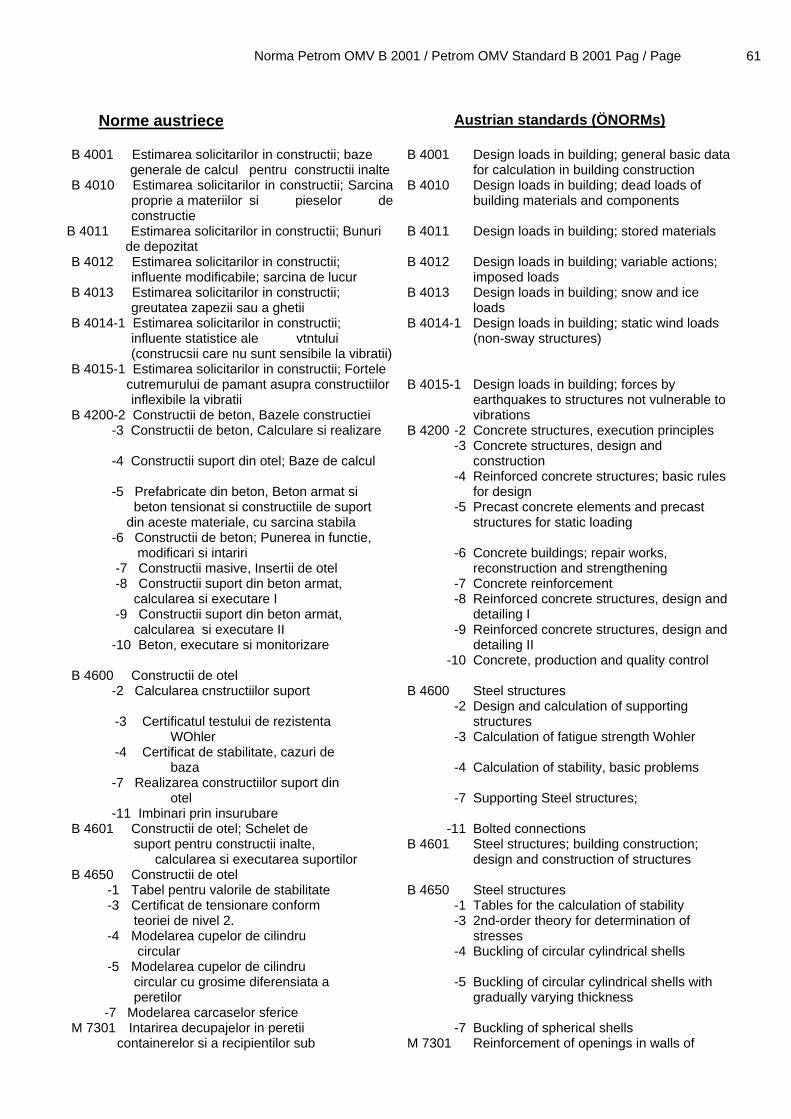
Norma Petrom OMV B 2001 / Petrom OMV Standard B 2001 Pag / Page 61
Norme austriece
Austrian standards (ÖNORMs)
B 4001 Estimarea solicitarilor in constructii; baze generale de calcul pentru constructii inalte B 4010 Estimarea solicitarilor in constructii; Sarcina
proprie a materiilor si pieselor de constructie
B 4011 Estimarea solicitarilor in constructii; Bunuri de depozitat
B 4012 Estimarea solicitarilor in constructii; influente modificabile; sarcina de lucur
B 4013 Estimarea solicitarilor in constructii; greutatea zapezii sau a ghetii
B 4014-1 Estimarea solicitarilor in constructii; influente statistice ale vtntului (construcsii care nu sunt sensibile la vibratii)
B 4015-1 Estimarea solicitarilor in constructii; Fortele cutremurului de pamant asupra constructiilor
inflexibile la vibratii B 4200-2 Constructii de beton, Bazele constructiei -3 Constructii de beton, Calculare si realizare -4 Constructii suport din otel; Baze de calcul -5 Prefabricate din beton, Beton armat si beton tensionat si constructiile de suport din aceste materiale, cu sarcina stabila -6 Constructii de beton; Punerea in functie, modificari si intariri -7 Constructii masive, Insertii de otel -8 Constructii suport din beton armat, calcularea si executare I -9 Constructii suport din beton armat, calcularea si executare II -10 Beton, executare si monitorizare B 4600 Constructii de otel -2 Calcularea cnstructiilor suport -3 Certificatul testului de rezistenta WOhler -4 Certificat de stabilitate, cazuri de baza -7 Realizarea constructiilor suport din otel -11 Imbinari prin insurubare B 4601 Constructii de otel; Schelet de suport pentru constructii inalte,
calcularea si executarea suportilor B 4650 Constructii de otel -1 Tabel pentru valorile de stabilitate -3 Certificat de tensionare conform teoriei de nivel 2. -4 Modelarea cupelor de cilindru circular -5 Modelarea cupelor de cilindru circular cu grosime diferensiata a peretilor -7 Modelarea carcaselor sferice M 7301 Intarirea decupajelor in peretii
containerelor si a recipientilor sub
B 4001 Design loads in building; general basic data for calculation in building construction
B 4010 Design loads in building; dead loads of building materials and components
B 4011 Design loads in building; stored materials B 4012 Design loads in building; variable actions;
imposed loads B 4013 Design loads in building; snow and ice
loads B 4014-1 Design loads in building; static wind loads
(non-sway structures) B 4015-1 Design loads in building; forces by
earthquakes to structures not vulnerable to vibrations
B 4200 -2 Concrete structures, execution principles -3 Concrete structures, design and
construction -4 Reinforced concrete structures; basic rules
for design -5 Precast concrete elements and precast
structures for static loading -6 Concrete buildings; repair works,
reconstruction and strengthening -7 Concrete reinforcement -8 Reinforced concrete structures, design and
detailing I -9 Reinforced concrete structures, design and
detailing II -10 Concrete, production and quality control B 4600 Steel structures -2 Design and calculation of supporting
structures -3 Calculation of fatigue strength Wohler -4 Calculation of stability, basic problems -7 Supporting Steel structures; -11 Bolted connections B 4601 Steel structures; building construction;
design and construction of structures B 4650 Steel structures -1 Tables for the calculation of stability -3 2nd-order theory for determination of
stresses -4 Buckling of circular cylindrical shells -5 Buckling of circular cylindrical shells with
gradually varying thickness -7 Buckling of spherical shells M 7301 Reinforcement of openings in walls of
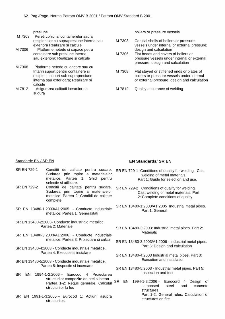
Pag /Page Norma Petrom OMV B 2001 / Petrom OMV Standard B 2001 62
presiune M 7303 Pereti conici ai containerelor sau a
recipientilor cu suprapresiune interna sau exteriora Realizare si calcule M 7306 Platforme netede si capace petru containere sub presiune interna sau exteriora; Realizare si calcule M 7308 Platforme netede cu ancore sau cu Intariri suport pentru containere si recipienti suport sub suprapresiune interna sau exterioara; Realizare si calcule M 7812 Asigurarea calitatii lucrarilor de sudura
boilers or pressure vessels M 7303 Conical shells of boilers or pressure
vessels under internal or external pressure; design and calculation
M 7306 Flat heads and covers of boilers or pressure vessels under internal or external pressure; design and calculation
M 7308 Flat stayed or stiffened ends or plates of
boilers or pressure vessels under internal or external pressure; design and calculation
M 7812 Quality assurance of welding
Standarde EN / SR EN SR EN 729-1 Conditii de calitate pentru sudare.
Sudarea prin topire a materialelor metalice. Partea 1: Ghid pentru selectie si utilizare.
SR EN 729-2 Conditii de calitate pentru sudare. Sudarea prin topire a materialelor metalice. Partea 2: Conditii de calitate complete.
SR EN 13480-1:2003/A1:2005 - Conducte industriale
metalice. Partea 1: Generalitati SR EN 13480-2:2003- Conducte industriale metalice. Partea 2: Materiale SR EN 13480-3:2003/A1:2006 - Conducte industriale
metalice. Partea 3: Proiectare si calcul SR EN 13480-4:2003 - Conducte industriale metalice. Partea 4: Executie si instalare SR EN 13480-5:2003 - Conducte industriale metalice. Partea 5: Inspectie si incercare SR EN 1994-1-2:2006 – Eurocod 4 Proiectarea
structurilor compozite de otel si beton Partea 1-2: Reguli generale. Calculul structurilor la foc
SR EN 1991-1-3:2005 – Eurocod 1: Actiuni asupra
structurilor.
EN Standards/ SR EN
SR EN 729-1 Conditions of quality for welding. Cast welding of metal materials.
Part 1: Guide for selection and use. SR EN 729-2 Conditions of quality for welding. Cast welding of metal materials. Part 2: Complete conditions of quality. SR EN 13480-1:2003/A1:2005 Industrial metal pipes.
Part 1: General SR EN 13480-2:2003: Industrial metal pipes. Part 2:
Materials SR EN 13480-3:2003/A1:2006 - Industrial metal pipes.
Part 3: Design and calculation SR EN 13480-4:2003 Industrial metal pipes. Part 3:
Execution and installation SR EN 13480-5:2003 - Industrial metal pipes. Part 5:
Inspection and test
SR EN 1994-1-2:2006 – Eurocord 4 Design of composed steel and concrete structures Part 1-2: General rules. Calculation of structures on fire
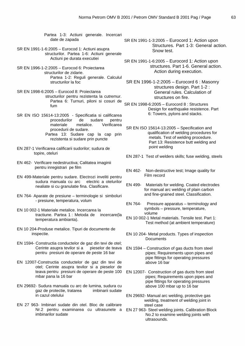
Norma Petrom OMV B 2001 / Petrom OMV Standard B 2001 Pag / Page 63
Partea 1-3: Actiuni generale. Incercari date de zapada
SR EN 1991-1-6:2005 – Eurocod 1: Actiuni asupra structurilor. Partea 1-6: Actiuni generale
Actiuni pe durata executiei SR EN 1996-1-2:2005 – Eurocod 6: Proiectarea structurilor de zidarie.
Partea 1-2: Reguli generale. Calculul structurilor la foc
SR EN 1998-6:2005 – Eurocod 8: Proiectarea structurilor pentru rezistenta la cutremur.
Partea 6: Turnuri, piloni si cosuri de fum
SR EN ISO 15614-13:2005 - Specificatia si calificarea
procedurilor de sudare pentru materiale metalice. Verificarea procedurii de sudare.
Partea 13: Sudare cap la cap prin rezistenta si sudare prin puncte
EN 287-1 Verificarea calificarii sudorilor; sudura de topire, oteluri EN 462- Verificare nedestructiva; Calitatea imaginii
pentru inregistrari pe film EN 499-Materiale pentru sudare. Electrozi inveliti pentru
sudura manuala cu arc electric a otelurilor nealiate si cu granulatie fina. Clasificare.
EN 764- Aparate de presiune – terminologie si simboluri
- presiune, temperatura, volum EN 10 002-1 Materiale metalice. Incercarea la
tractiune. Partea 1 : Metoda de incercare(la temperatura ambianta).
EN 10 204-Produse metalice. Tipuri de documente de inspectie. EN 1594- Constructia conductelor de gaz din tevi de otel;
Cerinte asupra tevilor si a pieselor de teava pentru presiuni de operare de peste 16 bar
EN 12007-Constructia conductelor de gaz din tevi de
otel; Cerinte asupra tevilor si a pieselor de teava pentru presiuni de operare de peste 100 mbar pana la 16 bar
EN 29692- Sudura manuala cu arc de lumina, sudura cu
gaz de protectie, tratarea imbinarii sudate in cazul otelului
EN 27 963- Imbinari sudate din otel. Bloc de calibrare
Nr.2 pentru examinarea cu ultrasunete a imbinarilor sudate
SR EN 1991-1-3:2005 – Eurocord 1: Action upon
Structures. Part 1-3: General action. Snow test.
SR EN 1991-1-6:2005 – Eurocord 1: Action upon structures. Part 1-6. General action.
Action during execution. SR EN 1996-1-2:2005 – Eurocord 6 : Masonry
structures design. Part 1-2 : General rules. Calculation of structures on fire.
SR EN 1998-6:2005 – Eurocord 8 : Structures Design for earthquake resistence. Part 6: Towers, pylons and stacks. SR EN ISO 15614-13:2005 – Specification and qualification of welding procedures for metals. Test of welding procedure. Part 13: Resistence butt welding and point welding EN 287-1 Test of welders skills; fuse welding, steels EN 462- Non-destructive test; Image quality for Film record EN 499- Materials for welding. Coated electrodes for manual arc welding of plain carbon and fine-grained steel. Classification. EN 764- Pressure apparatus – terminology and symbols – pressure, temperature, volume EN 10 002-1 Metal materials. Tensile test. Part 1: Test method (at ambient temperature) EN 10 204- Metal products. Types of inspection Documents EN 1594 – Construction of gas ducts from steel pipes; Requirements upon pipes and pipe fittings for operating pressures above 16 bar EN 12007- Construction of gas ducts from steel pipes; Requirements upon pipes and pipe fittings for operating pressures above 100 mbar up to 16 bar EN 29692- Manual arc welding, protective gas welding, treatment of welding joint in steel case EN 27 963- Steel welding joints. Calibration Block No.2 to examine welding joints with ultrasounds.
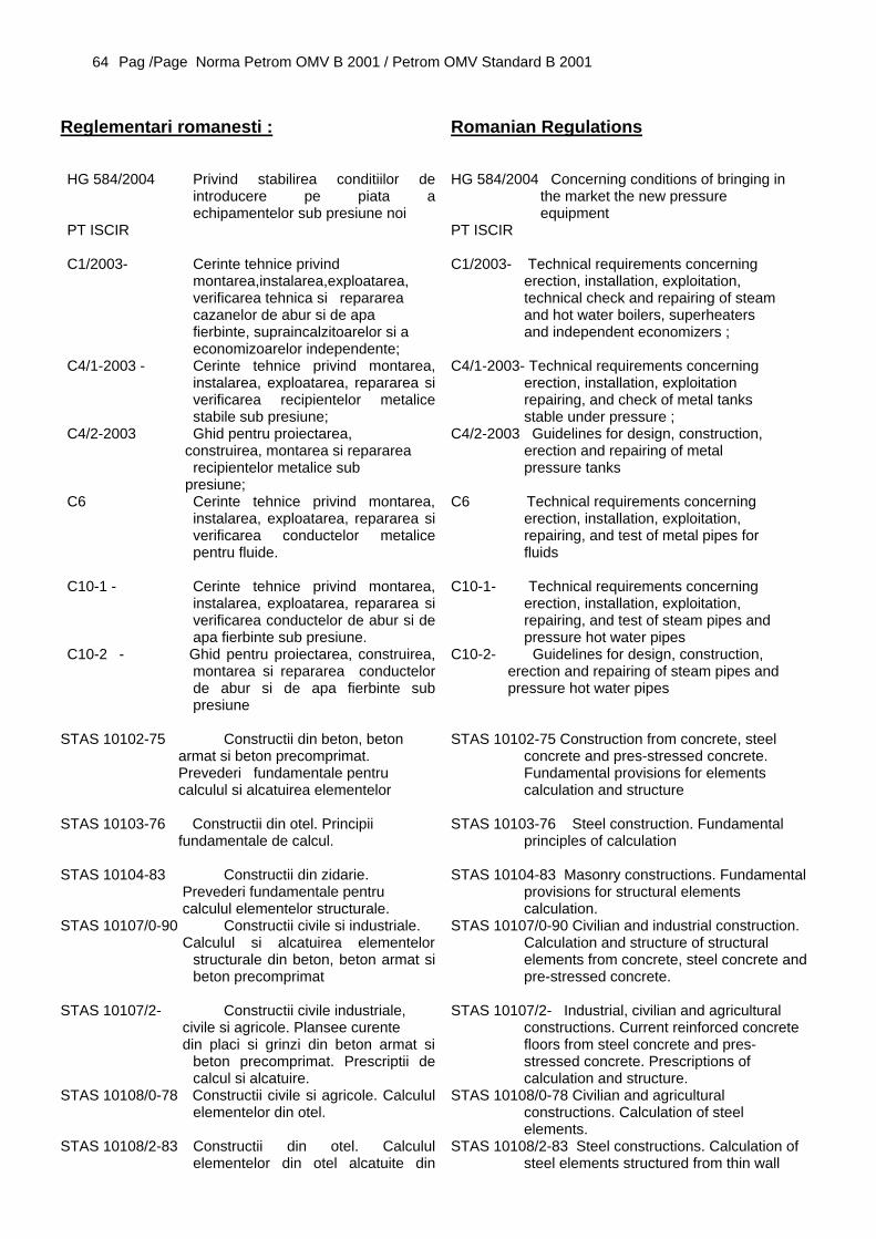
Pag /Page Norma Petrom OMV B 2001 / Petrom OMV Standard B 2001 64
Reglementari romanesti :
Romanian Regulations
HG 584/2004 Privind stabilirea conditiilor de
introducere pe piata a echipamentelor sub presiune noi
PT ISCIR C1/2003- Cerinte tehnice privind
montarea,instalarea,exploatarea, verificarea tehnica si repararea cazanelor de abur si de apa fierbinte, supraincalzitoarelor si a economizoarelor independente;
C4/1-2003 - Cerinte tehnice privind montarea, instalarea, exploatarea, repararea si verificarea recipientelor metalice stabile sub presiune;
C4/2-2003 Ghid pentru proiectarea, construirea, montarea si repararea recipientelor metalice sub presiune; C6 Cerinte tehnice privind montarea,
instalarea, exploatarea, repararea si verificarea conductelor metalice pentru fluide.
C10-1 - Cerinte tehnice privind montarea,
instalarea, exploatarea, repararea si verificarea conductelor de abur si de apa fierbinte sub presiune.
C10-2 - Ghid pentru proiectarea, construirea, montarea si repararea conductelor de abur si de apa fierbinte sub presiune
STAS 10102-75 Constructii din beton, beton armat si beton precomprimat. Prevederi fundamentale pentru calculul si alcatuirea elementelor STAS 10103-76 Constructii din otel. Principii fundamentale de calcul. STAS 10104-83 Constructii din zidarie. Prevederi fundamentale pentru calculul elementelor structurale. STAS 10107/0-90 Constructii civile si industriale. Calculul si alcatuirea elementelor
structurale din beton, beton armat si beton precomprimat
STAS 10107/2- Constructii civile industriale, civile si agricole. Plansee curente din placi si grinzi din beton armat si
beton precomprimat. Prescriptii de calcul si alcatuire.
STAS 10108/0-78 Constructii civile si agricole. Calculul elementelor din otel.
STAS 10108/2-83 Constructii din otel. Calculul
elementelor din otel alcatuite din
HG 584/2004 Concerning conditions of bringing in the market the new pressure equipment PT ISCIR
C1/2003- Technical requirements concerning erection, installation, exploitation, technical check and repairing of steam and hot water boilers, superheaters and independent economizers ; C4/1-2003- Technical requirements concerning erection, installation, exploitation repairing, and check of metal tanks stable under pressure ; C4/2-2003 Guidelines for design, construction, erection and repairing of metal pressure tanks C6 Technical requirements concerning erection, installation, exploitation, repairing, and test of metal pipes for fluids C10-1- Technical requirements concerning erection, installation, exploitation, repairing, and test of steam pipes and pressure hot water pipes C10-2- Guidelines for design, construction, erection and repairing of steam pipes and pressure hot water pipes STAS 10102-75 Construction from concrete, steel
concrete and pres-stressed concrete. Fundamental provisions for elements calculation and structure
STAS 10103-76 Steel construction. Fundamental
principles of calculation STAS 10104-83 Masonry constructions. Fundamental
provisions for structural elements calculation.
STAS 10107/0-90 Civilian and industrial construction. Calculation and structure of structural elements from concrete, steel concrete and pre-stressed concrete.
STAS 10107/2- Industrial, civilian and agricultural
constructions. Current reinforced concrete floors from steel concrete and pres-stressed concrete. Prescriptions of calculation and structure.
STAS 10108/0-78 Civilian and agricultural constructions. Calculation of steel elements.
STAS 10108/2-83 Steel constructions. Calculation of steel elements structured from thin wall
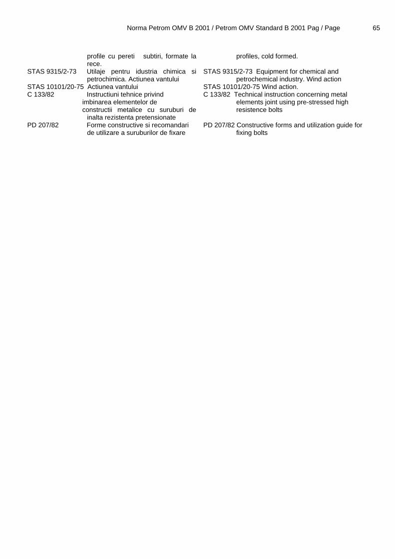
Norma Petrom OMV B 2001 / Petrom OMV Standard B 2001 Pag / Page 65
profile cu pereti subtiri, formate la rece.
STAS 9315/2-73 Utilaje pentru idustria chimica si petrochimica. Actiunea vantului
STAS 10101/20-75 Actiunea vantului C 133/82 Instructiuni tehnice privind imbinarea elementelor de constructii metalice cu suruburi de
inalta rezistenta pretensionate PD 207/82 Forme constructive si recomandari
de utilizare a suruburilor de fixare
profiles, cold formed. STAS 9315/2-73 Equipment for chemical and
petrochemical industry. Wind action STAS 10101/20-75 Wind action. C 133/82 Technical instruction concerning metal
elements joint using pre-stressed high resistence bolts
PD 207/82 Constructive forms and utilization guide for
fixing bolts

Pag /Page Norma Petrom OMV B 2001 / Petrom OMV Standard B 2001 66
DIN DIN1942 Verificarile de aprobare a generatoarelor de aburi, tevi de otel -1 calcularea grosimii peretilor pentru tevi de otel ptr. presiune interna -2 calcularea arcurilor de teava pentru
presiune interioara 2505 Calcularea imbinarilor cu flanse 2559 Pregatirea imbinarilor sudate -1 Directive pentru forma rosturilor, sudura de topire a tevilor de otel -2 Adaptarea diametrului interior la sudurile circulare pe tevi neintrerupte 2922 Trapa de explozie 45 x 45 4755 -1 Sisteme de ardere a combustibil lichid; Arderea combustibil lichid in instalatii de incalzire; cerinte tehnice de siguranta 4755 Sisteme de ardere a combustibil lichid – reguli tehncie pentru instalatia de arderea a combustibil lichid (TRO) – cerinte tehnice de siguranta, verificare (schita normei 2/2001)
4756 Sisteme de ardere a gazului; arderea gazului in instalatii de incalzire; cerinte tehnice de siguranta 4787 -1 Arzatoare de combustibil lichid
pulverizat; termeni, cerinte tehnice de siguranta; verificare, marcare 4788 -1 Arzatoare de gaz; arzatoare de gaz fara suflanta 17 175 Tevi neintrerupte din otel rezistent termic; cerinte tehnice de livrare 28 070 Cuptoare chimice cu izolatie; principii de baza pentru constructia cuptoarelor 28 071 Cuptoare chimice cu izolatie; principii de baza pentru izolatie 45 635 Masurarea zgomotului instalatiilor 50 104 Test de presiune interioara pe corpuri goale; verificarea etanseiitatii pana la o anumita presiune interioara; specificatie generala 50 115 Verificarea materiilor prime metalice; teste de lovire si zgariere; forme specifice de verificare si procedee de evaluare 50 150 Verificarea materiilor prime metalice – convertirea valorilor de duritate 50 914 Verificarea otelurilor inoxidabile pentru rezistenta la corosiune intercristalina 54111 Verificare nedestructiva; Verificarea materiilor metalice cu raze Rontgen si raze Gamma 54120 Verificare nedestructiva a materiilor prime; corp de control 1 si utilizarea sa pentru ajustarea si controlul aparatelor de
ultrasunet, impuls - ecou.
55928 Protectia anticorosiva a constructiilor de otel prin straturi de protectie si invelisuri
1942 Thermal acceptance tests of steam turbines, steel pipes
-1 Calculation of the wall thickness of steel tubes against internal pressure
-2 Calculation of elbows of steel tubes against internal pressure
2505 Calculation of flange connections 2559 Edge preparation for welding -1 Types of groove, fusion welding of butt joints in
steel tubes -2 Matching of inside diameter for circumferential
welds on seamless pipes 2922 Explosion openings 45 x 45 4755 -1 Oil firing installations; oil firing in heating
installations; technical safety requirements 4755 Oil firing installations - Technical regulations
for oil firing installation (TRÖ) - Technical Safety Requirements, Testing (Standard draft 2/2001)
4756 Gas firing installations; gas firing in heating
installations; technical safety requirements 4787 -1 Atomizing oil burners; Concepts, safety
requirements, testing marking 4788 -1 Gas burners; Gas burners without blowers 17 175 Seamless tubes of heat-resistant steels;
technical conditions of delivery 28 070 Furnaces with lining for the chemical industry;
instructions for design 28 071 Furnaces with lining for the chemical industry;
instructions for brick-lining 45 635 Measurement of noise emitted by machines 50 104 Testing of hollow bodies by internal pressure;
leak detection up to a certain pressure value; general specifications
50 115 Notched bar impact testing of metallic
materials using test pieces other than ISO test pieces; Test of metal raw materials; scratches and impact tests; specific tests and evaluation procedures
50 150 Testing of metallic materials - Hardness
conversion tables 50 914 Testing the resistance of stainless steels to
intercrystalline corrosion 54111 Nondestructive testing; testing of metallic
materials by X- and gamma rays 54120 Nondestructive testing; Calibration block 1 and
its use for the adjustment and control of ultrasonic echo equipment
55928 Protection of steel structures against corrosion
by organic and metallic coatings
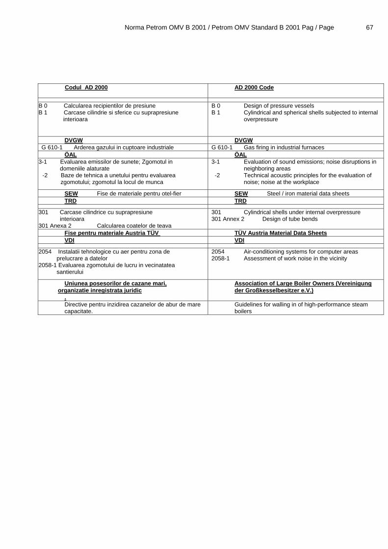
Norma Petrom OMV B 2001 / Petrom OMV Standard B 2001 Pag / Page 67
Codul AD 2000
AD 2000 Code
B 0 Calcularea recipientilor de presiune B 1 Carcase cilindrie si sferice cu suprapresiune interioara
B 0 Design of pressure vessels B 1 Cylindrical and spherical shells subjected to internal
overpressure
DVGW DVGWG 610-1 Arderea gazului in cuptoare industriale G 610-1 Gas firing in industrial furnaces
ÖAL ÖAL3-1 Evaluarea emissilor de sunete; Zgomotul in domeniile alaturate
-2 Baze de tehnica a unetului pentru evaluarea zgomotului; zgomotul la locul de munca
3-1 Evaluation of sound emissions; noise disruptions in neighboring areas
-2 Technical acoustic principles for the evaluation of noise; noise at the workplace
SEW Fise de materiale pentru otel-fier SEW Steel / iron material data sheets TRD TRD
301 Carcase cilindrice cu suprapresiune interioara 301 Anexa 2 Calcularea coatelor de teava
301 Cylindrical shells under internal overpressure 301 Annex 2 Design of tube bends
Fise pentru materiale Austria TÜV TÜV Austria Material Data SheetsVDI VDI
2054 Instalatii tehnologice cu aer pentru zona de prelucrare a datelor 2058-1 Evaluarea zgomotului de lucru in vecinatatea santierului
2054 Air-conditioning systems for computer areas 2058-1 Assessment of work noise in the vicinity
Uniunea posesorilor de cazane mari, organizatie inregistrata juridic
.
Association of Large Boiler Owners (Vereinigung der Großkesselbesitzer e.V.)
Directive pentru inzidirea cazanelor de abur de mare capacitate.
Guidelines for walling in of high-performance steam boilers

Pag /Page Norma Petrom OMV B 2001 / Petrom OMV Standard B 2001 68
Anexa 2 - Tipuri constructive de cuptoare
19.0 Annex 2 - Furnace designs
Figua 1 Figura 2 Figura 3 Fi 3
Figures 2 Figures 3 Figures 1
Figura 4 Figura 5 Figura 6 Fi 6
Figures 4 Figures 5 Figures 6

Norma Petrom OMV B 2001 / Petrom OMV Standard B 2001 Pag / Page 69
Figura 7 Figura 8 Figura 9
Figures 9 Figures 7 Figures 8
Figura 11 0
Figura 1Figures 11 Figures 10
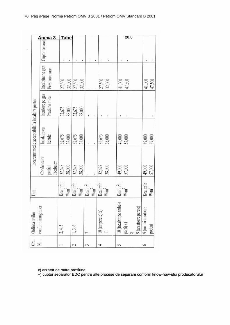
Pag /Page Norma Petrom OMV B 2001 / Petrom OMV Standard B 2001 70
Anexa 3 – Tabel 20.0
x) arzator de mare presiune x) arzator de mare presiune +) cuptor separator EDC pentru alte procese de separare conform know-how-ului producatorului +) cuptor separator EDC pentru alte procese de separare conform know-how-ului producatorului

Norma Petrom OMV B 2001 / Petrom OMV Standard B 2001 Pag / Page 71

Pag /Page Norma Petrom OMV B 2001 / Petrom OMV Standard B 2001 72
REVIZUIT REVISIONS
0/May 2006 Preluarea si adaptarea normei OMV B 2001/1.05.2001 1/Dec.2006 Schimbare format
0/May 2006 Processing and adapting of OMV Norm B 2001/1.05.2001 1/Dec.2006 Format change