asee 2011 mihaela paper
TRANSCRIPT

8/20/2019 ASEE 2011 Mihaela Paper
http://slidepdf.com/reader/full/asee-2011-mihaela-paper 1/12
AC 2011-1104: USE OF ELECTRONICS EXPLORER BOARD
Mihaela Radu, Rose-Hulman Institute of Technology
Dr. Mihaela Radu received the M. Eng. degree in Electronics and Telecommunications Engineering
from the Polytechnic Institute of Cluj-Napoca, Romania, in 1985, and a Ph.D. in Electrical Engineering
from the Technical University of Cluj-Napoca, in 2000. Since 1991 she has been an Assistant Profes-
sor, then Associate Professor with The Technical University of Cluj-Napoca, Faculty of Electronics and
Telecommunications. In 2003 she joined Rose-Hulman Institute of Technology, Terre Haute, Indiana, as
Associate Professor, Over the past ten years she taught several courses on Electronic Components and
Circuits, Digital Systems, Design of Fault Tolerant Systems and Testing of Digital Systems. Her current
research interests include Fault Tolerance of Electronic Systems, Programmable Logic Devices and new
educational methods to teach digital system design and analog electronics.
Clint S Cole, Digilent, Inc.
Clint graduated from Washington State University in 1987 with a BS degree in computer science, and
worked for Hewlett-Packard and Physio-Control before co-founding Heartstream in 1991. Heartstream
pioneered the design of ultra-portable, low-cost defibrillators that are now deployed in millions of settings
around the world. After Hewlett-Packard purchased Heartstream in 1997, Clint returned to WSU to
complete a MSEE degree in 1999, and soon after co-founded Digilent. Digilent was formed to createproducts and services to help educate electrical engineers, and has since grown to become the world’s
leading supplier of programmable logic design kits, with products used by more than 80,000 students per
semester in more than 1000 Universities worldwide.
Joe Harris, Digilent, Inc.
Joe Harris, MBA, JD, Director of Business Development, manages overseas offices, development of Dig-
ilent’s education product line, and corporate issues. Mr. Harris has worked in the high-tech industry for
several years and is a Fulbright Fellow to Albania where he worked with micro-business development
issues.
Mircea Dabacan, Technical University of Cluj-Napoca
Professor at the Technical University of Cluj-Napoca, Romania, Faculty for Electronics, Telecommunica-
tions and Information Technology, Applied Electronics Department. General Manager of Digilent RO
cAmerican Society for Engineering Education, 2011

8/20/2019 ASEE 2011 Mihaela Paper
http://slidepdf.com/reader/full/asee-2011-mihaela-paper 2/12
Use of Electronics Explorer Board
in Electrical Engineering Education
Abstract
According to a report published for The Royal Academy of Engineering, UK (2006), the pace ofchange in industry is expected to intensify in both the technological and non-technologicaldomains. Certain disciplines, including electrical/electronic and system engineering are seen as particular likely to be of increasing importance over the next ten years. The same report claimsthat certain topics are seen by students to be more difficult than others which can lead to skills’shortage in some particular areas. Noting for example that analog electronics is often perceivedas a harder subject than digital electronics, students are inclined to decide on the latter, leading toa shortage of skilled engineers in analog electronic design.
At the level of digital circuits, the “more you push the technology, the more analog it becomes”,therefore more integrated circuit designers, both analog and digital, need to have a familiarity
and comfort level with analog circuits.
Additionally, in today’s world, the tools, technologies, and methods used by engineers inelectrical engineering design evolve quickly and continuously. Educational programs must keep pace with these changing tools, technologies, and methods in order to produce graduates whomeet the needs of employers and are competitive in the marketplace. To meet this need,engineering education programs must target their laboratory experiences to take advantage of thenewest technologies and expose students to the tools and methods employed by practicingengineers, while emphasizing fundamental concepts and principles.
A new approach, in which every student has their own integrated analog circuit design station,
holds the promise to significantly improve educational outcomes in this area. A new productcalled the “Electronic Explorer Board” has recently come to market that provides everythingstudents need to design, build, and test analog circuits in a single, low-cost, and portable station.This paper presents a study of the effectiveness of providing students with unlimited access toElectronic Explorer Boards, beyond the traditional laboratory settings. The study conducted atRose Hulman Institute of Technology tries to determine if the use of Electronic Explorer boardshelps to improve the learning process, development of problem solving skills, the attainment ofspecific knowledge and skills, and the proper use of instrumentation tools.
Introduction
According to a report published for The Royal Academy of Engineering, UK (2006) 1, the pace
of change in industry is expected to intensify in both the technological and non-technologicaldomains. Certain disciplines, including electrical/electronic and system engineering are seen as particular likely to be of increasing importance over the next ten years. Looking at particularskills and attributes needed for engineers, there is strong evidence that the top priorities in termsof future skills will be: (a) practical applications, (b) theoretical understanding and (c) creativityand innovation.

8/20/2019 ASEE 2011 Mihaela Paper
http://slidepdf.com/reader/full/asee-2011-mihaela-paper 3/12
The same report claims that certain topics are seen by students to be more difficult than otherswhich can lead to skills’ shortage in some particular areas. Noting for example that analogelectronics is often perceived as a harder subject than digital electronics, students are inclined todecide on the latter, leading to a shortage of skilled engineers in analog electronic design 1.
At the level of digital circuits, the “more you push the technology, the more analog it becomes”.Therefore the well rounded integrated circuit designer, in both analog and digital circuits, needsto have a familiarity and comfort level with analog circuits. However, the lack of conceptualframework for the understanding of analog circuit behavior has left many electrical andcomputer engineering students believing that analog circuit design is an impossible topic tomaster. The current method of teaching analog circuits focuses on procedural, quantitative andanalytical methods to describe individual circuits
2.
According to3, there are four types of learners: Type 1(concrete, reflective)-the diverger; Type2(abstract, reflective)-the assimilator; Type 3(abstract, active)-the converger; Type 4 (concrete, active)-the accommodator. Traditional science and engineering instruction focuses almost
exclusively on lecturing, a style comfortable for only Type 2 learners. Effective instructioninvolves teaching all learning styles–motivating each new topic (Type 1), presenting the basicinformation and methods associated with the topic (Type 2), providing opportunities for practicing the methods (Type 3), and encouraging exploration of applications (Type 4). By providing students with more opportunities for hands-on experience, encouraging exploration ofapplications and providing more time for practicing the techniques and concepts taught intheoretical lectures, a more effective instruction can be provided, addressing all four types oflearners.
Additionally, in today’s world, the tools, technologies, and methods used by engineers inelectrical engineering design evolve quickly and continuously. Educational programs must keep pace with these changing tools, technologies, and methods in order to produce graduates whomeet the needs of employers and are competitive in the marketplace. To meet this need,engineering education programs must target their laboratory experiences to take advantage of thenewest technologies and expose students to the tools and methods employed by practicingengineers, while emphasizing fundamental concepts and principles.
Today, university-based educational programs invest heavily in many new tools andtechnologies, often only using them in more advanced or project-based courses. Faculty and staffcontribute large amounts of time preparing new course materials that students need to learn thesenew tools. Because new tools are often far too expensive and complex for use outside of thelaboratory, the vast majority of programs provide only limited access to these technologies in theform of two or three hour weekly lab sessions, constraining the amount of time students can usethe tools. During these sessions, students must apply concepts learned in lectures, use complexlaboratory equipment to build experiments, develop hardware debugging skills.
According to4, there are 13 fundamental objectives of Engineering Instructional Laboratories,
that students should understand or acquire skills in: (1) Instrumentation; (2) Models; (3) Experiment; (4) Data Analysis; (5) Design; (6) Learning from Failure; (7) Creativity; (8)Psychomotor; (9) Safety; (10) Communication; (11) Team work; (12) Ethics in the Laboratory;

8/20/2019 ASEE 2011 Mihaela Paper
http://slidepdf.com/reader/full/asee-2011-mihaela-paper 4/12
(13) Sensory Awareness. In the current laboratory setting and approach there are significant timeand resource constraints, and students have to master complex tools and technologies. As aresult, students tend not to achieve all their lab objectives, and consequently do not develop theskills required by the engineering industry.
A new approach, in which every student has their own integrated analog circuit design station,holds the promise to significantly improve educational outcomes in this area. A new productcalled the “Electronic Explorer Board”
5 has recently come to market that provides everything
students need to design, build, and test analog circuits in a single, low-cost, and portable station.
This paper presents a study of the effectiveness of providing students with unlimited access to anintegrated analog circuit design station (Electronic Explorer Board), beyond the traditionallaboratory settings. By allowing the students to have their own Electronic Explorer Boards withwhich they can work anytime and anywhere, students have more time to achieve the instructionallab objectives. In addition, by providing students with more opportunities for hands-onexperience, encouraging exploration of applications and providing more time for practicing the
techniques and concepts taught in theoretical lectures, a more effective instruction is provided,addressing all four types of learners, as described earlier. The study conducted at Rose HulmanInstitute of Technology (RHIT) tries to determine if the use of Electronic Explorer boards helpsto improve the learning process, development of problem solving skills, the attainment ofelectronics’ specific knowledge and skills, and the proper use of instrumentation tools .Quantitative data are analyzed by comparison to historical data gathered from student groups thatdid not have unlimited access to the Electronic Explorer board.
Presentation of Electronic Explorer Boards
The EE board is a complete, integrated analog circuit design workstation that students can use todesign, implement and test all types of analog circuits. It combines a solder less breadboard, programmable power supplies, and multiple test and measurement devices into a single devicethat is both low cost and highly portable. It uses a USB2 port and a PC running the freeWaveforms™ software for control and display to create a powerful design station. See figure 1.
Fig. 1 Electronic Explorer Board

8/20/2019 ASEE 2011 Mihaela Paper
http://slidepdf.com/reader/full/asee-2011-mihaela-paper 5/12
8/20/2019 ASEE 2011 Mihaela Paper
http://slidepdf.com/reader/full/asee-2011-mihaela-paper 6/12
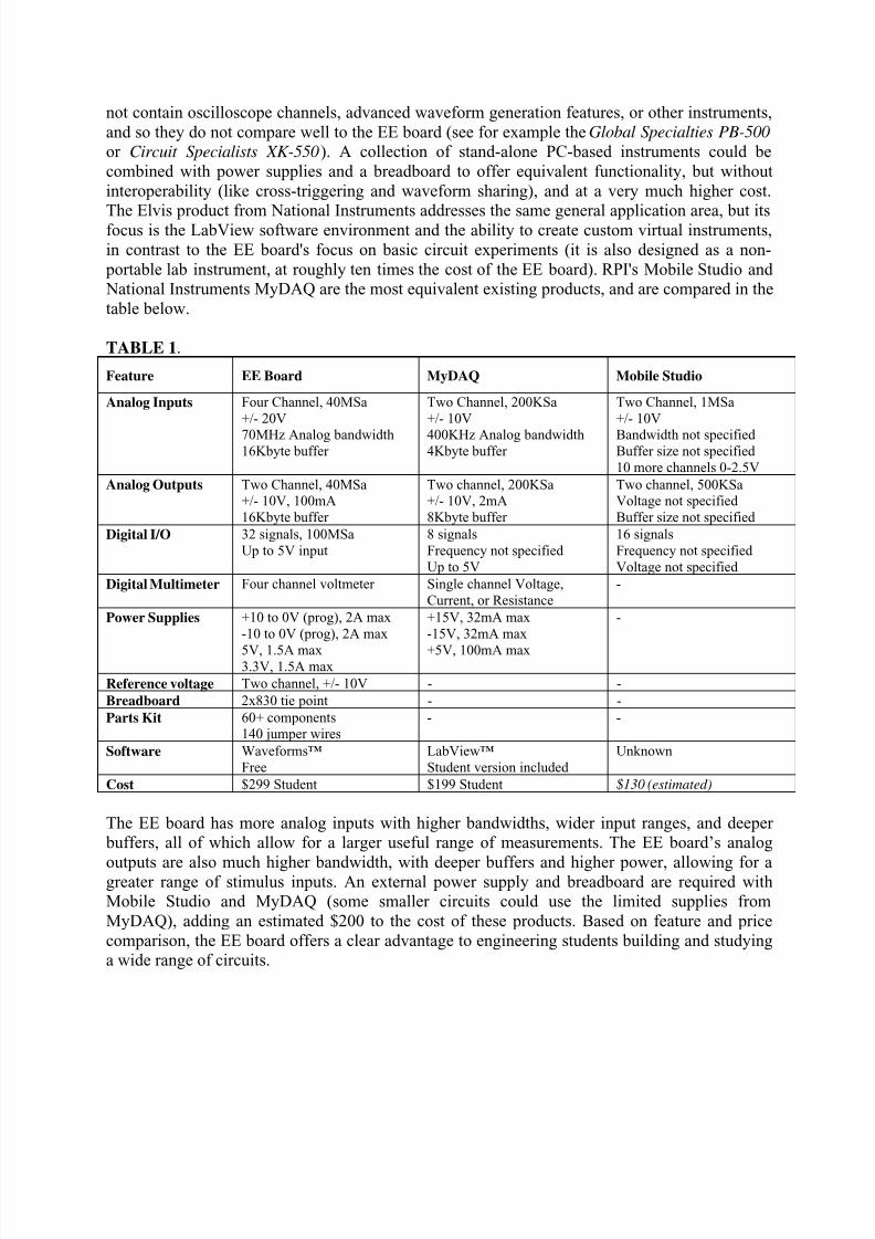
not contain oscilloscope channels, advanced waveform generation features, or other instruments,and so they do not compare well to the EE board (see for example the Global Specialties PB-500 or Circuit Specialists XK-550). A collection of stand-alone PC-based instruments could becombined with power supplies and a breadboard to offer equivalent functionality, but withoutinteroperability (like cross-triggering and waveform sharing), and at a very much higher cost.
The Elvis product from National Instruments addresses the same general application area, but itsfocus is the LabView software environment and the ability to create custom virtual instruments,in contrast to the EE board's focus on basic circuit experiments (it is also designed as a non- portable lab instrument, at roughly ten times the cost of the EE board). RPI's Mobile Studio and National Instruments MyDAQ are the most equivalent existing products, and are compared in thetable below.
TABLE 1.
Feature EE Board MyDAQ Mobile Studio
Analog Inputs Four Channel, 40MSa+/- 20V
70MHz Analog bandwidth16Kbyte buffer
Two Channel, 200KSa+/- 10V
400KHz Analog bandwidth4Kbyte buffer
Two Channel, 1MSa+/- 10V
Bandwidth not specifiedBuffer size not specified10 more channels 0-2.5V
Analog Outputs Two Channel, 40MSa+/- 10V, 100mA16Kbyte buffer
Two channel, 200KSa+/- 10V, 2mA8Kbyte buffer
Two channel, 500KSaVoltage not specifiedBuffer size not specified
Digital I/O 32 signals, 100MSaUp to 5V input
8 signalsFrequency not specifiedUp to 5V
16 signalsFrequency not specifiedVoltage not specified
Digital Multimeter Four channel voltmeter Single channel Voltage,Current, or Resistance
-
Power Supplies +10 to 0V (prog), 2A max-10 to 0V (prog), 2A max
5V, 1.5A max3.3V, 1.5A max
+15V, 32mA max-15V, 32mA max
+5V, 100mA max
-
Reference voltage Two channel, +/- 10V - -
Breadboard 2x830 tie point - -
Parts Kit 60+ components140 jumper wires
- -
Software Waveforms™Free
LabView™Student version included
Unknown
Cost $299 Student $199 Student $130 (estimated)
The EE board has more analog inputs with higher bandwidths, wider input ranges, and deeper buffers, all of which allow for a larger useful range of measurements. The EE board’s analog
outputs are also much higher bandwidth, with deeper buffers and higher power, allowing for agreater range of stimulus inputs. An external power supply and breadboard are required withMobile Studio and MyDAQ (some smaller circuits could use the limited supplies fromMyDAQ), adding an estimated $200 to the cost of these products. Based on feature and pricecomparison, the EE board offers a clear advantage to engineering students building and studyinga wide range of circuits.
8/20/2019 ASEE 2011 Mihaela Paper
http://slidepdf.com/reader/full/asee-2011-mihaela-paper 7/12
Short Description of the Courses Using the EE boards
At Rose Hulman Institute of Technology, in the academic year 2010-2011 fall quarter, in the course ECE 250- Electronic Device Modeling, students were given Electronic Explorer boards atthe beginning of the quarter, and they were allowed to keep them for the entire quarter. The useof the EE boards was optional this academic year.
The course ECE 250-Electronic Device Modeling is a sophomore level course, intended to provide students with the basic understanding of the nonlinear devices used in electronic circuits,such as diodes and transistors. Topics are covered in the following order: theoretical analysis,simulation and laboratory verification. Theoretical analysis of the circuit is covered tounderstand the operation of the circuit or to design a circuit. Circuit simulation using industrystandard analysis tools (OrCAD PSpice) is used to verify the theoretical analysis or circuitdesign. The circuits are constructed in the labs if the simulation agrees with the theoreticalanalysis. Measurements of the circuit performance are made and compared to the theoreticalcalculations and simulation results.
Important course objectives are: Characterize two and three terminal devices by means of I-V plots; Derive a linearized small-signal model given the large signal characteristics; Describe acircuit and analyze its operation in terms of the bias and small signal-model, or its large-signalswitching model; Use OrCAD PSpice or other computer simulation tool to model circuit behavior and discuss the difference between the DC, time-domain and frequency domainanalysis; Measure the DC characteristics of a 2 or 3 terminal device in the laboratory; Constructand test small rectifier and transistor circuits in the laboratory; Use elementary troubleshootingtechniques and critical error analysis in the laboratory; Use standard written and oral formats toreport laboratory/computation results; Demonstrate the similarity of operation between all 3terminals devices that can be used as amplifiers or switches; Show how these three terminalsdevices can be used as switches or amplifiers; Understand the properties of semiconductormaterials such as doping, carrier concentration, conductivity, drift and diffusion current.
Laboratory experiments cover circuits with rectifying and Zener diodes, circuits with bipolar junction transistors (BJTs) and field effect transistors (FETs) as amplifiers and switches.
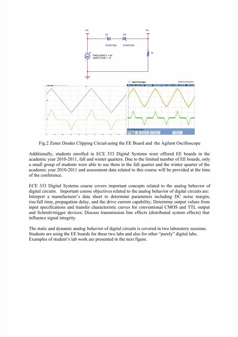
Students enrolled in the ECE 250 class were allowed to use the EE boards to build and test theircircuits at home, before coming to the lab sessions. Measurements using the instruments of theEE boards were compared with the measurements using traditional laboratory instruments(Agilent technology), especially for the most difficult portions of the laboratory experiments.Students’ presence in the lab was requested in order to answer instructor’s questions, to check iftheir laboratory experiments and the interpretation of their results were correct and to prepare professional laboratory reports. Instructor had more time to spend with students with weak backgrounds, helping them with the debugging skills and the interpretation of theirmeasurements, especially for more advanced laboratory experiments such as: switching time ofdiodes, one stage amplifiers with BJT and FET transistors. Examples of student’s lab workusing the EE board and Agilent Oscilloscope are presented in the next figure.
8/20/2019 ASEE 2011 Mihaela Paper
http://slidepdf.com/reader/full/asee-2011-mihaela-paper 8/12
Vin Vo
-
+ V1
FREQUENCY = 60
AMPLITUDE = 10
D1
D1N4733A
D2
D1N4733A
+
1k
Fig.2 Zener Diodes Clipping Circuit using the EE Board and the Agilent Oscilloscope
Additionally, students enrolled in ECE 333 Digital Systems were offered EE boards in theacademic year 2010-2011, fall and winter quarters. Due to the limited number of EE boards, onlya small group of students were able to use them in the fall quarter and the winter quarter of theacademic year 2010-2011 and assessment data related to this course will be provided at the time
of the conference.
ECE 333 Digital Systems course covers important concepts related to the analog behavior ofdigital circuits. Important course objectives related to the analog behavior of digital circuits are:Interpret a manufacturer’s data sheet to determine parameters including DC noise margin,rise/fall time, propagation delay, and the drive current capability; Determine output values frominput specifications and transfer characteristic curves for conventional CMOS and TTL outputand Schmitt-trigger devices; Discuss transmission line effects (distributed system effects) thatinfluence signal integrity.
The static and dynamic analog behavior of digital circuits is covered in two laboratory sessions.
Students are using the EE boards for these two labs and also for other “purely” digital labs.Examples of student’s lab work are presented in the next figure.

8/20/2019 ASEE 2011 Mihaela Paper
http://slidepdf.com/reader/full/asee-2011-mihaela-paper 9/12
Fig.3 The Transfer Characteristics of TTL (a) and CMOS (b) Inverter using the EE Board (a)and the Agilent Oscilloscope (b)
Both courses are taught in a 10 week quarter with 3 lectures per week and a single 3 hour lab perweek. More details about the courses can be found at
6.
ASSESSMENT DATA
At Rose Hulman Institute of Technology the study is conducted by the course instructor. Thecourse ECE 250-Electronic Device Modeling was taught by the same instructor, using the samesyllabus and textbook 7 in the last two academic years, fall quarter. At RHIT, due to the smallstudent population and the small class size, a blind study was not possible. Various assessmenttechniques are used trying to gain support for the study. The study will continue in the next twoacademic years.
The impact of unlimited access to EE boards on the students’ educational experience is
investigated by looking at how students’ learning was improved. Evaluation of students’ learningwas gained through course exam grades, practical labs grades and concept inventory results.Additionally, end of quarter course’s evaluations were investigated to evaluate students’ perception about their learning.
In the academic year 2009-2010, 25 students were enrolled in the Electronic Device Modelingcourse. Traditional laboratory equipment (Agilent technology) was used for the laboratoryexperiments during the 3 hours of lab sessions. In the next academic year, 10 students wereenrolled in the Electronic Device Modeling course and they were given EE boards. Five studentsdecided to use the EE boards on regular basis for the laboratory experiments and to explore othercircuits on their own, at home.
-The exam grades and the final grades show an increase from the academic year 2009- 2010 tothe next academic year. The first exam covers circuits with diodes, the second exam covers bipolar junction transistors and the third one covers circuits with field effect transistors andcalculations of input/output impedance of single stage amplifiers. All exams include conceptual(theoretical) questions and three problems, some of them similar to laboratory experiments. Theexams had the same degree of difficulty in both academic years.

8/20/2019 ASEE 2011 Mihaela Paper
http://slidepdf.com/reader/full/asee-2011-mihaela-paper 10/12
The final grade for this class includes exam grades, hws, prelab and lab assignments and thelaboratory practical exam. See table 2.
TABLE 2.Exam 1 (DIODES) Exam 2 (BJTs) Exam 3
(mainly FETs)Final grade
Academic year 2009-2010
73.66 66.76 85.5 78.9
Academic year 2010-2011
77 82.2 87.5 85.09
A possible interpretation of the positive trend is the fact that in the second year, a great emphasiswas placed in the proper interpretation and understanding of the lab results (comments andexplanations of the waveforms, comparison with simulation results and prelab calculations, etc.).This was possible, due to the fact that students were capable to build and test their circuit athome and had more time for a proper analysis and interpretation of the lab results. Also, somestudents tried some simple experiments at home and some of the homework problems using the
EE boards.
-An interesting component of the course is the laboratory practical exam. Students are given theschematics of a circuit, similar with one of the lab ‘s circuits, and they need to (re)build thecircuit and measure various currents and voltages, showing if they have the right debuggingskills and if they are comfortable working with the instruments in a limited time frame. The lab practical is individual. For regular labs, students work in teams of two.
TABLE 3.Laboratory Practical Exam
Academic year 2009-2010 79.04
Academic year 2010-2011 79.5
In the second academic year, students scored only slightly better, but students were given 15minutes less than in the previous academic year. It is interesting to note that 4 out of the 5students who used the EE boards scored extremely high in the laboratory practical exam, while 3out the 5 of the students who did not use the EE boards scored extremely low. For the laboratory practical exam, students were given the option to use the traditional lab instruments (Agilenttechnology) or the EE boards. Some students opted to use both instruments, accomplishing morethan the rest of the group in a very limited time frame.
-A standardized concept inventory was administered at the beginning and the end of the quarter.Taking this concept inventory was optional. The second year shows a slight increase.
TABLE 4. Pre-course survey Post –course survey Gain
Academic year 2009-2010 12.33 15.125 3.75Academic year 2010-2011 12.5 17.5 5
Possible interpretations of the results are:
8/20/2019 ASEE 2011 Mihaela Paper
http://slidepdf.com/reader/full/asee-2011-mihaela-paper 11/12
-The use of the EE boards did not affect all the concepts covered in this course, such as the physics of the semiconductors.- The concept inventory was optional, and as a consequence, some students did not put thatmuch effort and work in it.
-End of quarter course evaluations showed some interesting results. Students evaluated, amongother things, the course and their learning experience. The scores are on a scale from 0 to 5, 5 being the maximum.
TABLE 5Course evaluation Quality of learning in this course
Academic year 2009-2010 3.0 3.5
Academic year 2010-2011 3.0 3.3
The rating of course stays the same. This course is perceived as a difficult course in the ECEsophomore curricula and the scores are not extremely high. Students’ perception of their learningquality in this course decreased from 2009-2010 to the 2010-2011 academic year. Possibleexplanations for the trend are:
-
In the second academic year, 3 or 4 students out of 10, had weak backgrounds in term ofelectrical circuit’s skills (using KCL and KVL theorems to solve circuit with independentand dependent sources). Consequently, they had a difficult time dealing with severalmodels of non-linear elements (transistors, diodes) for a.c. and d.c. circuits, especiallywhen they had to calculate the input and output impedances of single stage amplifierswith BJTs and FETs transistors. One student in particular had extremely negativecomments about the course, especially the inclusion of the physics of semiconductor.Being such a small group, his evaluations and scores affected the overall score.
- The academic year 20010-2011, there was a migration to Windows7, and several studentshad problems installing the OrCAD PSpice software required for this course on theirlaptops. This was perceived as a difficult task, requiring more work for this course.
-
Students did not perceive the use of the EE boards as beneficial, due to the fact that theuse of the boards at home and in the labs was optional.
It is interesting to note that instructor’s evaluations increased.
It is important to note that four of the students enrolled in the Electronic Device Modelingcourse, decided to keep the EE boards and they are currently using them in the Digital Systemscourse or other courses.
Suggestive students’ comments show appreciation regarding the use of the EE boards and theimpact of the EE boards on their learning process."I used the board as a quick prototyping space for analog circuits. It helped me to actually
witness some of the concepts of amplifier design which helped me understand in a way that nolecture could. The Digilent Electronics Explorer board opens up the field of electronics to awhole, new, wide audience of individuals who could not have afforded it before."“The Explorer Board allowed me to work on labs on my own time. This worked to decrease theurgency in completing the lab in the lab period. As a result, I believe I had more time tocomprehend what was happening.”

8/20/2019 ASEE 2011 Mihaela Paper
http://slidepdf.com/reader/full/asee-2011-mihaela-paper 12/12
Acknowledgements
The authors of this paper would like to thank their colleagues in the Electrical and ComputerEngineering Department at Rose Hulman Institute of Technology who have been instrumental indeveloping the Electronic Device Modeling and Digital Systems courses in the past few years.
Conclusions
This paper presents the benefits of providing students with unlimited access to EE boards inelectrical engineering design education, allowing hands-on experiences outside the traditionallaboratory settings. The preliminary study tries to measure the effect on student’s learning andstudent’s performance when students own their EE boards. The authors of the paper have reasonsto believe, supported by the results of the study, that the student ownership model has the potential to help students achieve a higher level of learning in the field of electrical engineering.Students gain an in-depth knowledge of engineering principals as well as their practicalapplications. Designed and priced for student ownership, time and exposure barriers that limitnatural curiosity, creativity, and innovation are overcome. The needs of potential employers will
be met as students are already familiar with the sophisticated hardware, powerful software tools,and practices employed by practicing engineers.
References1. Nick Spinks, Nick Silburn, David Birchall “ Educating Engineers for the 21th Century” a study carried by HenleyManagement College, Royal Academy of Engineering, UK, 2006.2. Tina Hudson, Matthew Goldman, Shannon Sexton “ Using Behavioral Analysis to improve Student Confidence
with Analog Circuits” IEEE Transaction in Educ., vol.51 , pp. 364-369, August 2008.
3. R.M. Felder and R. Brent, “Understanding Student Differences,” J. of Eng. Edu.,Vol. 94, pp. 57-71, Jan. 2005.
4. L. D. Feisel, A. Rosa “The role of Laboratory in Undergraduate Engineering Education” J. of Eng. Edu., vol. 94,
pp. 57-71, Jan. 2005.
5. www.digilent.com
6. www. rose-hulman.edu/~radu7. Sedra and Smith, “Microelectronic Circuits”, Oxford Publisher, 2010