articol despre explozii submarine
TRANSCRIPT
8132019 Articol despre explozii submarine
httpslidepdfcomreaderfullarticol-despre-explozii-submarine 124
S0300-A8-HBK-010
CHAPTERCHAPTER 1010
EXPLOSIVESEXPLOSIVES
10-1 INTRODUCTION
Explosives are valuable tools for salvage clearance and related work when used properly but are inherently dangerous and expensive Howeveexplosives can accomplish certain salvage tasks with less effort in less time or in greater safety than alternative methods Explosives entaa risk of damage or injury to the casualty nearby structures the environment salvors and noninvolved personnel There are advantages andisadvantages to using explosives for any task they are not a formula for instant salvage
Explosives techniques are often more time-consuming than other methods because of the thorough preparation required for their effective useThe significant advantages of explosives are the ability to
bull Make multiple cuts or long continuous cuts simultaneously
bull Perform cutting or breaking operations remotely
Explosives are suitable when machinery and equipment for other effective methods are not available or cannot be transported to a remote siteAlthough regulated and restricted explosives are transportable When large quantities of explosives are required several small shipments cabe made
Explosives are used in salvage to
bull Cut portions of ship structure
(1) Section wrecks for piecemeal removal
(2) Open spaces to the sea to weigh down stranded ships
(3) Sink removed wrecks
(4) Trim ragged plating open accesses into spaces remove tophamper and make other routine cuts when alternative methods armore difficult less economical or more dangerous
bull Excavate firm seafloors especially rock coral hardpan etc
(1) Cut channels for retracting stranded ships
(2) Remove impaling or obstructing coral heads rock outcroppings etc
(3) Cut temporary or alternate channels or deepen widen or straighten existing channels in harbor clearance
(4) Blast holes for deadmen anchorages or footings in coral rock or other hard soils on shore or underwater
(5) Dig trenches alongside or tunnels under casualties
bull Countermine potentially explosive casualties or work areas before starting work
bull Disperse flatten or bury wrecks or other debris
bull Set drag embedment anchors
bull Remove or demolish manmade structures such as piers seawalls pilings platforms etc
bull Induce vibration to fluidize soils to reduce friction or suction
bull Create artificial swells to help refloat stranded ships
10-10-
8132019 Articol despre explozii submarine
httpslidepdfcomreaderfullarticol-despre-explozii-submarine 224
S0300-A8-HBK-010
Detailed guidance concerning blasting practice techniques and safety is beyond the scope of this manual The Navy Technical Manual for Use
of Explosives in Underwater Salvage (NAVSEA-SW061-AA-MMA-010) and Army field manual Explosives and Demolitions (FM 5-25) provide
specific instructions for field use of explosives The following discussion is general in nature and does not provide performance data for specific
explosives nor detailed descriptions of complex procedures Some basic information is presented to enable the salvage engineer to
bull Weigh the advantages and disadvantages of explosive methods as compared to other techniques for specific applications
bull Make preliminary estimates of time effort precautions type and quantities of explosives and other supplies required for the job
bull Evaluate the probable impact explosives use will have on the environment casualty area structures and nearby inhabited areas
bull Obtain necessary permits
10-2 EXPLOSIVES SAFETY
Because of the inherent destructive power of explosives strict safety procedures must be an integral part of any explosives operation Two basic
precautions are of utmost importance
bull Explosives are to be handled and employed only by properly trained and qualified personnel
bull All personnel on site must be aware that explosives are in use and be briefed about the impact this has on salvage operations and
necessary safety precautions
Explosives impact salvage operations in several ways
bull Gaseous products of detonations explosive residue and packaging are toxic
bull Explosives can be detonated inadvertently by heat impact or electrical discharge To reduce risk of damage or injury from
accidental detonation explosives storage use and transportation are governed by strict regulations that may be difficult or
impossible to satisfy at the salvage site
(1) Explosives must be stored in shipboard permanent or portable magazines approved by the Navy andor the Department of Transportation Bureau of Mine Safety and state and local agencies
(2) Minimum safe distances must be maintained between sources of electromagnetic radiation and electro-explosive devices
(electric blasting caps etc)
(3) Blasting cannot be conducted during storms that produce atmospheric electrical discharges or when such a storm is within
five miles of the blasting site
(4) Minimum safe distances between explosive storage and work or living sites are required
(5) Blasting caps and main charge explosives cannot be transported or stored together
(6) FAA regulations prohibit transport of primary explosives (blasting caps and initiators) on commercial aircraft
bull It may be difficult or impossible to gain permission to use store and transport explosives
bull Atmospheric conditions can intensify blast effects causing undesirable damage andor preventing blasting altogether until the
weather changes
bull Explosives must be used in strict conformance with the regulations of local governments
10-210-2
8132019 Articol despre explozii submarine
httpslidepdfcomreaderfullarticol-despre-explozii-submarine 324
S0300-A8-HBK-010
10-3 EXPLOSIVES THEORY
An explosive is a compound or intimate
Figure 10-1 Detonation Advance
SHOCK AND STRESS WAVEIN THE SURROUNDING MEDIA
EXPANDING GASES
PRIMARYREACTIONZONE
STABLEPRODUCTS
MAINLYGASES
SHOCK FRONT
PATH OF DETONATION
UNDISTURBEDEXPLOSIVE
C-J PLANE
mixture that under certain initiatingconditions undergoes extremely rapidchemical transformation generating largequantities of gas and heat The intense heat
causes rapid expansion of the gases that inturn causes almost instantaneous generationof extremely high pressures
10-31 Explosions High explosives
detonate that is the chemical reactionmoves through the mass of explosive at avelocity faster than the speed of sound inthe materialmdash3000 to 4000 feet persecond for most explosives The advancingsupersonic shock wave initiates detonationin the material the detonation supports andintensifies the shock wave The advancingshock (detonation) wave sweeps throughthe explosive until it reaches the side wallsof the charge where it passes into thesurrounding media In an elongatedexplosive charge initiated at one end the
Figure 10-2 Effects of Charge Diameter on Detonation Velocity
25000
20000
15000
10000
5000
0 1 2 3 4 5
CHARGE DIAMETER De IN
V
E L O C I T Y
V e
f p
s
6 7 8 9 10
CAST 5050 PENTOLITE
STRAIGHT GELATIN 60HIGH EXPLOSIVE
SEMIGELATIN 45 BULK-STRENGTH HIGH EXPLOSIVE
SLURRY (WATER GEL)BLASTING AGENT
PREMIXED AMMONIUMNITRATEFUEL OIL BLASTINGAGENT
expanding detonation wave forms anapproximately planar shock front as shownin Figure 10-1 The primary reaction zoneis bounded by the shock front and theChapman-Jouquet (C-J) plane Thethickness of the primary reaction zonevaries inversely with the speed of advance
or detonation velocity of the shock wavethrough the explosive Detonation velocityis independent of charge weight but isaffected by charge geometry particularlycharge diameter Figure 10-2 shows theeffect of charge diameter on detonationvelocity of some commercial explosives
The expansion of the high-pressure heatedgases behind the C-J plane causes acompressive strain pulse or wave that istransmitted into the surrounding media Atinterfaces between media such as the farside of a target object part of thecompression wave is transmitted and part is
reflected as a tension pulse or wave Thereflected tension wave is an important partof the fracture mechanism in rock blastingand some types of cutting charges
Low explosives deflagrate the reaction moves through the material at less than sonic speed as a rapid burning No significant shock wave iformed High explosives will burn or deflagrate if small amounts are ignited Quantities of high explosive that exceed the critical mass fothe particular explosive will deflagrate with progressively increasing intensity until detonation occurs
High explosive charges are initiated by small initiating charges or detonators of very sensitive explosives Detonators are thermally igniteby safety fuses or electrical impulses
Explosive coupling is a subjective term for the efficiency with which the energy of the explosive is transferred to the intended target Couplinis affected by charge geometry and placement Except in the case of shaped charges coupling is improved by ensuring intimate contact betweethe charge and target with no intervening air or water-filled spaces
10-10-
8132019 Articol despre explozii submarine
httpslidepdfcomreaderfullarticol-despre-explozii-submarine 424
S0300-A8-HBK-010
10-32 Properties of Explosives Various properties of an explosive affect its handling employment and ability to perform specific tasks
Detonation velocity is the major property determining an explosiversquos performance characteristics
10-321 Brisance Brisance indicates the relative rate of energy release of an explosive A very brisant explosive produces a rapid pressure
rise and a strong impact Explosives with higher rates of detonation are usually more brisant than slower detonating explosives Steel brittle
rock concrete and other brittle or elastic materials are cut with brisant explosives Less brisant explosives produce less impact can move
objects without shattering them move soft substances such as earth and break plastic materials such as some types of rock
10-322 Relative Effectiveness Relative effectiveness is the ability of an explosive to perform work compared to a standard explosive TNT
is the normal comparison standard The effectiveness of an explosive is referenced to that of TNT by a relative effectiveness (RE) factor (RE TNT
= 1) Formulas for determining charge weight for specific applications are normally referenced to TNT The amount of another explosive
required for the same task is found by dividing the weight of TNT required by the RE factor Blast effect calculations are also based on weights
of TNT An equivalent TNT weight for any explosive is found by multiplying the actual charge weight by the RE factor
10-323 Sensitivity Sensitivity is a measure of the amount of energy required to initiate detonation Primary explosives are very sensitive
Secondary explosives are much less sensitive and usually require the explosion of a small amount of primary explosive to initiate detonation
Sensitivity is not an indication of an explosiversquos power or effectiveness
10-324 Sensitiveness Sensitiveness is the tendency of an explosive to detonate from the impact of a shock wave from another explosion
(sympathetic explosion) It is measured by the maximum distance that an unprimed charge can be detonated by a nearby explosion
10-325 Water Resistance Water resistance is the measure of an explosiversquos resistance to degradation from wetting or immersion Noexplosive is completely water-resistant Most military explosives have good water resistance or are packaged to prevent water from contacting
the explosive
10-33 Underwater Explos ions
Figure 10-3 Pressure-Time History Versus Distance
PRESSURE
INCREASINGDISTANCE
FROMEXPLOSION
EXPLOSIVE
0 infin
TIME
Approximately 40 percent of the energy of
an underwater explosion creates an
expanding gas bubble the remainder is
transmitted to the surrounding water as a
shock wave
10-331 Shock Wave An explosive
shock wave is characterized by a steep
pressure rise with an exponential decay as
shown in Figure 10-3 The shock waveinitially propagates at extremely high speed
but after a few feet speed of propagation
drops to essentially the speed of sound in
watermdashabout 5000 feet per second The
peak pressure (Po) and the initial decay
time constant (θ) at range R are given by
the following formulae
where
Po = 21600
W 13
R
113
θ = 58W 13
W 13
R
022
Po = peak pressure psi
R = range from charge center ft
W = weight of TNT in pounds
θ = initial decay time constant
milliseconds
10-410-4
8132019 Articol despre explozii submarine
httpslidepdfcomreaderfullarticol-despre-explozii-submarine 524
S0300-A8-HBK-010
At range R the shock-wave pressure signature is
where
P = Poe t θ
P = pressure at time t after initial pressure rise Po psi
t = time milliseconds
Peak overpressures in the vicinity of explosions are very high but of very short duration At greater distances from the explosion overpressure
are much lower but of longer duration The total effect of the shock wave is a function of both the peak overpressure and impulse The are
under the pressure decay-time curve in psi-milliseconds is the normal measure of explosive impulse
When a shock wave strikes a solid object part of its energy is transmitted part is absorbed and part is reflected For air-backed membrane
like ship hulls very little of the shock-wave energy is transmitted Pressure loading from the reflected shock wave causes deflection of the hul
The shock-wave pressure soon decreases to zero and cavitation occurs adjacent to the hull Reloading caused by the closing of the cavitatio
reinforced by the waterflow around the expanding and rising gas bubble causes additional deflection Reloading may be many times as sever
as the shock-wave effect alone Reloading is a function of charge depth and slant range and is generally zero for charges at ranges greater tha
twice the charge depth
Most of the shock-wave energy is transmitted through water-backed hulls with only a small amount absorbed and as little as 25 percent of the
deflection of air-backed hulls
10-332 Scaled Distance A principle of similarity applies to shock wave phenomena which permits extrapolation of pressure-time histor
for a given charge weight and distance to another charge weight Given a pressure-time plot at a distance d for a charge W a charge W 1 wi
produce the same plot at a distance kd if the time scale is also multiplied by k where k is the ratio of linear dimensions of the two charges
For example if a 3-pound charge produces a peak pressure of 620 psi at a distance of 47 feet with a time decay curve extending over
milliseconds the distance at which a 1-pound charge will produce the same peak pressure and the associated decay time can be calculated
Since weight is a constant function of volume the volume ratio of the two charges is equal to the weight ratio The volume ratio is the cub
of the linear dimension ratio so
The 1-pound charge will produce a peak pressure of 620 psi at a range of 069336 times 47 = 326 feet The pressure decay curve will extend ove
k =
3W
1
W =
3
1
3= 069336
069336 times 2 = 14 milliseconds To estimate peak pressures for varying distances and charge weights a constant scaled distance can be defined
With the constant r determined for a charge weight yielding a known peak pressure at a specified range the charge weight to give the sam
r = R
3
W
peak pressure at different range or the range at which a different charge weight will give the same peak pressure can be calculated
The scaled distance concept is valid for systems unaffected by outside forces such as gravity Shock waves are essentially unaffected by gravity
but bubble behavior is greatly affected by gravity (buoyancy) Scaled distances cannot be applied to bubble pulses and similar phenomena
10-333 Bubble Pulse The gaseous products of combustion expand to form an approximately spherical bubble The maximum radius of th
gas bubble for charges detonated in free water is given by
Rmax
= 126
W
D 33
13
where
Rmax = maximum gas bubble radius ft
D = charge depth ft
10-10-
8132019 Articol despre explozii submarine
httpslidepdfcomreaderfullarticol-despre-explozii-submarine 624
S0300-A8-HBK-010
The expanding bubble radiates a pressure
Figure 10-4 Gas Bubble Expansion
WATER SURFACE
EXPLOSIVECHARGEIN WATER
ON DETONATIONGASES EXPAND
TO FORM ANAPPROXIMATELY
SPHERICAL BUBBLE
BUBBLE COLLAPESFROM REGION OF
GREATEST PRESSURE(ARROW LENGTHSINDICATE WATER
VELOCITY)
BUBBLE EXPANDSPRINCIPALLY INONE DIRECTION
(a) (b) (c) (d)
Figure 10-5 Pressure-Time Signature 60 Feet from 300-PoundTNT Charge Detonated in Deep Water
SHOCK WAVE
FIRSTBUBBLEPULSE
1770 LBIN2
80 LBIN2Po
O SEC O69 SECTIME
APPROX 100 microSEC
P R E S S U R E
pulse that is less intense than the initial
shock wave but is still significant The
expanding gases cause a rapid outflow of
water that continues temporarily after the
gas pressure and water pressure equalize
because of the waterrsquos momentum The
continued expansion causes pressure in thebubble to drop below ambient hydrostatic
pressure The inward pressure differential
soon causes a reverse flow and the bubble
is recompressed The bubble collapses
away from the region of greatest pressure
as shown in Figure 10-4 The momentum
of the moving water compresses the bubble
beyond equilibriummdashthe bubble will
expand again creating a second weaker
bubble pulse The cyclic expansion and
contraction of the gas bubble with
attendant pressure pulses continues through
several oscillations or until the bubble vents
at the surface Usually only the first pulseis significant At the end of the first bubble
contraction 84 percent of the energy
released by the explosion has been
transmitted to the surrounding water By
the end of the second contraction the
bubble has lost 92 percent of the original
energy Water depth and the proximity of
boundary surfaces influence the form and
movement of the bubble Buoyancy causes
the bubble to rise but hydrodynamic forces
drive it toward rigid surfaces and away
from the water surface The time required
for the expansion-contraction cycle varies
with charge weight and explosive typeranging from 002 to 07 seconds Bubble
pulses are likely for detonations at depths
greater than 25 feet For small charges
(less than 2 frasl 3-pound) two bubble pulses
have been observed for charges in as little as
four feet of water
Peak pressure from the first bubble pulse is less than 20 percent of that of the shock wave but duration is much greater areas under the two
pressure-time curves are comparable Figure 10-5 shows pressure-time signature at a distance of 60 feet from a 300-pound TNT charge fired
50 feet below the surface in deep water The bubble pulse strikes after the initial shock wave and may cause reloading and additional damage
Bubble pulse reloading is somewhat mitigated when charges are detonated alongside a hull The effects can be further mitigated by selecting
a charge weight that produces a maximum bubble radius significantly less than the minimum distance between the charge and the hull The
maximum charge weight for a given bubble radius is found by solving the bubble radius formula for charge weight
W = R 3
126 D 33
where
W = charge weight lbs TNT to create a bubble of radius R ft
D = charge depth ft
10-610-6
8132019 Articol despre explozii submarine
httpslidepdfcomreaderfullarticol-despre-explozii-submarine 724
S0300-A8-HBK-010
Gas bubbles from charges under or near a
Figure 10-6 Seafloor Geometry Likely to Focus Explosive Energy
CHARGE HARDBOTTOM
ship may collapse adjacent to the hull platingas they rise Pressure pulses from bubblescollapsing near the hull may cause damagemore severe than the initial shock wave andreloading If the bubble rises to a positionvery close to the hull it may collapse andimpact the hull with a water hammer Thesebubble effects are of special concern becausehydrodynamic forces cause bubbles tomigrate toward hard surfaces
For charges on the seafloor or in shallowwater the pressure wave and energy trans-mitted through the water may increase overthe free water values The increase de-pends on the rigidity of the seafloor Veryhard seafloors reflect a large percentage of the energy of incident shock wavesmdashtheenergy available for damage may beincreased 50 percent Very irregularseafloors can focus the shock waves causing very high local overpressures Figure 10-6 shows a geometry where shock-wave focusing is likely
In addition to hull damage the sudden velocity imparted to the hull by the shock wave may cause shock damage to machinery electronics another shipboard equipment Equipment may be exposed to accelerations of several hundred to a thousand gravities (grsquos) even when hull damag
is not serious Shock load intensity is indicated by a shock factor defined in Paragraph 10-341
10-34 Blast Effects of Underwater Explosions Effects on structures personnel and marine life depend on peak overpressure and impulseOverpressure and impulse at a distance from the blast have been related to charge weight distance from the charge water depth depth to thecharge and depth to the target Empirical relations based on charge weight and other factors predict blast effects
Blast effects can be estimated with fair accuracy in deep water where pressure waves reflected from the bottom do not affect pressure levelsignificantly In shallow water bottom-reflected waves alter blast effects in an unpredictable manner because of variations in seaflootopography Ridges and other features can cause shadow zones of low overpressures Reflection from hard seafloors or hard strata under thisoft layers will generally increase overpressures and can focus shock waves to produce exceptionally high local pressures Hard dense materialreflect shock waves and transmit ground vibrations more efficiently than soft seafloors These effects are not readily quantified and must bestimated subjectively
10-341 Structural Effects The hull damage to a ship is a function of an empirically derived damage factor defined as the square root of W Rthe damage factor where W is the charge weight (in equivalent pounds of TNT) divided by the slant rangemdashthe straight line distance betweethe hull and the charge Figure 10-7 (Page 10-8) shows curves of the damage factor ( radicWR) as a function of the charge depth to range ratio ( D R
for three nominal hull thicknesses and two categories of damage Light damage is
1
frasl 2
-inch to 1-inch deflection between stiffeners little if anbuckling of stiffeners and no damage to main bulkheads (ie damage that would not require repair) Moderate damage is 1-inch to 2-incpermanent deflection between stiffeners with minor buckling of stiffeners and bulkheads To find charge weight the appropriate curves are enterewith the charge depth to range ratio D R to find the square root of W R corresponding to the hull thickness The equivalent TNT charge weighW can then be found The curves are generally applicable only for charge weights greater than 10 pounds at distances greater than 10 feet fromthe ship If a charge weight of less than 10 pounds or the slant range is less than 10 feet the small charge formula below applies
For small charges detonated at close range the charge weight that will rupture curved stiffened plating is an empirical function of range materiastrength plating thickness and stiffener spacing
W =
(68 times 106)(σt 3 )
1 -
2 R
l
1 + 2 Rl
2
where
W = charge weight to initiate rupture lbs of TNTσ = plating yield strength psit = plating thickness in
R = slant range center of charge to outer plating surface inl = stiffener spacing in
The small charge formula was developed from tests on submarine hull mockups in deep water it should be applicable to any stiffened platstructure but there is no supporting data
10-10-
8132019 Articol despre explozii submarine
httpslidepdfcomreaderfullarticol-despre-explozii-submarine 824
S0300-A8-HBK-010
The shiprsquos critical machinery and cargo
Figure 10-7 Damage Factors
DR
DR
(b) MODERATE DAMAGE
(a) LIGHT DAMAGE
34 PLATE
34 PLATE
12 PLATE
12 PLATE
14 PLATE
14 PLATE
0
0
01
01
02
02
03
03
W
W
R
R
04
04
05
05
06
05
05
06
06
07
07
08
08
09
09
10
10
11
11
12
12
= CHANGE WEIGHT lbs TNT
= SLANT RANGE
= CHARGE DEPTH
= DAMAGE FACTOR
w
R
D
WR
near the detonation area may be damagedby shock-induced motions For chargesless than 20 pounds only small hull-mounted equipment in the immediate areaof the detonation is likely to suffer damageThe degree of shock damage to be expectedis estimated from the shock factor Theshock factor at the point on the hull nearestthe charge is computed from
where
Shock Factor(SF) = W
R
1 + sinφ2
R = slant range ftW = equivalent TNT charge
weight lbs = charge weight times RE factor
φ = angle between the shortestline from the hull to thecharge and a tangent to the
hull at the point nearest tothe hull as shown in Figure10-8
To determine the allowable charge weightan appropriate shock factor is selected fromTable 10-1 to solve for W
10-342 Linear Charges Linear
W = 4(SF)2 R 2
(1 + sinφ)2
demolition charges are frequently used insalvage Line charges produce a complexpressure field In a horizontal plane arounda freely suspended straight line chargemaximum peak pressures occur about 120degrees from the detonation end of thecharge Pressure decay time is about thesame for a given range regardless of orientation relative to the charge axisPressure-time histories on a vertical planeperpendicular to the line charge are quitesimilar to those for a compact charge of same weight with slightly higher peak pressures (2000 psi at 35 feet from acompact 50 pound charge as opposed to2400 psi at 35 feet from a 25 foot linearcharge with 50 pounds of explosive) Table
Table 10-1 Degree of Damage for Various Shock Factors
Shock Factor Damage
lt01 Insignificant ndash nuisance damage only l ight bulbs fuses etc
01 - 015 Tube relay fuse and light bulb failures general electronic failures piping leaks
and possibly a pipe rupture
015 - 020 Increase in above damage piping ruptures likely machinery misalignments likely
020 General machinery damage
10-2 shows the horizontal distribution of peak pressure at distance of 20 feet from
the midlength of a Navy Mk 8 Mod 2 hosecharge (25-foot rubber hose filled with 50pounds of a 7030 mixture of compositionA-3 and aluminum powder) detonated whilefreely suspended 10 feet below the watersurface in approximately 40 feet of water
10-810-8
8132019 Articol despre explozii submarine
httpslidepdfcomreaderfullarticol-despre-explozii-submarine 924
S0300-A8-HBK-010
In An Exploratory Investigation of the
Figure 10-8 Geometry for Calculating Shock Factor
CHARGE
R
φ
Effects of Underwater Line Charges onShip Plating Naval Ship Research andDevelopment Center December 1967 JKFleming and RE Oliver report that thedeflection of hull plating between stiffenerscaused by Navy Mk 8 Mod 2 hose chargescan predicted approximately by
where R t W and σ are as previously
d = 37 a
Ro σ t
2WLRo
4 R2
o L 2
defined and
d = plating set deflection in L = charge length fta = e ff ec ti ve p la ti ng s iz e
(between stiffeners) in
Table 10-2 Pressure Distribution Around Mk 8 Mod 2 Hose Charge
Gage position (angle between line from gage to midlength
and charge axis with detonation end at 0 degrees)
Peak Pressure
psi20 1300
30 1500
40 1730
50 2100
60 2600
70 3300
80 3730
90 3900
100 4220
110 4620
120 5000
130 4000
140 3960
150 2390
160 2250
170 2400
180 3050
All pressures measured 20 feet from midlength of charge
For rectangular plates effective plating sizeis determined from
where
a = 116
90
1
x 2
1
y 2
x = plate width in y = plate length in
10-343 Multiple Charges Multiplecharges detonated simultaneously aretreated as a single large chargemdashthe totalweight of all charges in the array must beless than the maximum acceptable chargeweight determined as described inParagraph 10-341 for a single charge
For multiple charges detonated individuallywith delays between detonations themaximum acceptable single charge weightis determined Charge weights should be
Figure 10-9 Minimum Delay Between Detonations in Charge Array
CHARGE DEPTH FEET
55 LBS TNT
35 LBS TNT
20 LBS TNT
10 LBS TNT
5 LBS TNT D E
L A Y
T I M E
S
E C O N D S
0
05
10
15
20
25
30
10 20 30 40 50 60
one-third the single charge weight or less toprevent progressive hull damage Aminimum delay time between detonations isnecessary to allow the energy from theprevious detonation to dissipate so structureblast loading is not cumulative Minimumdelay times are taken from Figure 10-9
10-344 Ballasting Water-backed hullsare more resistant to shock damage thanair-backed hulls When internal waterdamage is not a problem and the ship can
contain the water spaces in the vicinity of explosive charges may be ballasted How-ever the first air-backed bulkhead exposedto the explosive loading can incur damageif it is in close proximity to the charge
It is not necessary to flood exactly to thewaterline to increase shock resistance butthere should be several feet of water in anyballasted space and six inches to one foot of air between the water surface and the nextdeck No reliable data are available forpredicting how much the charge weight maybe increased if the ship is ballasted A large bubble collapsing near the hull can cause considerable damage even to water-backed plating
10-10-
8132019 Articol despre explozii submarine
httpslidepdfcomreaderfullarticol-despre-explozii-submarine 1024
S0300-A8-HBK-010
10-35 Effects on Marine Life Environmental protection agencies may require salvors to estimate blast effects on local marine life Lethal
ranges may be specified that will limit charge weight
Lethal range seldom exceeds 650 feet and is estimated by
Table 10-3 Fish Kill Range Constants
Fish Weight Depth of Blast ft K
α
1 oz 10 328 0220
1 oz 50 385 0256
1 oz 200 475 0262
1 lb 10 174 0264
1 lb 50 235 0275
1 lb 200 272 0299
30 lbs 10 86 0284
30 lbs 50 131 0314
30 lbs 200 139 0342
H MAX = KW α
where
H MAX = maximum horizontal range of lethal overpressures
feet
K α = coefficients from Table 10-3
W = charge weight pounds
Although fish kill range can be estimated it is very difficult to keep
fish out of a specified area Bubble screens have been used with
some success
10-36 Safe Distances for Above-water Blasts The minimum
distances to protect personnel against shock wave and overpressure
are
SD = 300 W 13
Bare charges on or in ground
SD = 350 W 13
Charges in rock
where
SD = safe distance ft
W = charge weight lbs TNT = W times RE factor
Fragments and debris may be thrown greater distances and hazard personnel in the open The projectile hazard can be reduced by
bull Greater separation distances
bull Confinement of the explosion at the source
bull Barricades between personnel and the blast site
bull Evacuation of nonessential personnel
bull Overhead cover
10-1010-10
8132019 Articol despre explozii submarine
httpslidepdfcomreaderfullarticol-despre-explozii-submarine 1124
8132019 Articol despre explozii submarine
httpslidepdfcomreaderfullarticol-despre-explozii-submarine 1224
S0300-A8-HBK-010
10-41 Charge Weight Charge weight selection is based on two criteria
bull The charge must be large enough to perform the task
bull The charge must not be so large that it causes unacceptable damage to the casualty nearby structures or the environment
The minimum charge weight that will accomplish the task (in one shot) may be greater than the maximum charge weight what will not causedamage It is usually possible to perform the task in a series of steps each using charge weights smaller than the maximum acceptable weight
10-42 Underwater Blasting Water
Figure 10-11 Shared Charge Cutting Sequence
EXPLOSIVECHARGE
CONTAINER
LINER
CAVITY
SHAPEDCHARGE
(a)
S T A N D
- O F F
DETONA-TION WAVEAPPROACHESCAVITY LINER
(b)SHOCK WAVECOLLAPSESLINER INDUCINGJET FORMATION
(c)
CUTTING JETAPPROACHESTARGETSURFACE
(d) PLASTIC FLOW
IS INDUCED INTHE TARGETMATERIAL ANDTHE JET STARTSTO PENETRATE
(e)
JET PASSESTHROUGHTHE TARGET -CUT ISCOMPLETE
(f)
INITIATORpressure on the side of an object oppositethe explosive blast opposes the impact andexpansion of the explosive When the work involves moving large surface areasresistance to movement caused by waterpressure and hydrodynamic drag issignificant and explosive effectiveness isreduced For example it takes about onepound of explosive to break up and move acubic yard of rock in dry air Two to sixpounds of explosive per cubic yard arerequired to break and move the same rock underwater Explosive effectiveness is
further reduced as depth increases
Steel cutting by ribbon charges shapedcharges etc where little surface movementis required is not significantly affected byimmersion in water Shaped chargeeffectiveness is reduced if water cannot bedisplaced or evacuated from the cavity andstand-off (shaped charges are discussed inParagraph 10-421)
Most explosives detonate satisfactorilyunder water Some explosives containwater-soluble ingredients and aredesensitized with time when immersedunless sealed in waterproof containers
Certain explosives depend on dispersed microscopic air or gas bubbles for ease of initiation Immersion in deep water compresses the bubblesand renders them ineffective so they can be used only in shallow water or if specially formulated for deep water use Explosives dependingon dispersed bubbles for initiation include those based on or sensitized by nitroglycerine and nitroglycerol such as gelignites and blastinggelatins and those containing aqueous solutions of ammonium nitrate such as water gels and emulsions
Most military high explosives and commercial explosives based on PETN RDX and TNT can be used reliably in deep water because theyare not are not significantly water-soluble and do not depend on gas bubbles for initiation
Overlying water is an effective tamping agent but if the charge is not in intimate contact with the target the intervening water layer will largelynegate the tamping effect Even a thin water layer between the charge and target will dissipate some of the explosive energy before it reachesthe target The shock and compression waves pass through two media interfacesmdashexplosive to water and water to target energy is reflectedaway from the target at each interface If charges cannot be placed in intimate contact with the work additional tamping in the form of sandbags clay or soil should be used to overcome the dissipation of energy by the intervening water
Potential water tamping lends a slight theoretical advantage to blasting from the wet side of a hull but offsetting advantages accrue whenexplosives are placed in the dry
bull Explosives fuses and initiators are not subject to the desensitizing effects of water immersion or to disturbing forces of currentand surge
bull Charges can be placed more effectivelymdashit is easier to secure charges and intimate contact with the target surface can be attained
bull Charges and firing circuits can be inspected immediately before firing
bull There is greater control over the personnel placing explosives and their work can be monitored and inspected with less effort
Immersion time prior to firing should be minimized to reduce the desensitization of the explosives and the possibility that current or surge willdislodge charges or initiating circuits
10-1210-12
8132019 Articol despre explozii submarine
httpslidepdfcomreaderfullarticol-despre-explozii-submarine 1324
S0300-A8-HBK-010
10-43 Cutting and Fracturing Charges A principal use of explosives in salvage is cutting hull plating and structure in ships High-velocitybrisant explosives such as TNT and plastic explosives are best for cutting steel or aluminum Structural members are cut by a variety ocharges
bull Shaped charges ndash A lined or unlined cavity in the explosive produces a high-energy cutting jet
bull Fracturing charges ndash Specialized charge geometry causes convergence of strain waves in the target
bull Simple contact charges ndash Breakage is accomplished by the combined but uncoordinated effects of shock waves strain pulses angas expansion
Shaped and fracturing charges are far more efficient than contact charges and should be used when available and when suited to working conditions Because of their relatively small charge weights shaped and fracturing charges must be placed precisely and must be held in positioagainst current or surge to be effective If charges cannot be placed precisely better results may be obtained with less efficient contact charge
10-431 Shaped Charges A hollowed-
Figure 10-12 Typical Shaped Charges for Salvage Work
FLEXIBLE LINEARSHAPED CHARGE
BOX TYPELINEAR CHARGE
EXPLOSIVE
TARGET
CASE
METALLINER
ENCLOSED
STAND-OFFSPACE
CYLINDRICALCHARGE
EXPLOSIVECORE
DENSEFLEXIBLE
SHEATH
WOODENSPOOL
out or shaped charge detonated against ahard surface produces a crater that isapproximately a mirror image of the chargecavity The shaped charge is initiated at apoint behind the cavity the detonation waveexpands omnidirectionally from theinitiation point or axis Reaching the cavitythe detonation wave converges on a plane
(for linear charges) or axis (in cylindricalcharges) perpendicular to the target surfaceThe convergence of the shock waveconcentrates the explosive energy in a smallarea The resultant cratering is called the
Munro Effect If the charge is lined withmetal or other dense material the explosioncollapses the liner and carries it in the shock wave to the target surface as a slug (orblade) of metal and hot gas that acts as acutting jet The jet heats and erodes thetarget surface Shock-wave pressure and jeteffects combine to induce plastic flow in thetarget and cut through the material Figure10-11 illustrates the cutting sequence for alined shaped charge
For optimum effect shaped charges arepositioned at a stand-off distance from thetarget surface to allow the penetration jet toform completely before it reaches the targetsurface Optimum stand-off varies with thecavity angle and charge size stand-off isd et er m in ed f r om t ec hn ic al o rmanufacturerrsquos data for the charge used
Various-sized cylindrical shaped chargesare made for hole cutting Linear chargesare used for long cuts Linear charges areusually made in the form of a box with thecavity liner set across the inside of the boxas shown in Figure 10-12 Flexible linearshaped charges can conform to irregular
surfaces and cut lines Well-designedlinear cutting charges obtain good resultswith relatively small charge weightsIndividual charge weight and explosiversquosconsumption are based on data publishedfor the particular explosives used Data formilitary shaped charges is given in the Technical Manual for the Use of Explosives in Underwater Salvage (NAVSEA SW061-AA-MMA-010Typical manufacturerrsquos data for linear shaped charges are shown in Figure 10-13 (Page 10-14)
10-110-1
8132019 Articol despre explozii submarine
httpslidepdfcomreaderfullarticol-despre-explozii-submarine 1424
S0300-A8-HBK-010
Shaped charges can be improvised as
Figure 10-13 Typical Manufacturerrsquos Data for Linear Shaped Charges
STAND-OFF FOR OPTIMUM PERFORMANCE(RDX OR PETN EXPLOSIVE)
MINIMUM CUTTING PERFORMANCEAT OPTIMUM STAND-OFF
MINIMUM CUTTING PERFORMANCEAT OPTIMUM STAND-OFF
MINIMUM CUTTING PERFORMANCEAT OPTIMUM STAND-OFF
MINIMUM CUTTING PERFORMANCEAT OPTIMUM STAND-OFF
5
30 15
10
05
02
01
2010
JETCORDSTAND-OFFTARGET
05
02
01
05
0201
01
02
05
01
02
01
02
05
10
20
02
05
01
02
05
10
1 0
2 0
3 0
4 0
5 0
1 0 0
2 0 0
EXPLOSIVE CORELOAD GRAINSFOOT
EXPLOSIVE CORELOAD GRAINSFOOT
EXPLOSIVE CORELOAD GRAINSFOOT
EXPLOSIVE CORELOAD GRAINSFOOT
NOTE CUTS AT 7 AND 10 GRFTMADE AT ZERO STAND-OFF
EXPLOSIVE CORELOAD GRAINSFOOT
100
5
5
10
10
50 100 200 500 1000
20
20
50
50
100
100
200 500
200 500 1000 2000 5 0 0
S T A N D
- O F F I N C H E S
T H I C K
N E S S
C U T
I N
C H E S
T H I C K N E S S
C U T
I N
C H E S
T H I C K N E S S
C U T
I N
C H E S
T H I C K N E S S
C U T
I N
C H E S
1 0 0 0
2 0 0 0
A L U M
I N U M
S H E A
T H
C O P P
E R S H E A
T H
L E A D
S H E A
T H
C 1 0 1 8 S T E E
L T A R G
E T
COPPER-SHEATHEDJETCORD (RDX ORPETN EXPLOSIVE)
LEAD-SHEATHEDJETCORD (RDX ORPETN EXPLOSIVE)
2024-T351ALUMINUM
TARGET
C10118STEELTARGET
2024-T351ALUMINUM
TARGET
C10118STEELTARGET
ALUMINUM-SHEATHEDJETCORD (RDX
OR PETN EXPLOSIVE)
SILVER-SHEATHEDJETCORD
(DIPAMEXPLOSIVE)
CUT7075-T6
ALUMINUMTARGET
OPTIMUMSTAND-OFF
shown in Figure 10-14 When performance
data for a particular material is not
available cutting ability can be estimated
from the following
where
t = t o
ρρ
o
t = unknown cutting capacity
(thickness) in material of
density ρt o = known cutting capacity in
material of density ρo from
manufacturerrsquos data
Water in the stand-off and cavity prevents
the formation of the cutting jet Theenclosed stand-off of box-type shaped
charges excludes water but boxes can
withstand hydrostatic pressures only to
shallow depths that vary with the particular
unit For depths of 30 to 60 feet the stand-
off can be filled with closed-cell plastic
foam The foam inhibits jet formation
slightly so that performance is decreased
For deeper immersion the stand-off and
cavity must be constructed to withstand
hydrostatic pressure or made free flooding
and then evacuated with compressed air or
gas at depth For underwater use flexible
linear charges can be enclosed in flexibletubes filled with foam or evacuated by
compressed gas One manufacturer markets
a line of circular cutters prefabricated with
compressed gas fittings
10-432 Fracturing Charges A diamond-shaped sheet of plastic explosive laid on a steel plate and detonated simultaneously from two
opposite corners will fracture the metal along a line between the two uninitiated corners This effect is shown in Figure 10-15(a) The fracture
mechanism depends on the pressure rise as the shock waves from the two detonating points collide followed by the relaxation as the waves
pass through one another and the combined effect of two tension waves rebounding from the far side of the target This arrangement is a
diamond charge and is suitable for cutting bars and pipes but has limited application for plate cutting because the fracture extends only slightly
beyond the charge
The diamond charge principle was first applied to extended plate cutting in fracture tape Fracture tape shown in Figure 10-15(b) consists of
a series of diamond charges connected by continuous strips of explosive along the edges of the charges Fracture tape has seen only limiteduse because it was not manufactured in a flexible form The charge may fail to cut if bilateral asymmetry develops between the two initiation
trains Fracture tape can be improvised by cutting explosive sheet to the appropriate shape
Shock-wave refraction tape (SRT) is a recently developed explosive charge that works on the principle of shock-wave collision within metal
targets In this charge a continuous strip of explosive is molded to the back of an inert wave-shaping element as shown in Figure 10-15(c)
One manufacturer uses magnetic rubber as the wave-shaping element providing both flexibility as well as an attachment method (provided the
surfaces are clean and smooth) The performance of shock-wave refraction tape is comparable to that of shaped charges when cutting ordinary
steels very high strength fracture-resistant steels may not be cut as easily There is no cavity or stand-off to flood so SRT is more adaptable
to underwater use than linear shaped charges
10-1410-14
8132019 Articol despre explozii submarine
httpslidepdfcomreaderfullarticol-despre-explozii-submarine 1524
S0300-A8-HBK-010
Figure 10-14 Improvised Shaped Charges
SHEETEXPLOSIVE
STEEL ORALUMINUM
ANGLE
PLASTICEXPLOSIVE
PLASTICEXPLOSIVE
CONE
WINEBOTTLE
STICKS TAPEDTO SIDE ASSTAND-OFF
FUSE
CAP
S T A N D - O
F F
D I S T A N C E
FOOD CANWITH BOTHENDS CUT
OUTPLASTICEXPLOSIVE
SHEETMETALOR LEADSHEETCONE
RIVET
SIDES OFCAN FORMSTAND-OFF
CAP
80˚ - 90˚
Figure 10-15 Fracturing Charges
A
Arsquo
A ArsquoEXPLOSIVE
FRACTURE
EXPLOSIVESHOCK-WAVEFRONTS
REFLECTEDTENSION WAVE
(a) DIAMOND CHARGE (INITIATED AT POINTS A AND Arsquo)
(c) SHOCK-WAVE REFRACTION TAPE (SRT)(b) FRACTURE TAPE
EXPLOSIVE
INERT BARRIERSINITIATION POINT
EXPLOSIVE
WAVE-SHAPINGELEMENT
FRACTURES TENSIONWAVE
SHOCK WAVE
10-110-1
8132019 Articol despre explozii submarine
httpslidepdfcomreaderfullarticol-despre-explozii-submarine 1624
S0300-A8-HBK-010
10-433 Contact Charges Simple
Figure 10-16 Steel Cutting Contact Charges
DETONATINGCORD
EXPLOSIVE
STEEL PLATE
WELDS
STEELCHANNEL
STUD
PLATE
SECURINGSTRAP
EXPLOSIVESHEET OR
PLASTICEXPLOSIVE
contact charges require much heaviercharges than shaped or fracturing chargesExplosive performance can be increasedand charge weight reduced by carefulcharge placement confinement tampingand by scoring cut lines with cuttingtorches or mechanical cutters Some
effective charge placements and geometryare shown in Figure 10-16
Charge weights can be estimated from thefollowing relationships
where
W = 3
8 A Structural steel
W = D 2 High carbon or alloy steel
W = charge weight lbs TNT
A = cross-sectional area of sectionto be cut in2
D = diameter or thickness of section to be cut in
To determine charge weights for explosivesother than TNT the TNT charge weight isdivided by the relative effectiveness (RE)factor
10-434 Charge Placement Cutting charges are most effective when the cut line is adjacent to but not on a rigid portion of the target surfaceThe target must be restrained from moving away from shaped and fracturing charges so the explosive energy is expended in cutting or fracturingthe target rather than pushing it away Contact charges create a strong shearing action along the line between the movable and rigid surfaceHull cutting charges are most effective when slightly offset from frames
bull If placed in the middle of the span a large portion of the explosive energy is expended in deflecting the plate
bull If placed directly over a stiffener both the stiffener and the plate must be cut
For efficient cutting charges must be placed in intimate contact with the target surface Charges must be secured to all vertical steeply angledand overhead surfaces and to horizontal surfaces where current wind vibration or target movement may dislodge them Where no tie-downpoints exist the following securing methods can be used
bull Light metal straps bolted to studs explosively set or friction welded along each side of the cut line
bull Tie-down wires lines or bongee cords inserted through holes cut drilled or burned through the plating (tie-downs can also beled to studs or magnetic clamps)
bull Sandbags or similar weights placed on charges on horizontal surfaces
bull Backing charges with magnetic strips adhesive strips or small suction pads (these methods have had limited success)
bull Hose charges can be stretched between tie-down points over flat or smoothly convex surfaces
10-435 Ship Sectioning Explosives are commonly used to section wrecks for piecemeal removal or to separate a casualty into two piecesso that one part can be salvaged Ship sectioning including explosive methods is discussed in the US Navy Ship Salvage Manual Volume 2(S0300-A6-MAN-020) The following notes supplement that discussion
10-1610-16
8132019 Articol despre explozii submarine
httpslidepdfcomreaderfullarticol-despre-explozii-submarine 1724
S0300-A8-HBK-010
When cutting a ship transversely the internal structure must be cut as well as the more accessible hull plate and stiffeners It is very difficu
to obtain complete separation in a single shot Salvors should plan to make cuts in several shots or have thermal or mechanical cutting gea
available to sever stubborn structure
In a landmark operation in 1973 the salvageable aft section of a 960-foot laden ore carrier was explosively separated from the forward part o
the ship which was abandoned The ship had sunk by the bow in 130 feet of water With holds 7 8 9 and 10 their associated wing and
double-bottom tanks and the machinery spaces dry the after section was buoyant and afloat The hull was cut in way of number 7 hold b
more than 1800 feet of custom engineered and fabricated high speed explosive cutters All cutters were placed in the dry number 7 wing anbottom tanks Instantaneous separation (necessary to prevent capsize of or damage to the aft section) was attained by
bull Placing cutters against all bulkheads shell plating stringers void tank sections and pipes extending through the transvers
bulkhead separating holds 7 and 8
bull Taking advantage of the vertical shear on the hull resulting from the weight of the forward section laden with 90000 tons of ore
and the buoyancy of the after section and
bull Maintaining a 300-ton horizontal astern pull on the after section as the cutters were detonated
Blast curtains were rigged in the number 7 tanks and hold and the number 8 wing and bottom tanks were pressurized with compressed air to
protect the separating bulkhead A diverrsquos survey after the successful separation revealed no damage to the bulkhead The operation was mad
possible by the salvorsrsquo employment of specialist explosives engineers who custom designed the explosive cutters taking into account permissiblblast effects on the aft number 7 bulkhead gas generation and dispersion requirements mutual interference between charges and the strength
of hull structural members See The Cutting of the Igara in Reedrsquos Commercial Salvage Practice for a more detailed discussion of th
operation
The order in which the different members are to be cutmdashas well as the methods to be usedmdashmust be considered carefully Preliminary cut
should not weaken the structure to the point that it is in danger of collapsing and injuring personnel placing charges for subsequent cuts
Cutting methods are frequently combined A hull can be opened up with explosives to permit access to internal structure to be cut by mechanica
or thermal methods In some cases preparatory weakening cuts are made by divers with oxy-arc or exothermic torches with the final cuts mad
explosively
Simple types of ships are better candidates for explosive sectioning than more complex types The following ship types lend themselves t
explosive sectioning
bull Transversely framed ships because there are fewer longitudinal stiffeners to cut
bull Freighters and bulk carriers because most do not have centerline longitudinal bulkheads (some bulk carriers have wing tanks whos
inner bulkheads must be cut) Small ships often do not have double bottoms
bull Small single-product tankers because they do not have wing tanks or double bottoms
The following ship types are not good candidates for explosive sectioning
bull Longitudinally framed ships because of the large number of longitudinal stiffeners
bull Passenger ships and warships because of their extensive joiner work internal subdivision wireways piping and ventilatio
systems
bull Large tankers and product carriers because they are constructed with two or more longitudinal bulkheads
bull Freighters with insulated holds
10-110-1
8132019 Articol despre explozii submarine
httpslidepdfcomreaderfullarticol-despre-explozii-submarine 1824
S0300-A8-HBK-010
10-44 Seafloor Blasting Seafloor
Figure 10-17 Obstruction Blasting
CONTACT BLASTING MUDCAPPING
SNAKEHOLING
STEMMINGSTEMMING
CHARGE
CHARGE
BLOCKHOLING
blasting moves large amounts of seafloor
material by channeling trenching etc or
removes isolated obstructions such as
pinnacles coral heads and boulders The
basic techniques are
bull Contact Blasting ndash Chargesare placed on the formation
to be blasted either indi-
vidually or in line or
checkerboard patterns The
detonating explosive imparts
a violent blow to the seafloor
material The efficiency of
contact blasting depends on
maintaining intimate contact
with the material to be
blasted Contact blasting is
the least efficient blasting
method in terms of explosive
consumption but requires the
least time and effort to
prepare and set charges
bull Boreholes ndash Internal charges
are placed in boreholes
drilled or augured into the
object or strata to be blasted
10-441 Rock Blasting The choice of explosive for a particular rock-blasting job depends on the hardness and density of the rock and the
type of breakage desired Fast brisant explosives such as TNT or composition C-4 are required to break most kinds of rock although slower
explosives are effective on soft rock such as limestone
Rock is weakest in tension so internal charges are most effective Contact blasting depends on the tamping effect of overlying water to confine
the explosion momentarily and is effective only on soft rock and coral where the material is broken by crushing rather than shattering The
rock fragments are moved by the expanding gases so high gas production is required to move dense rock If the object is to break up rock for
removal by nonexplosive means gas production of the explosive is less important Individual boulders are broken by one of the methods
discussed below The methods are illustrated in Figure 10-17
bull Mudcapping ndash A contact charge is covered with 10 to 12 inches of mud clay or moist soil tamping Plastic clay is the most
effective tamping Loose sand should not be used but sandbags are effective
bull Snakeholing ndash The charge is placed in a hole jetted bored or otherwise excavated under an object lying on or partially buried
in a soft seafloor Snakeholing is more effective than mudcapping under all conditions and requires about one-half as much
explosive as contact blasting
bull Blockholing ndash The charge or charges are placed in one or more boreholes Explosive effect can be altered by changing charge
weights and placement rock formations boulders concrete structures etc can be completely demolished be broken into
fragments of varying size or have portions broken off Blockholing requires about one-third as much explosive as contact blasting
Table 10-4 gives approximate explosive requirements in pounds per
Table 10-4 Powder Factors (lbyd3) for Rock Blasting
Blas ting Metho d A ir B la sting Und erwater Blas ting
Contact Blasting Not effective 6 - 20
Mudcapping 1 - 2 4 - 15
Snakeholing 1 - 11 frasl 2 3 - 10
cubic yard or powder factor for different rock-blasting methods A
range of powder factors for each method is given The actual powder
factor for any project will depend on
bull The relative density and toughness of the rock
bull Whether individual boulders or massive rock formations
are being blasted
bull Water depth
10-1810-18
8132019 Articol despre explozii submarine
httpslidepdfcomreaderfullarticol-despre-explozii-submarine 1924
S0300-A8-HBK-010
The lower values in Table 10-4 are based
Table 10-5 Rock Density and Toughness
Type of Rock Density lbft3 Relative Toughness (Limestone = 1)
Andesite 150 - 175 11
Basalt 150 - 200 17 - 23
Conglomerate 125 - 162 NA
Dioritic 156 - 200 19 - 21
Felsite 150 - 200 NA
Gabbro 169 - 200 NA
Granite 156 - 194 15 - 21
Gneiss 150 - 181 10 - 19
Limestone 160 - 187 10
Marble 131 - 181 NA
Quartzite 125 - 200 19 - 27
Sandstone 124 - 194 15 - 26
Schist 150 - 175 10 - 21
Shale 112 - 194 NA
Slate 156 - 194 12
on blasting massive limestone at depths of 30 to 60 feet Values high in the range areused with tougher or denser rocks andgreater depth Lower values are used whenblasting individual boulders or outcrop-pings Table 10-5 compares densities andtoughness of common rocks
Rock blasting by internal charges is mosteffective when there is a free face approxi-mately parallel to the borehole Thedetonation of the explosive creates a highgas pressure in the charge hole generating acompressive strain pulse in the surroundingrock The compressive pulse travels outwardin all directions Near the hole theamplitude of the strain pulse is sufficient tocrush the rock Amplitude decays rapidly asthe pulse travels outward until it can nolonger crush the rock The pulse travels out-ward until it is reflected from a free surfaceas a tensile strain pulse As rock is much
Figure 10-18 Excavation Rock Blasting
DRILLING FACE
WORKING OR FREE FACE
BOREHOLE
BENCH
EXCAVATION FLOOR(PROJECT DEPTH)
L
B
BltL
INSUFFICIENT EXPLOSIVEENERGY RELEASE AT
BOTTOM OF HOLE
B
MAINFRACTURELINES
COLUMN LOADEDHOLE
45˚
STRESS PATTERN FOR ACONCENTRATED CHARGE
IN BOTTOM OF HOLE
REFLECTEDTENSION WAVE
UNREFLECTEDCOMPRESSIONWAVE
TOE
weaker in tension than compression the
tensile pulse is able to break the rock pro-gressing from the free face back towards thecharge hole The expanding gases in thecharge hole are not directly responsible formuch of the rock breakage to some extentthe rock is pulled apart rather than pushedapart
Blasting massive seafloor rock formations issubject to constraints similar to those en-countered in quarry blasting and similarmethods are employed Detailed informationon rock blasting is found in publications onmining and quarrying For effective blastingit is necessary to establish a breaking orworking face at an angle to the drilling faceThe drilling face is most often the horizontalseafloor the working face is vertical orinclined from the vertical by an angle of 45degrees or less The working face is brokenback in steps by detonating charges in rowsof holes behind the face For cuts deeperthan the maximum practical drilling depththe working face is broken back in stages byestablishing intermediate floor levels orbenches as shown in Figure 10-18
A working face can be established in aflush surface by blasting out a crater with asingle charged hole cluster of holes or lineof holes Empty relief holes between andaround charged holes provide free faces toreflect strain pulses and space for displaced
rock to move into The excavation floorand work face can be squared up bysubsequent blasting
Boreholes can be drilled by diver-operated jackhammers or rock drills for smalloperations For extensive drillingoperations a spud-moored drill barge or asubmersible crawler-mounted rock drillshould be used
10-110-1
8132019 Articol despre explozii submarine
httpslidepdfcomreaderfullarticol-despre-explozii-submarine 2024
S0300-A8-HBK-010
10-442 Coral Blasting Coral is difficult
Figure 10-19 Coral Blasting
13
13
12
12
11
11
10
10
9
9
8
8
7
7
6
6
5
5
4
4
3
3
2
2
1
1
0
0
DEPTH AND WIDTH OF CUTS MADE IN CORAL WHEN BLASTING WITH CAVITY CHARGES
DEPTH AND WIDTH OF CUTS MADE IN CORAL BY STANDARDUS MARK 8 DEMOLITION CHARGES
VOLUME OF CORAL REMOVED USING9-KG (20 POUND) CHARGES
CRATER WIDTH IN FEET
CRATER WIDTH IN FEET
NUMBER OF PACKS
V O L U M E
I N
C U B I C
F E E T
1 2 3 4 5
1
1
2
2
3
3
4
4
5
5
6
6
7
7
8
8
9
9
10
10
11
11
12
12
13
13
1
1
2
2
3
3
4
4
5
5
100
20
30
40
50
60
70
80
90
100110
D E P T H
I N
F E E T
D E P T H
I N
F E E T
to blast because of its porosity High-velocity explosives have been successfulbut slow-detonating explosives are moreeffective Coral will clog rock drills sointernal charges are set in powder points(pipes driven into the formation) Powderfactors for coral are about five pounds per
cubic foot for mushroom-shaped coralheads and higher for solid headsDemolition of an above-water coralformation requires about three times asmuch explosive as an equivalent underwaterformation unless a well-placed thoroughlytamped internal charge is used Linecharges can be used to cut trenches orchannels in coral Figure 10-19 showstypical results of coral blasting
10-443 Blasting ImpalementsRemoving an impaling rock or coral head isa slow and tedious process The chargesmust be large enough to break the rock orcoral but light enough that they do not
damage the ship or drive the impalementfurther into the ship The only feasibleprocedure is to begin with very smallcharges and check the results after eachshot Charge size can be increasedincrementally if there is no hull damage orthe same charge can be repeated until theimpalement is gradually severed or brokenaway A large internal concrete patch overthe impalement and surrounding platingstrengthens the hull against shock loadingso that larger charges can be used Theimpalement should be cut off about twofeet below the hull
When external access to the impalement isdangerous or impossible the impalement isattacked from the inside The bestprocedure is to use small charges inshallow boreholes with interspersed relief holes to progressively shatter theimpalement and lower it sufficiently toclear the hull Doors and hatches should beopen during blasting to prevent the hull from being pressurized internally by the explosive gases It may be necessary to build a trunk aroundthe impalement to provide a watertight enclosure and to vent explosive gases to the atmosphere
10-444 Setting Anchors Anchors can be set in hard pan coral clay or mud bottoms with explosives Small charges are set near the anchoras shown in Figure 10-20 and detonated The anchor is lifted and dropped into the blast crater At the same time a quantity of loose or brokenseafloor is lifted out of the crater and some of this material will settle on the anchor Anchors can be explosively settled into seafloors subjectto liquefication under high-frequency cyclic loading such as clean medium- or low-density cohesionless soils A number of small chargesdetonated sequentially on short delay in the vicinity of the anchor can liquefy the soil allowing the anchor to settle into the seafloor underits own weight
10-445 Channeling in Soft Bottoms Military dynamite or other low-velocity low-brisance explosives are best for moving soft plasticmaterial Powder points contact charges charges in augured or excavated holes or hose charges in checkerboard or linear patterns are usedContact blasting will normally dig a channel or crater four to five feet deep Deeper cuts can be attained by driving powder points to the desiredchannel depth plus the distance between points Powder factors are three to five pounds of explosive per cubic yard of soil Alternate pointsshould contain charges of different weights so that the detonation waves do not cancel one another Soft seafloors are almost always excavatedmore effectively by nonexplosive means such as dredging or scouring
10-2010-20
8132019 Articol despre explozii submarine
httpslidepdfcomreaderfullarticol-despre-explozii-submarine 2124
S0300-A8-HBK-010
10-45 Concrete and Masonry Blasting
Figure 10-20 Setting Anchors with Explosive Charges
CHARGESANCHOR
FIRING SYSTEM BLASTING CAP
BUOY
DETONATING CORD MADEUP TO WORKING LINE
LIGHT LINE TO KEEP STRAINOFF DETONATING CORD
Concrete and masonry are blasted by thesame methods as rock Simple concretedispersal requires about one pound of explosive per cubic foot Breachingcharges for concrete and masonry structuresare estimated by
W = R
3
KC where
W = charge weight lbs TNT R = breaking radius ft
= thickness for externalcharges
= distance to outside surfacefor internal charges
K = material factor from Table10-6
C = tamping factor from Figure10-21 (Page 10-22)
10-46 Timber and Pile Cutting Forcutting timber high-velocity brisant
explosives work best but low-velocityexplosives are effective when appliedproperly Charge weights vary as thesquare of the diameter of the timberEmpirical relationships for determiningcharge weights are given below
where
W = D 2
4Untamped external charges
W = D 2
250Tamped internal charges
Table 10-6 Material Factor K for Concrete Breaching Charges
Material R K
Poor masonry shale and hardpan All values 0225
Good masonry ordinary concrete rock
Less than 3 ft
3 to 5 ft
5 to 7 ft
More than 7 ft
035
0275
025
0225
Dense concrete first-class masonry
Less than 3 ft
3 to 5 ft
5 to 7 ft
More than 7 ft
045
0375
0325
0275
Reinforced concrete (concrete only will
not cut reinforcing steel)
Less than 3 ft
3 to 5 ft
5 to 7 ft
More than 7 ft
070
055
050
0425
W = charge weight lbs TNT D = diameter of round or leastdimension of dressedtimber in
For explosives other than TNT chargeweight is determined by dividing the TNTcharge weight by the relative effectiveness(RE) factor
10-47 Reducing Underwater ShockWave Pressure and Impulse Shock waves damage structures by two differentmechanisms
bull The peak shock wave pressureexceeds the compressive strengthof the material
bull The impulse causes structural elements to vibrate with their natural frequency The deflection may be great enough to cause damageImpulse caused vibrations can cause damage even when the peak pressure does not exceed the compressive strength of the material
Shock wave pressure or impulse at a structure can be reduced by charge placement bubble screens and in the case of multiple charges firingsequence
10-210-2
8132019 Articol despre explozii submarine
httpslidepdfcomreaderfullarticol-despre-explozii-submarine 2224
S0300-A8-HBK-010
10-471 Charge Placement Observations
Figure 10-21 Tamping Factor C for Concrete Breaching Charges
C = 45
C = 25 C = 20 - 25
C = 23C = 35
C = 20 C = 15
C = 25
UNTAMPED CHARGES
TAMPED CHARGES
R
R R
R
R
R R
R
t 03tltdltt
D
C = 125C = 125
STEMMED PLACED IN
CENTER OFMASS
C = 125 - 10
R
t dgtt
DR
R
FILL
Figure 10-22 Shock Wave Effects for Various Blasting Conditions
NOTE
620PSI
50PSI
29PSI
14 MS
13 MS
2 MS
(a) 33 FT FROM 1LB CHARGEIN FREE WATER
EXTRAPOLATED FROM DATAFOR POINT 47 FT FROM 3LBCHARGE IN FREE WATER
NOTEEXTRAPOLATED FROM DATAFOR POINT 47 FT FROM 2LBCHARGE IN 29 FT3 OF ROCK
(b) 33 FT FROM 1LBCHARGE IN ROCK
(c) 33 FT FROM 1LB CHARGEIN FREE WATER THROUGHBUBBLE SCREEN(0043 FT3SEC PER FT)
of underwater rock blasting operations haveshown that peak pressures for explosiveswell packed in bore holes is much less thanthat of charges in the water Figure 10-22compares time pressure curves 33 feet froma one pound charge in free water and thesame sized charge in submerged rock Thegreat difference in peak pressures and totalimpulse indicates that a principal means of reducing underwater shock wave effects isto ensure that charges are not detonated whileexposed to free water In seafloor orobstruction blasting internal charges shouldbe used The top portions of boreholes fora distance of 15 times the borehole diametershould be left uncharged Blasting patternsshould be arranged to avoid sympatheticdetonation and ensure that charges to bedetonated later in a firing sequence are notexposed by rock breakage from earlierdetonations Heavy sandbag or clay tampingover cutting charges can significantly reduceshock effects in the surrounding area
10-472 Bubble Screens An impingingshock wave compresses the bubbles of abubble screen over a period of somemilliseconds On their subsequent re-expansion over a period of milliseconds thebubbles emit new compression waves withlower peak values The part of the shock wave that passes between the bubbles isalso attenuated Increasing the number of air bubbles increases the reduction in peak pressure but also increases the duration of the pressure on the side of the bubblescreen away from the blast Investigationsby AT Edwards at the Hydro-electricPower Commission of Ontario showed thatthe peak pressure 33 feet from a one poundcharge was reduced by a factor of 10 by anintervening bubble screen produced by anair flow of 0043 cubic feet per second perfoot of pipe Doubling the air flow reducedpeak pressure by a factor of 70 at the samedistance with the same charge weight At164 feet the corresponding reductionfactors were 8 and 40 Three inchdiameter pipe was used in the experimentswith groups of two diametrically opposite1 frasl 16-inch holes spaced 3 frasl 4-inch or 11 frasl 2 inchesapart Figure 10-22 shows the pressure-time history 33 feet from a one poundcharge with an intervening water curtain
In reducing peak pressure while simultan-eously extending the decay time the bubble
screen redistributes but does not decrease to-tal impulse Bubbles screens are ineffectivein preventing damage in most cases wherethe damage mechanism is primarily impulse
10-473 Firing Sequence In multiple-charge shot-delay shots firing the chargesclosest to the structure to be shielded firstwill reduce the impulse transmitted to thestructure by the delayed charges Theimpulse from the delayed charges is partlyscreened off by explosion gases (and brokenrock when seafloor blasting) from earliercharges
10-2210-22
8132019 Articol despre explozii submarine
httpslidepdfcomreaderfullarticol-despre-explozii-submarine 2324
S0300-A8-HBK-010
10-5 PERMITS
Authorization from the appropriate fleet commander is required for all underwater explosives detonations OPNAVINST 85302 lists the basi
requirements to be met before using demolitions Amplifying instructions in the 8530 series have been issued by fleet commanders
Some of the additional permits required from various Federal and local agencies are described in the following paragraphs It may take man
months to obtain all the required permits Planning for explosives operations should start well in advance and be coordinated carefully so thaall permits are valid over the desired time frame and that other salvage tasks that proceed sequentially or concurrently with the explosive
operations are ready on schedule
10-51 Corps of Engineers Section 10 of the River and Harbor Act of March 3 1899 (30 Stat 1151 33 USC 403) prohibits the obstructio
or alteration of any navigable water of the United States without authorization from the Secretary of the Army Requirements for and limitation
of permits are described in Title 33 of the US Code of Federal Regulations (33 CFR) Article 209120 Detailed information concerning th
permits required for a specific project can be obtained from the local Corps of Engineers Office or from the Department of the Army Offic
of the Chief of Engineers Washington DC 20314
10-52 Environmental Impact Statement Explosives projects that may have an adverse effect on the environment may require the filing o
an Environmental Impact Statement Information on the filing of the statement is found in OPNAVINST 50901 (series)
10-53 State and Local Agencies The number and kind of permits required for explosives operations varies widely from location to location
A partial listing of agencies that may require permits includes
bull State Fish and Game Commission
bull State Lands Commission
bull State Oil and Gas Commission
bull StateEnvironmental Commission Department of Environmental ManagementEnvironmental Protection Agency or similar agency
bull County Board of Supervisors
bull Local police or sheriff
bull Fire Marshal
bull City Engineer
10-6 OPERATIONAL NOTES
10-61 Test Shots Because of the imprecise nature of charge weight and blast effect calculations test shots should always be made before
or at the beginning of an explosives job Test shots are made to determine two quantities
bull The minimum charge weight required to perform the task
bull The maximum charge weight that will not cause unacceptable damage to the casualty nearby structures or the environment
Tests to determine minimum charge weight should be conducted well before the operation at an explosives range or remote site
The maximum acceptable charge weight is estimated by calculation and verified by on-site test shots Test shots are usually conducted as th
first working shots Test shots start with charges lighter than those calculated for the job gradually increasing the charge weights until th
minimum charge weight to perform the task is reached or blast effects become unacceptable
10-210-2
8132019 Articol despre explozii submarine
httpslidepdfcomreaderfullarticol-despre-explozii-submarine 2424
S0300-A8-HBK-010
10-62 Explosives Expertise The importance of seeking the advice of experienced hands for explosives projects cannot be overemphasized
There is no program in the US Navy to train or certify salvage demolitions specialists Navy first class divers and diving officers receive
limited explosives demolitions training Explosive ordnance disposal (EOD) divers and special warfare swimmers (SEAL) receive additional
training in specialized procedures that are not always applicable to salvage The particular demolitions expertise of a Navy diver is a function
of on-the-job experience that may vary from extensive to none In the absence of personnel experienced in salvage demolitions advice may
be sought from Navy Mobile Construction Battalions or the Army Corps of Engineers Commercial explosives consultants may be retained
through the Supervisor of Salvage
10-63 US Military Explosives A wide variety of explosives in various types of demolition charges are maintained in the system for use
by military forces These explosives and charges are described in the Navy technical manuals Use of Explosives in Underwater Salvage
(NAVSEA-SW061-AA-MMA-010) and Demolition Materials (NAVSEA OP 2212) and the Army field manual Explosives and Demolitions (FM
5-25) A summary of the characteristics of US Military explosives is given in Table 10-7
Table 10-7 Characteristics of Military Explosives
Explosive Typical Uses
Rate of Detonation
(Feet per Second)
Relative Effectiveness as
an External Charge
(TNT = 100)
Intensity of
Toxic Fumes
Water
Resistance
Amatol Bursting Charge 16000 fps 117 Dangerous Poor
Ammonium Nitrate Cratering Charge and
Composition Explosives 8900 fps 042 Dangerous None
Black Powder Time Blasting Fuse 1300 fps 055 Dangerous None
Composition A-3 Booster Charge and Bursting
Charge 26500 fps 126 Dangerous Good
Composition B Bursting Charge 25600 fps 135 Dangerous Excellent
Composition C-3 Demolition Charge 25000 fps 126 Dangerous Good
Composition C-4 Demolition Charge 26500 fps 126 Dangerous Excellent
HBX-1 and HBX-3 Demolition Charge 24300 fps Air 148
Underwater 168 Dangerous Excellent
H-6 Demolition Charge 24300 fps Air 148
Underwater 168 Dangerous Excellent
Pentolite 5050
Booster Charge and Bursting
Charge 24600 fps 126 Dangerous Excellent
PETN Detonating Cord Blasting Cap
and Demolition Charge 26000 fps 166 Dangerous Excellent
RDX Blasting Caps Composition
Explosives 27400 fps 160 Dangerous Excellent
Tetryl Booster Charge and
Composition Explosives 23300 fps 125 Dangerous Excellent
Tetrytol 7525 Demolition Charge 23000 fps 120 Dangerous Excellent
TNT Demolition Charge and
Composition Explosives 22500 fps 100 Dangerous Excellent
TNT is used as the standard (TNT = 100) for comparison of the effectiveness of other explosives
10-64 Commercial Explosives A variety of commercial explosives and explosive devices are available including highly effective custom-
made steel cutting charges liquid explosives gelatins etc The Supervisor of Salvage should be contacted if the use of commercial explosives
is indicated
8132019 Articol despre explozii submarine
httpslidepdfcomreaderfullarticol-despre-explozii-submarine 224
S0300-A8-HBK-010
Detailed guidance concerning blasting practice techniques and safety is beyond the scope of this manual The Navy Technical Manual for Use
of Explosives in Underwater Salvage (NAVSEA-SW061-AA-MMA-010) and Army field manual Explosives and Demolitions (FM 5-25) provide
specific instructions for field use of explosives The following discussion is general in nature and does not provide performance data for specific
explosives nor detailed descriptions of complex procedures Some basic information is presented to enable the salvage engineer to
bull Weigh the advantages and disadvantages of explosive methods as compared to other techniques for specific applications
bull Make preliminary estimates of time effort precautions type and quantities of explosives and other supplies required for the job
bull Evaluate the probable impact explosives use will have on the environment casualty area structures and nearby inhabited areas
bull Obtain necessary permits
10-2 EXPLOSIVES SAFETY
Because of the inherent destructive power of explosives strict safety procedures must be an integral part of any explosives operation Two basic
precautions are of utmost importance
bull Explosives are to be handled and employed only by properly trained and qualified personnel
bull All personnel on site must be aware that explosives are in use and be briefed about the impact this has on salvage operations and
necessary safety precautions
Explosives impact salvage operations in several ways
bull Gaseous products of detonations explosive residue and packaging are toxic
bull Explosives can be detonated inadvertently by heat impact or electrical discharge To reduce risk of damage or injury from
accidental detonation explosives storage use and transportation are governed by strict regulations that may be difficult or
impossible to satisfy at the salvage site
(1) Explosives must be stored in shipboard permanent or portable magazines approved by the Navy andor the Department of Transportation Bureau of Mine Safety and state and local agencies
(2) Minimum safe distances must be maintained between sources of electromagnetic radiation and electro-explosive devices
(electric blasting caps etc)
(3) Blasting cannot be conducted during storms that produce atmospheric electrical discharges or when such a storm is within
five miles of the blasting site
(4) Minimum safe distances between explosive storage and work or living sites are required
(5) Blasting caps and main charge explosives cannot be transported or stored together
(6) FAA regulations prohibit transport of primary explosives (blasting caps and initiators) on commercial aircraft
bull It may be difficult or impossible to gain permission to use store and transport explosives
bull Atmospheric conditions can intensify blast effects causing undesirable damage andor preventing blasting altogether until the
weather changes
bull Explosives must be used in strict conformance with the regulations of local governments
10-210-2
8132019 Articol despre explozii submarine
httpslidepdfcomreaderfullarticol-despre-explozii-submarine 324
S0300-A8-HBK-010
10-3 EXPLOSIVES THEORY
An explosive is a compound or intimate
Figure 10-1 Detonation Advance
SHOCK AND STRESS WAVEIN THE SURROUNDING MEDIA
EXPANDING GASES
PRIMARYREACTIONZONE
STABLEPRODUCTS
MAINLYGASES
SHOCK FRONT
PATH OF DETONATION
UNDISTURBEDEXPLOSIVE
C-J PLANE
mixture that under certain initiatingconditions undergoes extremely rapidchemical transformation generating largequantities of gas and heat The intense heat
causes rapid expansion of the gases that inturn causes almost instantaneous generationof extremely high pressures
10-31 Explosions High explosives
detonate that is the chemical reactionmoves through the mass of explosive at avelocity faster than the speed of sound inthe materialmdash3000 to 4000 feet persecond for most explosives The advancingsupersonic shock wave initiates detonationin the material the detonation supports andintensifies the shock wave The advancingshock (detonation) wave sweeps throughthe explosive until it reaches the side wallsof the charge where it passes into thesurrounding media In an elongatedexplosive charge initiated at one end the
Figure 10-2 Effects of Charge Diameter on Detonation Velocity
25000
20000
15000
10000
5000
0 1 2 3 4 5
CHARGE DIAMETER De IN
V
E L O C I T Y
V e
f p
s
6 7 8 9 10
CAST 5050 PENTOLITE
STRAIGHT GELATIN 60HIGH EXPLOSIVE
SEMIGELATIN 45 BULK-STRENGTH HIGH EXPLOSIVE
SLURRY (WATER GEL)BLASTING AGENT
PREMIXED AMMONIUMNITRATEFUEL OIL BLASTINGAGENT
expanding detonation wave forms anapproximately planar shock front as shownin Figure 10-1 The primary reaction zoneis bounded by the shock front and theChapman-Jouquet (C-J) plane Thethickness of the primary reaction zonevaries inversely with the speed of advance
or detonation velocity of the shock wavethrough the explosive Detonation velocityis independent of charge weight but isaffected by charge geometry particularlycharge diameter Figure 10-2 shows theeffect of charge diameter on detonationvelocity of some commercial explosives
The expansion of the high-pressure heatedgases behind the C-J plane causes acompressive strain pulse or wave that istransmitted into the surrounding media Atinterfaces between media such as the farside of a target object part of thecompression wave is transmitted and part is
reflected as a tension pulse or wave Thereflected tension wave is an important partof the fracture mechanism in rock blastingand some types of cutting charges
Low explosives deflagrate the reaction moves through the material at less than sonic speed as a rapid burning No significant shock wave iformed High explosives will burn or deflagrate if small amounts are ignited Quantities of high explosive that exceed the critical mass fothe particular explosive will deflagrate with progressively increasing intensity until detonation occurs
High explosive charges are initiated by small initiating charges or detonators of very sensitive explosives Detonators are thermally igniteby safety fuses or electrical impulses
Explosive coupling is a subjective term for the efficiency with which the energy of the explosive is transferred to the intended target Couplinis affected by charge geometry and placement Except in the case of shaped charges coupling is improved by ensuring intimate contact betweethe charge and target with no intervening air or water-filled spaces
10-10-
8132019 Articol despre explozii submarine
httpslidepdfcomreaderfullarticol-despre-explozii-submarine 424
S0300-A8-HBK-010
10-32 Properties of Explosives Various properties of an explosive affect its handling employment and ability to perform specific tasks
Detonation velocity is the major property determining an explosiversquos performance characteristics
10-321 Brisance Brisance indicates the relative rate of energy release of an explosive A very brisant explosive produces a rapid pressure
rise and a strong impact Explosives with higher rates of detonation are usually more brisant than slower detonating explosives Steel brittle
rock concrete and other brittle or elastic materials are cut with brisant explosives Less brisant explosives produce less impact can move
objects without shattering them move soft substances such as earth and break plastic materials such as some types of rock
10-322 Relative Effectiveness Relative effectiveness is the ability of an explosive to perform work compared to a standard explosive TNT
is the normal comparison standard The effectiveness of an explosive is referenced to that of TNT by a relative effectiveness (RE) factor (RE TNT
= 1) Formulas for determining charge weight for specific applications are normally referenced to TNT The amount of another explosive
required for the same task is found by dividing the weight of TNT required by the RE factor Blast effect calculations are also based on weights
of TNT An equivalent TNT weight for any explosive is found by multiplying the actual charge weight by the RE factor
10-323 Sensitivity Sensitivity is a measure of the amount of energy required to initiate detonation Primary explosives are very sensitive
Secondary explosives are much less sensitive and usually require the explosion of a small amount of primary explosive to initiate detonation
Sensitivity is not an indication of an explosiversquos power or effectiveness
10-324 Sensitiveness Sensitiveness is the tendency of an explosive to detonate from the impact of a shock wave from another explosion
(sympathetic explosion) It is measured by the maximum distance that an unprimed charge can be detonated by a nearby explosion
10-325 Water Resistance Water resistance is the measure of an explosiversquos resistance to degradation from wetting or immersion Noexplosive is completely water-resistant Most military explosives have good water resistance or are packaged to prevent water from contacting
the explosive
10-33 Underwater Explos ions
Figure 10-3 Pressure-Time History Versus Distance
PRESSURE
INCREASINGDISTANCE
FROMEXPLOSION
EXPLOSIVE
0 infin
TIME
Approximately 40 percent of the energy of
an underwater explosion creates an
expanding gas bubble the remainder is
transmitted to the surrounding water as a
shock wave
10-331 Shock Wave An explosive
shock wave is characterized by a steep
pressure rise with an exponential decay as
shown in Figure 10-3 The shock waveinitially propagates at extremely high speed
but after a few feet speed of propagation
drops to essentially the speed of sound in
watermdashabout 5000 feet per second The
peak pressure (Po) and the initial decay
time constant (θ) at range R are given by
the following formulae
where
Po = 21600
W 13
R
113
θ = 58W 13
W 13
R
022
Po = peak pressure psi
R = range from charge center ft
W = weight of TNT in pounds
θ = initial decay time constant
milliseconds
10-410-4
8132019 Articol despre explozii submarine
httpslidepdfcomreaderfullarticol-despre-explozii-submarine 524
S0300-A8-HBK-010
At range R the shock-wave pressure signature is
where
P = Poe t θ
P = pressure at time t after initial pressure rise Po psi
t = time milliseconds
Peak overpressures in the vicinity of explosions are very high but of very short duration At greater distances from the explosion overpressure
are much lower but of longer duration The total effect of the shock wave is a function of both the peak overpressure and impulse The are
under the pressure decay-time curve in psi-milliseconds is the normal measure of explosive impulse
When a shock wave strikes a solid object part of its energy is transmitted part is absorbed and part is reflected For air-backed membrane
like ship hulls very little of the shock-wave energy is transmitted Pressure loading from the reflected shock wave causes deflection of the hul
The shock-wave pressure soon decreases to zero and cavitation occurs adjacent to the hull Reloading caused by the closing of the cavitatio
reinforced by the waterflow around the expanding and rising gas bubble causes additional deflection Reloading may be many times as sever
as the shock-wave effect alone Reloading is a function of charge depth and slant range and is generally zero for charges at ranges greater tha
twice the charge depth
Most of the shock-wave energy is transmitted through water-backed hulls with only a small amount absorbed and as little as 25 percent of the
deflection of air-backed hulls
10-332 Scaled Distance A principle of similarity applies to shock wave phenomena which permits extrapolation of pressure-time histor
for a given charge weight and distance to another charge weight Given a pressure-time plot at a distance d for a charge W a charge W 1 wi
produce the same plot at a distance kd if the time scale is also multiplied by k where k is the ratio of linear dimensions of the two charges
For example if a 3-pound charge produces a peak pressure of 620 psi at a distance of 47 feet with a time decay curve extending over
milliseconds the distance at which a 1-pound charge will produce the same peak pressure and the associated decay time can be calculated
Since weight is a constant function of volume the volume ratio of the two charges is equal to the weight ratio The volume ratio is the cub
of the linear dimension ratio so
The 1-pound charge will produce a peak pressure of 620 psi at a range of 069336 times 47 = 326 feet The pressure decay curve will extend ove
k =
3W
1
W =
3
1
3= 069336
069336 times 2 = 14 milliseconds To estimate peak pressures for varying distances and charge weights a constant scaled distance can be defined
With the constant r determined for a charge weight yielding a known peak pressure at a specified range the charge weight to give the sam
r = R
3
W
peak pressure at different range or the range at which a different charge weight will give the same peak pressure can be calculated
The scaled distance concept is valid for systems unaffected by outside forces such as gravity Shock waves are essentially unaffected by gravity
but bubble behavior is greatly affected by gravity (buoyancy) Scaled distances cannot be applied to bubble pulses and similar phenomena
10-333 Bubble Pulse The gaseous products of combustion expand to form an approximately spherical bubble The maximum radius of th
gas bubble for charges detonated in free water is given by
Rmax
= 126
W
D 33
13
where
Rmax = maximum gas bubble radius ft
D = charge depth ft
10-10-
8132019 Articol despre explozii submarine
httpslidepdfcomreaderfullarticol-despre-explozii-submarine 624
S0300-A8-HBK-010
The expanding bubble radiates a pressure
Figure 10-4 Gas Bubble Expansion
WATER SURFACE
EXPLOSIVECHARGEIN WATER
ON DETONATIONGASES EXPAND
TO FORM ANAPPROXIMATELY
SPHERICAL BUBBLE
BUBBLE COLLAPESFROM REGION OF
GREATEST PRESSURE(ARROW LENGTHSINDICATE WATER
VELOCITY)
BUBBLE EXPANDSPRINCIPALLY INONE DIRECTION
(a) (b) (c) (d)
Figure 10-5 Pressure-Time Signature 60 Feet from 300-PoundTNT Charge Detonated in Deep Water
SHOCK WAVE
FIRSTBUBBLEPULSE
1770 LBIN2
80 LBIN2Po
O SEC O69 SECTIME
APPROX 100 microSEC
P R E S S U R E
pulse that is less intense than the initial
shock wave but is still significant The
expanding gases cause a rapid outflow of
water that continues temporarily after the
gas pressure and water pressure equalize
because of the waterrsquos momentum The
continued expansion causes pressure in thebubble to drop below ambient hydrostatic
pressure The inward pressure differential
soon causes a reverse flow and the bubble
is recompressed The bubble collapses
away from the region of greatest pressure
as shown in Figure 10-4 The momentum
of the moving water compresses the bubble
beyond equilibriummdashthe bubble will
expand again creating a second weaker
bubble pulse The cyclic expansion and
contraction of the gas bubble with
attendant pressure pulses continues through
several oscillations or until the bubble vents
at the surface Usually only the first pulseis significant At the end of the first bubble
contraction 84 percent of the energy
released by the explosion has been
transmitted to the surrounding water By
the end of the second contraction the
bubble has lost 92 percent of the original
energy Water depth and the proximity of
boundary surfaces influence the form and
movement of the bubble Buoyancy causes
the bubble to rise but hydrodynamic forces
drive it toward rigid surfaces and away
from the water surface The time required
for the expansion-contraction cycle varies
with charge weight and explosive typeranging from 002 to 07 seconds Bubble
pulses are likely for detonations at depths
greater than 25 feet For small charges
(less than 2 frasl 3-pound) two bubble pulses
have been observed for charges in as little as
four feet of water
Peak pressure from the first bubble pulse is less than 20 percent of that of the shock wave but duration is much greater areas under the two
pressure-time curves are comparable Figure 10-5 shows pressure-time signature at a distance of 60 feet from a 300-pound TNT charge fired
50 feet below the surface in deep water The bubble pulse strikes after the initial shock wave and may cause reloading and additional damage
Bubble pulse reloading is somewhat mitigated when charges are detonated alongside a hull The effects can be further mitigated by selecting
a charge weight that produces a maximum bubble radius significantly less than the minimum distance between the charge and the hull The
maximum charge weight for a given bubble radius is found by solving the bubble radius formula for charge weight
W = R 3
126 D 33
where
W = charge weight lbs TNT to create a bubble of radius R ft
D = charge depth ft
10-610-6
8132019 Articol despre explozii submarine
httpslidepdfcomreaderfullarticol-despre-explozii-submarine 724
S0300-A8-HBK-010
Gas bubbles from charges under or near a
Figure 10-6 Seafloor Geometry Likely to Focus Explosive Energy
CHARGE HARDBOTTOM
ship may collapse adjacent to the hull platingas they rise Pressure pulses from bubblescollapsing near the hull may cause damagemore severe than the initial shock wave andreloading If the bubble rises to a positionvery close to the hull it may collapse andimpact the hull with a water hammer Thesebubble effects are of special concern becausehydrodynamic forces cause bubbles tomigrate toward hard surfaces
For charges on the seafloor or in shallowwater the pressure wave and energy trans-mitted through the water may increase overthe free water values The increase de-pends on the rigidity of the seafloor Veryhard seafloors reflect a large percentage of the energy of incident shock wavesmdashtheenergy available for damage may beincreased 50 percent Very irregularseafloors can focus the shock waves causing very high local overpressures Figure 10-6 shows a geometry where shock-wave focusing is likely
In addition to hull damage the sudden velocity imparted to the hull by the shock wave may cause shock damage to machinery electronics another shipboard equipment Equipment may be exposed to accelerations of several hundred to a thousand gravities (grsquos) even when hull damag
is not serious Shock load intensity is indicated by a shock factor defined in Paragraph 10-341
10-34 Blast Effects of Underwater Explosions Effects on structures personnel and marine life depend on peak overpressure and impulseOverpressure and impulse at a distance from the blast have been related to charge weight distance from the charge water depth depth to thecharge and depth to the target Empirical relations based on charge weight and other factors predict blast effects
Blast effects can be estimated with fair accuracy in deep water where pressure waves reflected from the bottom do not affect pressure levelsignificantly In shallow water bottom-reflected waves alter blast effects in an unpredictable manner because of variations in seaflootopography Ridges and other features can cause shadow zones of low overpressures Reflection from hard seafloors or hard strata under thisoft layers will generally increase overpressures and can focus shock waves to produce exceptionally high local pressures Hard dense materialreflect shock waves and transmit ground vibrations more efficiently than soft seafloors These effects are not readily quantified and must bestimated subjectively
10-341 Structural Effects The hull damage to a ship is a function of an empirically derived damage factor defined as the square root of W Rthe damage factor where W is the charge weight (in equivalent pounds of TNT) divided by the slant rangemdashthe straight line distance betweethe hull and the charge Figure 10-7 (Page 10-8) shows curves of the damage factor ( radicWR) as a function of the charge depth to range ratio ( D R
for three nominal hull thicknesses and two categories of damage Light damage is
1
frasl 2
-inch to 1-inch deflection between stiffeners little if anbuckling of stiffeners and no damage to main bulkheads (ie damage that would not require repair) Moderate damage is 1-inch to 2-incpermanent deflection between stiffeners with minor buckling of stiffeners and bulkheads To find charge weight the appropriate curves are enterewith the charge depth to range ratio D R to find the square root of W R corresponding to the hull thickness The equivalent TNT charge weighW can then be found The curves are generally applicable only for charge weights greater than 10 pounds at distances greater than 10 feet fromthe ship If a charge weight of less than 10 pounds or the slant range is less than 10 feet the small charge formula below applies
For small charges detonated at close range the charge weight that will rupture curved stiffened plating is an empirical function of range materiastrength plating thickness and stiffener spacing
W =
(68 times 106)(σt 3 )
1 -
2 R
l
1 + 2 Rl
2
where
W = charge weight to initiate rupture lbs of TNTσ = plating yield strength psit = plating thickness in
R = slant range center of charge to outer plating surface inl = stiffener spacing in
The small charge formula was developed from tests on submarine hull mockups in deep water it should be applicable to any stiffened platstructure but there is no supporting data
10-10-
8132019 Articol despre explozii submarine
httpslidepdfcomreaderfullarticol-despre-explozii-submarine 824
S0300-A8-HBK-010
The shiprsquos critical machinery and cargo
Figure 10-7 Damage Factors
DR
DR
(b) MODERATE DAMAGE
(a) LIGHT DAMAGE
34 PLATE
34 PLATE
12 PLATE
12 PLATE
14 PLATE
14 PLATE
0
0
01
01
02
02
03
03
W
W
R
R
04
04
05
05
06
05
05
06
06
07
07
08
08
09
09
10
10
11
11
12
12
= CHANGE WEIGHT lbs TNT
= SLANT RANGE
= CHARGE DEPTH
= DAMAGE FACTOR
w
R
D
WR
near the detonation area may be damagedby shock-induced motions For chargesless than 20 pounds only small hull-mounted equipment in the immediate areaof the detonation is likely to suffer damageThe degree of shock damage to be expectedis estimated from the shock factor Theshock factor at the point on the hull nearestthe charge is computed from
where
Shock Factor(SF) = W
R
1 + sinφ2
R = slant range ftW = equivalent TNT charge
weight lbs = charge weight times RE factor
φ = angle between the shortestline from the hull to thecharge and a tangent to the
hull at the point nearest tothe hull as shown in Figure10-8
To determine the allowable charge weightan appropriate shock factor is selected fromTable 10-1 to solve for W
10-342 Linear Charges Linear
W = 4(SF)2 R 2
(1 + sinφ)2
demolition charges are frequently used insalvage Line charges produce a complexpressure field In a horizontal plane arounda freely suspended straight line chargemaximum peak pressures occur about 120degrees from the detonation end of thecharge Pressure decay time is about thesame for a given range regardless of orientation relative to the charge axisPressure-time histories on a vertical planeperpendicular to the line charge are quitesimilar to those for a compact charge of same weight with slightly higher peak pressures (2000 psi at 35 feet from acompact 50 pound charge as opposed to2400 psi at 35 feet from a 25 foot linearcharge with 50 pounds of explosive) Table
Table 10-1 Degree of Damage for Various Shock Factors
Shock Factor Damage
lt01 Insignificant ndash nuisance damage only l ight bulbs fuses etc
01 - 015 Tube relay fuse and light bulb failures general electronic failures piping leaks
and possibly a pipe rupture
015 - 020 Increase in above damage piping ruptures likely machinery misalignments likely
020 General machinery damage
10-2 shows the horizontal distribution of peak pressure at distance of 20 feet from
the midlength of a Navy Mk 8 Mod 2 hosecharge (25-foot rubber hose filled with 50pounds of a 7030 mixture of compositionA-3 and aluminum powder) detonated whilefreely suspended 10 feet below the watersurface in approximately 40 feet of water
10-810-8
8132019 Articol despre explozii submarine
httpslidepdfcomreaderfullarticol-despre-explozii-submarine 924
S0300-A8-HBK-010
In An Exploratory Investigation of the
Figure 10-8 Geometry for Calculating Shock Factor
CHARGE
R
φ
Effects of Underwater Line Charges onShip Plating Naval Ship Research andDevelopment Center December 1967 JKFleming and RE Oliver report that thedeflection of hull plating between stiffenerscaused by Navy Mk 8 Mod 2 hose chargescan predicted approximately by
where R t W and σ are as previously
d = 37 a
Ro σ t
2WLRo
4 R2
o L 2
defined and
d = plating set deflection in L = charge length fta = e ff ec ti ve p la ti ng s iz e
(between stiffeners) in
Table 10-2 Pressure Distribution Around Mk 8 Mod 2 Hose Charge
Gage position (angle between line from gage to midlength
and charge axis with detonation end at 0 degrees)
Peak Pressure
psi20 1300
30 1500
40 1730
50 2100
60 2600
70 3300
80 3730
90 3900
100 4220
110 4620
120 5000
130 4000
140 3960
150 2390
160 2250
170 2400
180 3050
All pressures measured 20 feet from midlength of charge
For rectangular plates effective plating sizeis determined from
where
a = 116
90
1
x 2
1
y 2
x = plate width in y = plate length in
10-343 Multiple Charges Multiplecharges detonated simultaneously aretreated as a single large chargemdashthe totalweight of all charges in the array must beless than the maximum acceptable chargeweight determined as described inParagraph 10-341 for a single charge
For multiple charges detonated individuallywith delays between detonations themaximum acceptable single charge weightis determined Charge weights should be
Figure 10-9 Minimum Delay Between Detonations in Charge Array
CHARGE DEPTH FEET
55 LBS TNT
35 LBS TNT
20 LBS TNT
10 LBS TNT
5 LBS TNT D E
L A Y
T I M E
S
E C O N D S
0
05
10
15
20
25
30
10 20 30 40 50 60
one-third the single charge weight or less toprevent progressive hull damage Aminimum delay time between detonations isnecessary to allow the energy from theprevious detonation to dissipate so structureblast loading is not cumulative Minimumdelay times are taken from Figure 10-9
10-344 Ballasting Water-backed hullsare more resistant to shock damage thanair-backed hulls When internal waterdamage is not a problem and the ship can
contain the water spaces in the vicinity of explosive charges may be ballasted How-ever the first air-backed bulkhead exposedto the explosive loading can incur damageif it is in close proximity to the charge
It is not necessary to flood exactly to thewaterline to increase shock resistance butthere should be several feet of water in anyballasted space and six inches to one foot of air between the water surface and the nextdeck No reliable data are available forpredicting how much the charge weight maybe increased if the ship is ballasted A large bubble collapsing near the hull can cause considerable damage even to water-backed plating
10-10-
8132019 Articol despre explozii submarine
httpslidepdfcomreaderfullarticol-despre-explozii-submarine 1024
S0300-A8-HBK-010
10-35 Effects on Marine Life Environmental protection agencies may require salvors to estimate blast effects on local marine life Lethal
ranges may be specified that will limit charge weight
Lethal range seldom exceeds 650 feet and is estimated by
Table 10-3 Fish Kill Range Constants
Fish Weight Depth of Blast ft K
α
1 oz 10 328 0220
1 oz 50 385 0256
1 oz 200 475 0262
1 lb 10 174 0264
1 lb 50 235 0275
1 lb 200 272 0299
30 lbs 10 86 0284
30 lbs 50 131 0314
30 lbs 200 139 0342
H MAX = KW α
where
H MAX = maximum horizontal range of lethal overpressures
feet
K α = coefficients from Table 10-3
W = charge weight pounds
Although fish kill range can be estimated it is very difficult to keep
fish out of a specified area Bubble screens have been used with
some success
10-36 Safe Distances for Above-water Blasts The minimum
distances to protect personnel against shock wave and overpressure
are
SD = 300 W 13
Bare charges on or in ground
SD = 350 W 13
Charges in rock
where
SD = safe distance ft
W = charge weight lbs TNT = W times RE factor
Fragments and debris may be thrown greater distances and hazard personnel in the open The projectile hazard can be reduced by
bull Greater separation distances
bull Confinement of the explosion at the source
bull Barricades between personnel and the blast site
bull Evacuation of nonessential personnel
bull Overhead cover
10-1010-10
8132019 Articol despre explozii submarine
httpslidepdfcomreaderfullarticol-despre-explozii-submarine 1124
8132019 Articol despre explozii submarine
httpslidepdfcomreaderfullarticol-despre-explozii-submarine 1224
S0300-A8-HBK-010
10-41 Charge Weight Charge weight selection is based on two criteria
bull The charge must be large enough to perform the task
bull The charge must not be so large that it causes unacceptable damage to the casualty nearby structures or the environment
The minimum charge weight that will accomplish the task (in one shot) may be greater than the maximum charge weight what will not causedamage It is usually possible to perform the task in a series of steps each using charge weights smaller than the maximum acceptable weight
10-42 Underwater Blasting Water
Figure 10-11 Shared Charge Cutting Sequence
EXPLOSIVECHARGE
CONTAINER
LINER
CAVITY
SHAPEDCHARGE
(a)
S T A N D
- O F F
DETONA-TION WAVEAPPROACHESCAVITY LINER
(b)SHOCK WAVECOLLAPSESLINER INDUCINGJET FORMATION
(c)
CUTTING JETAPPROACHESTARGETSURFACE
(d) PLASTIC FLOW
IS INDUCED INTHE TARGETMATERIAL ANDTHE JET STARTSTO PENETRATE
(e)
JET PASSESTHROUGHTHE TARGET -CUT ISCOMPLETE
(f)
INITIATORpressure on the side of an object oppositethe explosive blast opposes the impact andexpansion of the explosive When the work involves moving large surface areasresistance to movement caused by waterpressure and hydrodynamic drag issignificant and explosive effectiveness isreduced For example it takes about onepound of explosive to break up and move acubic yard of rock in dry air Two to sixpounds of explosive per cubic yard arerequired to break and move the same rock underwater Explosive effectiveness is
further reduced as depth increases
Steel cutting by ribbon charges shapedcharges etc where little surface movementis required is not significantly affected byimmersion in water Shaped chargeeffectiveness is reduced if water cannot bedisplaced or evacuated from the cavity andstand-off (shaped charges are discussed inParagraph 10-421)
Most explosives detonate satisfactorilyunder water Some explosives containwater-soluble ingredients and aredesensitized with time when immersedunless sealed in waterproof containers
Certain explosives depend on dispersed microscopic air or gas bubbles for ease of initiation Immersion in deep water compresses the bubblesand renders them ineffective so they can be used only in shallow water or if specially formulated for deep water use Explosives dependingon dispersed bubbles for initiation include those based on or sensitized by nitroglycerine and nitroglycerol such as gelignites and blastinggelatins and those containing aqueous solutions of ammonium nitrate such as water gels and emulsions
Most military high explosives and commercial explosives based on PETN RDX and TNT can be used reliably in deep water because theyare not are not significantly water-soluble and do not depend on gas bubbles for initiation
Overlying water is an effective tamping agent but if the charge is not in intimate contact with the target the intervening water layer will largelynegate the tamping effect Even a thin water layer between the charge and target will dissipate some of the explosive energy before it reachesthe target The shock and compression waves pass through two media interfacesmdashexplosive to water and water to target energy is reflectedaway from the target at each interface If charges cannot be placed in intimate contact with the work additional tamping in the form of sandbags clay or soil should be used to overcome the dissipation of energy by the intervening water
Potential water tamping lends a slight theoretical advantage to blasting from the wet side of a hull but offsetting advantages accrue whenexplosives are placed in the dry
bull Explosives fuses and initiators are not subject to the desensitizing effects of water immersion or to disturbing forces of currentand surge
bull Charges can be placed more effectivelymdashit is easier to secure charges and intimate contact with the target surface can be attained
bull Charges and firing circuits can be inspected immediately before firing
bull There is greater control over the personnel placing explosives and their work can be monitored and inspected with less effort
Immersion time prior to firing should be minimized to reduce the desensitization of the explosives and the possibility that current or surge willdislodge charges or initiating circuits
10-1210-12
8132019 Articol despre explozii submarine
httpslidepdfcomreaderfullarticol-despre-explozii-submarine 1324
S0300-A8-HBK-010
10-43 Cutting and Fracturing Charges A principal use of explosives in salvage is cutting hull plating and structure in ships High-velocitybrisant explosives such as TNT and plastic explosives are best for cutting steel or aluminum Structural members are cut by a variety ocharges
bull Shaped charges ndash A lined or unlined cavity in the explosive produces a high-energy cutting jet
bull Fracturing charges ndash Specialized charge geometry causes convergence of strain waves in the target
bull Simple contact charges ndash Breakage is accomplished by the combined but uncoordinated effects of shock waves strain pulses angas expansion
Shaped and fracturing charges are far more efficient than contact charges and should be used when available and when suited to working conditions Because of their relatively small charge weights shaped and fracturing charges must be placed precisely and must be held in positioagainst current or surge to be effective If charges cannot be placed precisely better results may be obtained with less efficient contact charge
10-431 Shaped Charges A hollowed-
Figure 10-12 Typical Shaped Charges for Salvage Work
FLEXIBLE LINEARSHAPED CHARGE
BOX TYPELINEAR CHARGE
EXPLOSIVE
TARGET
CASE
METALLINER
ENCLOSED
STAND-OFFSPACE
CYLINDRICALCHARGE
EXPLOSIVECORE
DENSEFLEXIBLE
SHEATH
WOODENSPOOL
out or shaped charge detonated against ahard surface produces a crater that isapproximately a mirror image of the chargecavity The shaped charge is initiated at apoint behind the cavity the detonation waveexpands omnidirectionally from theinitiation point or axis Reaching the cavitythe detonation wave converges on a plane
(for linear charges) or axis (in cylindricalcharges) perpendicular to the target surfaceThe convergence of the shock waveconcentrates the explosive energy in a smallarea The resultant cratering is called the
Munro Effect If the charge is lined withmetal or other dense material the explosioncollapses the liner and carries it in the shock wave to the target surface as a slug (orblade) of metal and hot gas that acts as acutting jet The jet heats and erodes thetarget surface Shock-wave pressure and jeteffects combine to induce plastic flow in thetarget and cut through the material Figure10-11 illustrates the cutting sequence for alined shaped charge
For optimum effect shaped charges arepositioned at a stand-off distance from thetarget surface to allow the penetration jet toform completely before it reaches the targetsurface Optimum stand-off varies with thecavity angle and charge size stand-off isd et er m in ed f r om t ec hn ic al o rmanufacturerrsquos data for the charge used
Various-sized cylindrical shaped chargesare made for hole cutting Linear chargesare used for long cuts Linear charges areusually made in the form of a box with thecavity liner set across the inside of the boxas shown in Figure 10-12 Flexible linearshaped charges can conform to irregular
surfaces and cut lines Well-designedlinear cutting charges obtain good resultswith relatively small charge weightsIndividual charge weight and explosiversquosconsumption are based on data publishedfor the particular explosives used Data formilitary shaped charges is given in the Technical Manual for the Use of Explosives in Underwater Salvage (NAVSEA SW061-AA-MMA-010Typical manufacturerrsquos data for linear shaped charges are shown in Figure 10-13 (Page 10-14)
10-110-1
8132019 Articol despre explozii submarine
httpslidepdfcomreaderfullarticol-despre-explozii-submarine 1424
S0300-A8-HBK-010
Shaped charges can be improvised as
Figure 10-13 Typical Manufacturerrsquos Data for Linear Shaped Charges
STAND-OFF FOR OPTIMUM PERFORMANCE(RDX OR PETN EXPLOSIVE)
MINIMUM CUTTING PERFORMANCEAT OPTIMUM STAND-OFF
MINIMUM CUTTING PERFORMANCEAT OPTIMUM STAND-OFF
MINIMUM CUTTING PERFORMANCEAT OPTIMUM STAND-OFF
MINIMUM CUTTING PERFORMANCEAT OPTIMUM STAND-OFF
5
30 15
10
05
02
01
2010
JETCORDSTAND-OFFTARGET
05
02
01
05
0201
01
02
05
01
02
01
02
05
10
20
02
05
01
02
05
10
1 0
2 0
3 0
4 0
5 0
1 0 0
2 0 0
EXPLOSIVE CORELOAD GRAINSFOOT
EXPLOSIVE CORELOAD GRAINSFOOT
EXPLOSIVE CORELOAD GRAINSFOOT
EXPLOSIVE CORELOAD GRAINSFOOT
NOTE CUTS AT 7 AND 10 GRFTMADE AT ZERO STAND-OFF
EXPLOSIVE CORELOAD GRAINSFOOT
100
5
5
10
10
50 100 200 500 1000
20
20
50
50
100
100
200 500
200 500 1000 2000 5 0 0
S T A N D
- O F F I N C H E S
T H I C K
N E S S
C U T
I N
C H E S
T H I C K N E S S
C U T
I N
C H E S
T H I C K N E S S
C U T
I N
C H E S
T H I C K N E S S
C U T
I N
C H E S
1 0 0 0
2 0 0 0
A L U M
I N U M
S H E A
T H
C O P P
E R S H E A
T H
L E A D
S H E A
T H
C 1 0 1 8 S T E E
L T A R G
E T
COPPER-SHEATHEDJETCORD (RDX ORPETN EXPLOSIVE)
LEAD-SHEATHEDJETCORD (RDX ORPETN EXPLOSIVE)
2024-T351ALUMINUM
TARGET
C10118STEELTARGET
2024-T351ALUMINUM
TARGET
C10118STEELTARGET
ALUMINUM-SHEATHEDJETCORD (RDX
OR PETN EXPLOSIVE)
SILVER-SHEATHEDJETCORD
(DIPAMEXPLOSIVE)
CUT7075-T6
ALUMINUMTARGET
OPTIMUMSTAND-OFF
shown in Figure 10-14 When performance
data for a particular material is not
available cutting ability can be estimated
from the following
where
t = t o
ρρ
o
t = unknown cutting capacity
(thickness) in material of
density ρt o = known cutting capacity in
material of density ρo from
manufacturerrsquos data
Water in the stand-off and cavity prevents
the formation of the cutting jet Theenclosed stand-off of box-type shaped
charges excludes water but boxes can
withstand hydrostatic pressures only to
shallow depths that vary with the particular
unit For depths of 30 to 60 feet the stand-
off can be filled with closed-cell plastic
foam The foam inhibits jet formation
slightly so that performance is decreased
For deeper immersion the stand-off and
cavity must be constructed to withstand
hydrostatic pressure or made free flooding
and then evacuated with compressed air or
gas at depth For underwater use flexible
linear charges can be enclosed in flexibletubes filled with foam or evacuated by
compressed gas One manufacturer markets
a line of circular cutters prefabricated with
compressed gas fittings
10-432 Fracturing Charges A diamond-shaped sheet of plastic explosive laid on a steel plate and detonated simultaneously from two
opposite corners will fracture the metal along a line between the two uninitiated corners This effect is shown in Figure 10-15(a) The fracture
mechanism depends on the pressure rise as the shock waves from the two detonating points collide followed by the relaxation as the waves
pass through one another and the combined effect of two tension waves rebounding from the far side of the target This arrangement is a
diamond charge and is suitable for cutting bars and pipes but has limited application for plate cutting because the fracture extends only slightly
beyond the charge
The diamond charge principle was first applied to extended plate cutting in fracture tape Fracture tape shown in Figure 10-15(b) consists of
a series of diamond charges connected by continuous strips of explosive along the edges of the charges Fracture tape has seen only limiteduse because it was not manufactured in a flexible form The charge may fail to cut if bilateral asymmetry develops between the two initiation
trains Fracture tape can be improvised by cutting explosive sheet to the appropriate shape
Shock-wave refraction tape (SRT) is a recently developed explosive charge that works on the principle of shock-wave collision within metal
targets In this charge a continuous strip of explosive is molded to the back of an inert wave-shaping element as shown in Figure 10-15(c)
One manufacturer uses magnetic rubber as the wave-shaping element providing both flexibility as well as an attachment method (provided the
surfaces are clean and smooth) The performance of shock-wave refraction tape is comparable to that of shaped charges when cutting ordinary
steels very high strength fracture-resistant steels may not be cut as easily There is no cavity or stand-off to flood so SRT is more adaptable
to underwater use than linear shaped charges
10-1410-14
8132019 Articol despre explozii submarine
httpslidepdfcomreaderfullarticol-despre-explozii-submarine 1524
S0300-A8-HBK-010
Figure 10-14 Improvised Shaped Charges
SHEETEXPLOSIVE
STEEL ORALUMINUM
ANGLE
PLASTICEXPLOSIVE
PLASTICEXPLOSIVE
CONE
WINEBOTTLE
STICKS TAPEDTO SIDE ASSTAND-OFF
FUSE
CAP
S T A N D - O
F F
D I S T A N C E
FOOD CANWITH BOTHENDS CUT
OUTPLASTICEXPLOSIVE
SHEETMETALOR LEADSHEETCONE
RIVET
SIDES OFCAN FORMSTAND-OFF
CAP
80˚ - 90˚
Figure 10-15 Fracturing Charges
A
Arsquo
A ArsquoEXPLOSIVE
FRACTURE
EXPLOSIVESHOCK-WAVEFRONTS
REFLECTEDTENSION WAVE
(a) DIAMOND CHARGE (INITIATED AT POINTS A AND Arsquo)
(c) SHOCK-WAVE REFRACTION TAPE (SRT)(b) FRACTURE TAPE
EXPLOSIVE
INERT BARRIERSINITIATION POINT
EXPLOSIVE
WAVE-SHAPINGELEMENT
FRACTURES TENSIONWAVE
SHOCK WAVE
10-110-1
8132019 Articol despre explozii submarine
httpslidepdfcomreaderfullarticol-despre-explozii-submarine 1624
S0300-A8-HBK-010
10-433 Contact Charges Simple
Figure 10-16 Steel Cutting Contact Charges
DETONATINGCORD
EXPLOSIVE
STEEL PLATE
WELDS
STEELCHANNEL
STUD
PLATE
SECURINGSTRAP
EXPLOSIVESHEET OR
PLASTICEXPLOSIVE
contact charges require much heaviercharges than shaped or fracturing chargesExplosive performance can be increasedand charge weight reduced by carefulcharge placement confinement tampingand by scoring cut lines with cuttingtorches or mechanical cutters Some
effective charge placements and geometryare shown in Figure 10-16
Charge weights can be estimated from thefollowing relationships
where
W = 3
8 A Structural steel
W = D 2 High carbon or alloy steel
W = charge weight lbs TNT
A = cross-sectional area of sectionto be cut in2
D = diameter or thickness of section to be cut in
To determine charge weights for explosivesother than TNT the TNT charge weight isdivided by the relative effectiveness (RE)factor
10-434 Charge Placement Cutting charges are most effective when the cut line is adjacent to but not on a rigid portion of the target surfaceThe target must be restrained from moving away from shaped and fracturing charges so the explosive energy is expended in cutting or fracturingthe target rather than pushing it away Contact charges create a strong shearing action along the line between the movable and rigid surfaceHull cutting charges are most effective when slightly offset from frames
bull If placed in the middle of the span a large portion of the explosive energy is expended in deflecting the plate
bull If placed directly over a stiffener both the stiffener and the plate must be cut
For efficient cutting charges must be placed in intimate contact with the target surface Charges must be secured to all vertical steeply angledand overhead surfaces and to horizontal surfaces where current wind vibration or target movement may dislodge them Where no tie-downpoints exist the following securing methods can be used
bull Light metal straps bolted to studs explosively set or friction welded along each side of the cut line
bull Tie-down wires lines or bongee cords inserted through holes cut drilled or burned through the plating (tie-downs can also beled to studs or magnetic clamps)
bull Sandbags or similar weights placed on charges on horizontal surfaces
bull Backing charges with magnetic strips adhesive strips or small suction pads (these methods have had limited success)
bull Hose charges can be stretched between tie-down points over flat or smoothly convex surfaces
10-435 Ship Sectioning Explosives are commonly used to section wrecks for piecemeal removal or to separate a casualty into two piecesso that one part can be salvaged Ship sectioning including explosive methods is discussed in the US Navy Ship Salvage Manual Volume 2(S0300-A6-MAN-020) The following notes supplement that discussion
10-1610-16
8132019 Articol despre explozii submarine
httpslidepdfcomreaderfullarticol-despre-explozii-submarine 1724
S0300-A8-HBK-010
When cutting a ship transversely the internal structure must be cut as well as the more accessible hull plate and stiffeners It is very difficu
to obtain complete separation in a single shot Salvors should plan to make cuts in several shots or have thermal or mechanical cutting gea
available to sever stubborn structure
In a landmark operation in 1973 the salvageable aft section of a 960-foot laden ore carrier was explosively separated from the forward part o
the ship which was abandoned The ship had sunk by the bow in 130 feet of water With holds 7 8 9 and 10 their associated wing and
double-bottom tanks and the machinery spaces dry the after section was buoyant and afloat The hull was cut in way of number 7 hold b
more than 1800 feet of custom engineered and fabricated high speed explosive cutters All cutters were placed in the dry number 7 wing anbottom tanks Instantaneous separation (necessary to prevent capsize of or damage to the aft section) was attained by
bull Placing cutters against all bulkheads shell plating stringers void tank sections and pipes extending through the transvers
bulkhead separating holds 7 and 8
bull Taking advantage of the vertical shear on the hull resulting from the weight of the forward section laden with 90000 tons of ore
and the buoyancy of the after section and
bull Maintaining a 300-ton horizontal astern pull on the after section as the cutters were detonated
Blast curtains were rigged in the number 7 tanks and hold and the number 8 wing and bottom tanks were pressurized with compressed air to
protect the separating bulkhead A diverrsquos survey after the successful separation revealed no damage to the bulkhead The operation was mad
possible by the salvorsrsquo employment of specialist explosives engineers who custom designed the explosive cutters taking into account permissiblblast effects on the aft number 7 bulkhead gas generation and dispersion requirements mutual interference between charges and the strength
of hull structural members See The Cutting of the Igara in Reedrsquos Commercial Salvage Practice for a more detailed discussion of th
operation
The order in which the different members are to be cutmdashas well as the methods to be usedmdashmust be considered carefully Preliminary cut
should not weaken the structure to the point that it is in danger of collapsing and injuring personnel placing charges for subsequent cuts
Cutting methods are frequently combined A hull can be opened up with explosives to permit access to internal structure to be cut by mechanica
or thermal methods In some cases preparatory weakening cuts are made by divers with oxy-arc or exothermic torches with the final cuts mad
explosively
Simple types of ships are better candidates for explosive sectioning than more complex types The following ship types lend themselves t
explosive sectioning
bull Transversely framed ships because there are fewer longitudinal stiffeners to cut
bull Freighters and bulk carriers because most do not have centerline longitudinal bulkheads (some bulk carriers have wing tanks whos
inner bulkheads must be cut) Small ships often do not have double bottoms
bull Small single-product tankers because they do not have wing tanks or double bottoms
The following ship types are not good candidates for explosive sectioning
bull Longitudinally framed ships because of the large number of longitudinal stiffeners
bull Passenger ships and warships because of their extensive joiner work internal subdivision wireways piping and ventilatio
systems
bull Large tankers and product carriers because they are constructed with two or more longitudinal bulkheads
bull Freighters with insulated holds
10-110-1
8132019 Articol despre explozii submarine
httpslidepdfcomreaderfullarticol-despre-explozii-submarine 1824
S0300-A8-HBK-010
10-44 Seafloor Blasting Seafloor
Figure 10-17 Obstruction Blasting
CONTACT BLASTING MUDCAPPING
SNAKEHOLING
STEMMINGSTEMMING
CHARGE
CHARGE
BLOCKHOLING
blasting moves large amounts of seafloor
material by channeling trenching etc or
removes isolated obstructions such as
pinnacles coral heads and boulders The
basic techniques are
bull Contact Blasting ndash Chargesare placed on the formation
to be blasted either indi-
vidually or in line or
checkerboard patterns The
detonating explosive imparts
a violent blow to the seafloor
material The efficiency of
contact blasting depends on
maintaining intimate contact
with the material to be
blasted Contact blasting is
the least efficient blasting
method in terms of explosive
consumption but requires the
least time and effort to
prepare and set charges
bull Boreholes ndash Internal charges
are placed in boreholes
drilled or augured into the
object or strata to be blasted
10-441 Rock Blasting The choice of explosive for a particular rock-blasting job depends on the hardness and density of the rock and the
type of breakage desired Fast brisant explosives such as TNT or composition C-4 are required to break most kinds of rock although slower
explosives are effective on soft rock such as limestone
Rock is weakest in tension so internal charges are most effective Contact blasting depends on the tamping effect of overlying water to confine
the explosion momentarily and is effective only on soft rock and coral where the material is broken by crushing rather than shattering The
rock fragments are moved by the expanding gases so high gas production is required to move dense rock If the object is to break up rock for
removal by nonexplosive means gas production of the explosive is less important Individual boulders are broken by one of the methods
discussed below The methods are illustrated in Figure 10-17
bull Mudcapping ndash A contact charge is covered with 10 to 12 inches of mud clay or moist soil tamping Plastic clay is the most
effective tamping Loose sand should not be used but sandbags are effective
bull Snakeholing ndash The charge is placed in a hole jetted bored or otherwise excavated under an object lying on or partially buried
in a soft seafloor Snakeholing is more effective than mudcapping under all conditions and requires about one-half as much
explosive as contact blasting
bull Blockholing ndash The charge or charges are placed in one or more boreholes Explosive effect can be altered by changing charge
weights and placement rock formations boulders concrete structures etc can be completely demolished be broken into
fragments of varying size or have portions broken off Blockholing requires about one-third as much explosive as contact blasting
Table 10-4 gives approximate explosive requirements in pounds per
Table 10-4 Powder Factors (lbyd3) for Rock Blasting
Blas ting Metho d A ir B la sting Und erwater Blas ting
Contact Blasting Not effective 6 - 20
Mudcapping 1 - 2 4 - 15
Snakeholing 1 - 11 frasl 2 3 - 10
cubic yard or powder factor for different rock-blasting methods A
range of powder factors for each method is given The actual powder
factor for any project will depend on
bull The relative density and toughness of the rock
bull Whether individual boulders or massive rock formations
are being blasted
bull Water depth
10-1810-18
8132019 Articol despre explozii submarine
httpslidepdfcomreaderfullarticol-despre-explozii-submarine 1924
S0300-A8-HBK-010
The lower values in Table 10-4 are based
Table 10-5 Rock Density and Toughness
Type of Rock Density lbft3 Relative Toughness (Limestone = 1)
Andesite 150 - 175 11
Basalt 150 - 200 17 - 23
Conglomerate 125 - 162 NA
Dioritic 156 - 200 19 - 21
Felsite 150 - 200 NA
Gabbro 169 - 200 NA
Granite 156 - 194 15 - 21
Gneiss 150 - 181 10 - 19
Limestone 160 - 187 10
Marble 131 - 181 NA
Quartzite 125 - 200 19 - 27
Sandstone 124 - 194 15 - 26
Schist 150 - 175 10 - 21
Shale 112 - 194 NA
Slate 156 - 194 12
on blasting massive limestone at depths of 30 to 60 feet Values high in the range areused with tougher or denser rocks andgreater depth Lower values are used whenblasting individual boulders or outcrop-pings Table 10-5 compares densities andtoughness of common rocks
Rock blasting by internal charges is mosteffective when there is a free face approxi-mately parallel to the borehole Thedetonation of the explosive creates a highgas pressure in the charge hole generating acompressive strain pulse in the surroundingrock The compressive pulse travels outwardin all directions Near the hole theamplitude of the strain pulse is sufficient tocrush the rock Amplitude decays rapidly asthe pulse travels outward until it can nolonger crush the rock The pulse travels out-ward until it is reflected from a free surfaceas a tensile strain pulse As rock is much
Figure 10-18 Excavation Rock Blasting
DRILLING FACE
WORKING OR FREE FACE
BOREHOLE
BENCH
EXCAVATION FLOOR(PROJECT DEPTH)
L
B
BltL
INSUFFICIENT EXPLOSIVEENERGY RELEASE AT
BOTTOM OF HOLE
B
MAINFRACTURELINES
COLUMN LOADEDHOLE
45˚
STRESS PATTERN FOR ACONCENTRATED CHARGE
IN BOTTOM OF HOLE
REFLECTEDTENSION WAVE
UNREFLECTEDCOMPRESSIONWAVE
TOE
weaker in tension than compression the
tensile pulse is able to break the rock pro-gressing from the free face back towards thecharge hole The expanding gases in thecharge hole are not directly responsible formuch of the rock breakage to some extentthe rock is pulled apart rather than pushedapart
Blasting massive seafloor rock formations issubject to constraints similar to those en-countered in quarry blasting and similarmethods are employed Detailed informationon rock blasting is found in publications onmining and quarrying For effective blastingit is necessary to establish a breaking orworking face at an angle to the drilling faceThe drilling face is most often the horizontalseafloor the working face is vertical orinclined from the vertical by an angle of 45degrees or less The working face is brokenback in steps by detonating charges in rowsof holes behind the face For cuts deeperthan the maximum practical drilling depththe working face is broken back in stages byestablishing intermediate floor levels orbenches as shown in Figure 10-18
A working face can be established in aflush surface by blasting out a crater with asingle charged hole cluster of holes or lineof holes Empty relief holes between andaround charged holes provide free faces toreflect strain pulses and space for displaced
rock to move into The excavation floorand work face can be squared up bysubsequent blasting
Boreholes can be drilled by diver-operated jackhammers or rock drills for smalloperations For extensive drillingoperations a spud-moored drill barge or asubmersible crawler-mounted rock drillshould be used
10-110-1
8132019 Articol despre explozii submarine
httpslidepdfcomreaderfullarticol-despre-explozii-submarine 2024
S0300-A8-HBK-010
10-442 Coral Blasting Coral is difficult
Figure 10-19 Coral Blasting
13
13
12
12
11
11
10
10
9
9
8
8
7
7
6
6
5
5
4
4
3
3
2
2
1
1
0
0
DEPTH AND WIDTH OF CUTS MADE IN CORAL WHEN BLASTING WITH CAVITY CHARGES
DEPTH AND WIDTH OF CUTS MADE IN CORAL BY STANDARDUS MARK 8 DEMOLITION CHARGES
VOLUME OF CORAL REMOVED USING9-KG (20 POUND) CHARGES
CRATER WIDTH IN FEET
CRATER WIDTH IN FEET
NUMBER OF PACKS
V O L U M E
I N
C U B I C
F E E T
1 2 3 4 5
1
1
2
2
3
3
4
4
5
5
6
6
7
7
8
8
9
9
10
10
11
11
12
12
13
13
1
1
2
2
3
3
4
4
5
5
100
20
30
40
50
60
70
80
90
100110
D E P T H
I N
F E E T
D E P T H
I N
F E E T
to blast because of its porosity High-velocity explosives have been successfulbut slow-detonating explosives are moreeffective Coral will clog rock drills sointernal charges are set in powder points(pipes driven into the formation) Powderfactors for coral are about five pounds per
cubic foot for mushroom-shaped coralheads and higher for solid headsDemolition of an above-water coralformation requires about three times asmuch explosive as an equivalent underwaterformation unless a well-placed thoroughlytamped internal charge is used Linecharges can be used to cut trenches orchannels in coral Figure 10-19 showstypical results of coral blasting
10-443 Blasting ImpalementsRemoving an impaling rock or coral head isa slow and tedious process The chargesmust be large enough to break the rock orcoral but light enough that they do not
damage the ship or drive the impalementfurther into the ship The only feasibleprocedure is to begin with very smallcharges and check the results after eachshot Charge size can be increasedincrementally if there is no hull damage orthe same charge can be repeated until theimpalement is gradually severed or brokenaway A large internal concrete patch overthe impalement and surrounding platingstrengthens the hull against shock loadingso that larger charges can be used Theimpalement should be cut off about twofeet below the hull
When external access to the impalement isdangerous or impossible the impalement isattacked from the inside The bestprocedure is to use small charges inshallow boreholes with interspersed relief holes to progressively shatter theimpalement and lower it sufficiently toclear the hull Doors and hatches should beopen during blasting to prevent the hull from being pressurized internally by the explosive gases It may be necessary to build a trunk aroundthe impalement to provide a watertight enclosure and to vent explosive gases to the atmosphere
10-444 Setting Anchors Anchors can be set in hard pan coral clay or mud bottoms with explosives Small charges are set near the anchoras shown in Figure 10-20 and detonated The anchor is lifted and dropped into the blast crater At the same time a quantity of loose or brokenseafloor is lifted out of the crater and some of this material will settle on the anchor Anchors can be explosively settled into seafloors subjectto liquefication under high-frequency cyclic loading such as clean medium- or low-density cohesionless soils A number of small chargesdetonated sequentially on short delay in the vicinity of the anchor can liquefy the soil allowing the anchor to settle into the seafloor underits own weight
10-445 Channeling in Soft Bottoms Military dynamite or other low-velocity low-brisance explosives are best for moving soft plasticmaterial Powder points contact charges charges in augured or excavated holes or hose charges in checkerboard or linear patterns are usedContact blasting will normally dig a channel or crater four to five feet deep Deeper cuts can be attained by driving powder points to the desiredchannel depth plus the distance between points Powder factors are three to five pounds of explosive per cubic yard of soil Alternate pointsshould contain charges of different weights so that the detonation waves do not cancel one another Soft seafloors are almost always excavatedmore effectively by nonexplosive means such as dredging or scouring
10-2010-20
8132019 Articol despre explozii submarine
httpslidepdfcomreaderfullarticol-despre-explozii-submarine 2124
S0300-A8-HBK-010
10-45 Concrete and Masonry Blasting
Figure 10-20 Setting Anchors with Explosive Charges
CHARGESANCHOR
FIRING SYSTEM BLASTING CAP
BUOY
DETONATING CORD MADEUP TO WORKING LINE
LIGHT LINE TO KEEP STRAINOFF DETONATING CORD
Concrete and masonry are blasted by thesame methods as rock Simple concretedispersal requires about one pound of explosive per cubic foot Breachingcharges for concrete and masonry structuresare estimated by
W = R
3
KC where
W = charge weight lbs TNT R = breaking radius ft
= thickness for externalcharges
= distance to outside surfacefor internal charges
K = material factor from Table10-6
C = tamping factor from Figure10-21 (Page 10-22)
10-46 Timber and Pile Cutting Forcutting timber high-velocity brisant
explosives work best but low-velocityexplosives are effective when appliedproperly Charge weights vary as thesquare of the diameter of the timberEmpirical relationships for determiningcharge weights are given below
where
W = D 2
4Untamped external charges
W = D 2
250Tamped internal charges
Table 10-6 Material Factor K for Concrete Breaching Charges
Material R K
Poor masonry shale and hardpan All values 0225
Good masonry ordinary concrete rock
Less than 3 ft
3 to 5 ft
5 to 7 ft
More than 7 ft
035
0275
025
0225
Dense concrete first-class masonry
Less than 3 ft
3 to 5 ft
5 to 7 ft
More than 7 ft
045
0375
0325
0275
Reinforced concrete (concrete only will
not cut reinforcing steel)
Less than 3 ft
3 to 5 ft
5 to 7 ft
More than 7 ft
070
055
050
0425
W = charge weight lbs TNT D = diameter of round or leastdimension of dressedtimber in
For explosives other than TNT chargeweight is determined by dividing the TNTcharge weight by the relative effectiveness(RE) factor
10-47 Reducing Underwater ShockWave Pressure and Impulse Shock waves damage structures by two differentmechanisms
bull The peak shock wave pressureexceeds the compressive strengthof the material
bull The impulse causes structural elements to vibrate with their natural frequency The deflection may be great enough to cause damageImpulse caused vibrations can cause damage even when the peak pressure does not exceed the compressive strength of the material
Shock wave pressure or impulse at a structure can be reduced by charge placement bubble screens and in the case of multiple charges firingsequence
10-210-2
8132019 Articol despre explozii submarine
httpslidepdfcomreaderfullarticol-despre-explozii-submarine 2224
S0300-A8-HBK-010
10-471 Charge Placement Observations
Figure 10-21 Tamping Factor C for Concrete Breaching Charges
C = 45
C = 25 C = 20 - 25
C = 23C = 35
C = 20 C = 15
C = 25
UNTAMPED CHARGES
TAMPED CHARGES
R
R R
R
R
R R
R
t 03tltdltt
D
C = 125C = 125
STEMMED PLACED IN
CENTER OFMASS
C = 125 - 10
R
t dgtt
DR
R
FILL
Figure 10-22 Shock Wave Effects for Various Blasting Conditions
NOTE
620PSI
50PSI
29PSI
14 MS
13 MS
2 MS
(a) 33 FT FROM 1LB CHARGEIN FREE WATER
EXTRAPOLATED FROM DATAFOR POINT 47 FT FROM 3LBCHARGE IN FREE WATER
NOTEEXTRAPOLATED FROM DATAFOR POINT 47 FT FROM 2LBCHARGE IN 29 FT3 OF ROCK
(b) 33 FT FROM 1LBCHARGE IN ROCK
(c) 33 FT FROM 1LB CHARGEIN FREE WATER THROUGHBUBBLE SCREEN(0043 FT3SEC PER FT)
of underwater rock blasting operations haveshown that peak pressures for explosiveswell packed in bore holes is much less thanthat of charges in the water Figure 10-22compares time pressure curves 33 feet froma one pound charge in free water and thesame sized charge in submerged rock Thegreat difference in peak pressures and totalimpulse indicates that a principal means of reducing underwater shock wave effects isto ensure that charges are not detonated whileexposed to free water In seafloor orobstruction blasting internal charges shouldbe used The top portions of boreholes fora distance of 15 times the borehole diametershould be left uncharged Blasting patternsshould be arranged to avoid sympatheticdetonation and ensure that charges to bedetonated later in a firing sequence are notexposed by rock breakage from earlierdetonations Heavy sandbag or clay tampingover cutting charges can significantly reduceshock effects in the surrounding area
10-472 Bubble Screens An impingingshock wave compresses the bubbles of abubble screen over a period of somemilliseconds On their subsequent re-expansion over a period of milliseconds thebubbles emit new compression waves withlower peak values The part of the shock wave that passes between the bubbles isalso attenuated Increasing the number of air bubbles increases the reduction in peak pressure but also increases the duration of the pressure on the side of the bubblescreen away from the blast Investigationsby AT Edwards at the Hydro-electricPower Commission of Ontario showed thatthe peak pressure 33 feet from a one poundcharge was reduced by a factor of 10 by anintervening bubble screen produced by anair flow of 0043 cubic feet per second perfoot of pipe Doubling the air flow reducedpeak pressure by a factor of 70 at the samedistance with the same charge weight At164 feet the corresponding reductionfactors were 8 and 40 Three inchdiameter pipe was used in the experimentswith groups of two diametrically opposite1 frasl 16-inch holes spaced 3 frasl 4-inch or 11 frasl 2 inchesapart Figure 10-22 shows the pressure-time history 33 feet from a one poundcharge with an intervening water curtain
In reducing peak pressure while simultan-eously extending the decay time the bubble
screen redistributes but does not decrease to-tal impulse Bubbles screens are ineffectivein preventing damage in most cases wherethe damage mechanism is primarily impulse
10-473 Firing Sequence In multiple-charge shot-delay shots firing the chargesclosest to the structure to be shielded firstwill reduce the impulse transmitted to thestructure by the delayed charges Theimpulse from the delayed charges is partlyscreened off by explosion gases (and brokenrock when seafloor blasting) from earliercharges
10-2210-22
8132019 Articol despre explozii submarine
httpslidepdfcomreaderfullarticol-despre-explozii-submarine 2324
S0300-A8-HBK-010
10-5 PERMITS
Authorization from the appropriate fleet commander is required for all underwater explosives detonations OPNAVINST 85302 lists the basi
requirements to be met before using demolitions Amplifying instructions in the 8530 series have been issued by fleet commanders
Some of the additional permits required from various Federal and local agencies are described in the following paragraphs It may take man
months to obtain all the required permits Planning for explosives operations should start well in advance and be coordinated carefully so thaall permits are valid over the desired time frame and that other salvage tasks that proceed sequentially or concurrently with the explosive
operations are ready on schedule
10-51 Corps of Engineers Section 10 of the River and Harbor Act of March 3 1899 (30 Stat 1151 33 USC 403) prohibits the obstructio
or alteration of any navigable water of the United States without authorization from the Secretary of the Army Requirements for and limitation
of permits are described in Title 33 of the US Code of Federal Regulations (33 CFR) Article 209120 Detailed information concerning th
permits required for a specific project can be obtained from the local Corps of Engineers Office or from the Department of the Army Offic
of the Chief of Engineers Washington DC 20314
10-52 Environmental Impact Statement Explosives projects that may have an adverse effect on the environment may require the filing o
an Environmental Impact Statement Information on the filing of the statement is found in OPNAVINST 50901 (series)
10-53 State and Local Agencies The number and kind of permits required for explosives operations varies widely from location to location
A partial listing of agencies that may require permits includes
bull State Fish and Game Commission
bull State Lands Commission
bull State Oil and Gas Commission
bull StateEnvironmental Commission Department of Environmental ManagementEnvironmental Protection Agency or similar agency
bull County Board of Supervisors
bull Local police or sheriff
bull Fire Marshal
bull City Engineer
10-6 OPERATIONAL NOTES
10-61 Test Shots Because of the imprecise nature of charge weight and blast effect calculations test shots should always be made before
or at the beginning of an explosives job Test shots are made to determine two quantities
bull The minimum charge weight required to perform the task
bull The maximum charge weight that will not cause unacceptable damage to the casualty nearby structures or the environment
Tests to determine minimum charge weight should be conducted well before the operation at an explosives range or remote site
The maximum acceptable charge weight is estimated by calculation and verified by on-site test shots Test shots are usually conducted as th
first working shots Test shots start with charges lighter than those calculated for the job gradually increasing the charge weights until th
minimum charge weight to perform the task is reached or blast effects become unacceptable
10-210-2
8132019 Articol despre explozii submarine
httpslidepdfcomreaderfullarticol-despre-explozii-submarine 2424
S0300-A8-HBK-010
10-62 Explosives Expertise The importance of seeking the advice of experienced hands for explosives projects cannot be overemphasized
There is no program in the US Navy to train or certify salvage demolitions specialists Navy first class divers and diving officers receive
limited explosives demolitions training Explosive ordnance disposal (EOD) divers and special warfare swimmers (SEAL) receive additional
training in specialized procedures that are not always applicable to salvage The particular demolitions expertise of a Navy diver is a function
of on-the-job experience that may vary from extensive to none In the absence of personnel experienced in salvage demolitions advice may
be sought from Navy Mobile Construction Battalions or the Army Corps of Engineers Commercial explosives consultants may be retained
through the Supervisor of Salvage
10-63 US Military Explosives A wide variety of explosives in various types of demolition charges are maintained in the system for use
by military forces These explosives and charges are described in the Navy technical manuals Use of Explosives in Underwater Salvage
(NAVSEA-SW061-AA-MMA-010) and Demolition Materials (NAVSEA OP 2212) and the Army field manual Explosives and Demolitions (FM
5-25) A summary of the characteristics of US Military explosives is given in Table 10-7
Table 10-7 Characteristics of Military Explosives
Explosive Typical Uses
Rate of Detonation
(Feet per Second)
Relative Effectiveness as
an External Charge
(TNT = 100)
Intensity of
Toxic Fumes
Water
Resistance
Amatol Bursting Charge 16000 fps 117 Dangerous Poor
Ammonium Nitrate Cratering Charge and
Composition Explosives 8900 fps 042 Dangerous None
Black Powder Time Blasting Fuse 1300 fps 055 Dangerous None
Composition A-3 Booster Charge and Bursting
Charge 26500 fps 126 Dangerous Good
Composition B Bursting Charge 25600 fps 135 Dangerous Excellent
Composition C-3 Demolition Charge 25000 fps 126 Dangerous Good
Composition C-4 Demolition Charge 26500 fps 126 Dangerous Excellent
HBX-1 and HBX-3 Demolition Charge 24300 fps Air 148
Underwater 168 Dangerous Excellent
H-6 Demolition Charge 24300 fps Air 148
Underwater 168 Dangerous Excellent
Pentolite 5050
Booster Charge and Bursting
Charge 24600 fps 126 Dangerous Excellent
PETN Detonating Cord Blasting Cap
and Demolition Charge 26000 fps 166 Dangerous Excellent
RDX Blasting Caps Composition
Explosives 27400 fps 160 Dangerous Excellent
Tetryl Booster Charge and
Composition Explosives 23300 fps 125 Dangerous Excellent
Tetrytol 7525 Demolition Charge 23000 fps 120 Dangerous Excellent
TNT Demolition Charge and
Composition Explosives 22500 fps 100 Dangerous Excellent
TNT is used as the standard (TNT = 100) for comparison of the effectiveness of other explosives
10-64 Commercial Explosives A variety of commercial explosives and explosive devices are available including highly effective custom-
made steel cutting charges liquid explosives gelatins etc The Supervisor of Salvage should be contacted if the use of commercial explosives
is indicated
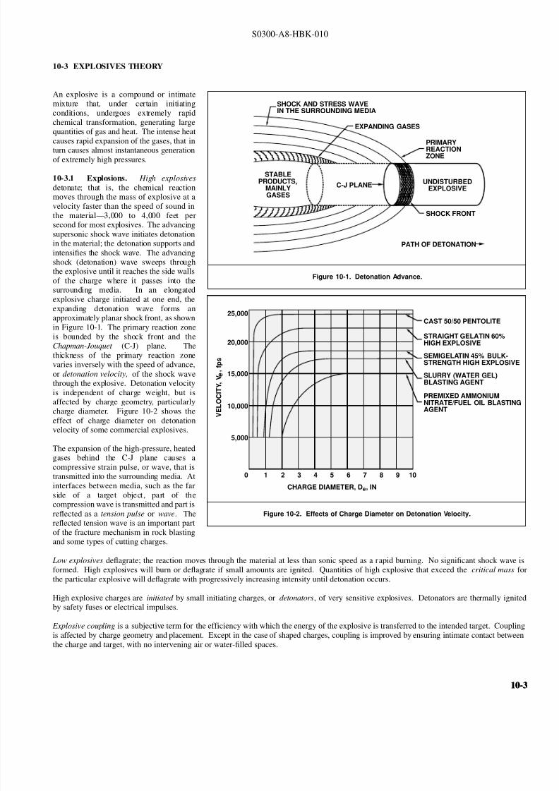
8132019 Articol despre explozii submarine
httpslidepdfcomreaderfullarticol-despre-explozii-submarine 324
S0300-A8-HBK-010
10-3 EXPLOSIVES THEORY
An explosive is a compound or intimate
Figure 10-1 Detonation Advance
SHOCK AND STRESS WAVEIN THE SURROUNDING MEDIA
EXPANDING GASES
PRIMARYREACTIONZONE
STABLEPRODUCTS
MAINLYGASES
SHOCK FRONT
PATH OF DETONATION
UNDISTURBEDEXPLOSIVE
C-J PLANE
mixture that under certain initiatingconditions undergoes extremely rapidchemical transformation generating largequantities of gas and heat The intense heat
causes rapid expansion of the gases that inturn causes almost instantaneous generationof extremely high pressures
10-31 Explosions High explosives
detonate that is the chemical reactionmoves through the mass of explosive at avelocity faster than the speed of sound inthe materialmdash3000 to 4000 feet persecond for most explosives The advancingsupersonic shock wave initiates detonationin the material the detonation supports andintensifies the shock wave The advancingshock (detonation) wave sweeps throughthe explosive until it reaches the side wallsof the charge where it passes into thesurrounding media In an elongatedexplosive charge initiated at one end the
Figure 10-2 Effects of Charge Diameter on Detonation Velocity
25000
20000
15000
10000
5000
0 1 2 3 4 5
CHARGE DIAMETER De IN
V
E L O C I T Y
V e
f p
s
6 7 8 9 10
CAST 5050 PENTOLITE
STRAIGHT GELATIN 60HIGH EXPLOSIVE
SEMIGELATIN 45 BULK-STRENGTH HIGH EXPLOSIVE
SLURRY (WATER GEL)BLASTING AGENT
PREMIXED AMMONIUMNITRATEFUEL OIL BLASTINGAGENT
expanding detonation wave forms anapproximately planar shock front as shownin Figure 10-1 The primary reaction zoneis bounded by the shock front and theChapman-Jouquet (C-J) plane Thethickness of the primary reaction zonevaries inversely with the speed of advance
or detonation velocity of the shock wavethrough the explosive Detonation velocityis independent of charge weight but isaffected by charge geometry particularlycharge diameter Figure 10-2 shows theeffect of charge diameter on detonationvelocity of some commercial explosives
The expansion of the high-pressure heatedgases behind the C-J plane causes acompressive strain pulse or wave that istransmitted into the surrounding media Atinterfaces between media such as the farside of a target object part of thecompression wave is transmitted and part is
reflected as a tension pulse or wave Thereflected tension wave is an important partof the fracture mechanism in rock blastingand some types of cutting charges
Low explosives deflagrate the reaction moves through the material at less than sonic speed as a rapid burning No significant shock wave iformed High explosives will burn or deflagrate if small amounts are ignited Quantities of high explosive that exceed the critical mass fothe particular explosive will deflagrate with progressively increasing intensity until detonation occurs
High explosive charges are initiated by small initiating charges or detonators of very sensitive explosives Detonators are thermally igniteby safety fuses or electrical impulses
Explosive coupling is a subjective term for the efficiency with which the energy of the explosive is transferred to the intended target Couplinis affected by charge geometry and placement Except in the case of shaped charges coupling is improved by ensuring intimate contact betweethe charge and target with no intervening air or water-filled spaces
10-10-
8132019 Articol despre explozii submarine
httpslidepdfcomreaderfullarticol-despre-explozii-submarine 424
S0300-A8-HBK-010
10-32 Properties of Explosives Various properties of an explosive affect its handling employment and ability to perform specific tasks
Detonation velocity is the major property determining an explosiversquos performance characteristics
10-321 Brisance Brisance indicates the relative rate of energy release of an explosive A very brisant explosive produces a rapid pressure
rise and a strong impact Explosives with higher rates of detonation are usually more brisant than slower detonating explosives Steel brittle
rock concrete and other brittle or elastic materials are cut with brisant explosives Less brisant explosives produce less impact can move
objects without shattering them move soft substances such as earth and break plastic materials such as some types of rock
10-322 Relative Effectiveness Relative effectiveness is the ability of an explosive to perform work compared to a standard explosive TNT
is the normal comparison standard The effectiveness of an explosive is referenced to that of TNT by a relative effectiveness (RE) factor (RE TNT
= 1) Formulas for determining charge weight for specific applications are normally referenced to TNT The amount of another explosive
required for the same task is found by dividing the weight of TNT required by the RE factor Blast effect calculations are also based on weights
of TNT An equivalent TNT weight for any explosive is found by multiplying the actual charge weight by the RE factor
10-323 Sensitivity Sensitivity is a measure of the amount of energy required to initiate detonation Primary explosives are very sensitive
Secondary explosives are much less sensitive and usually require the explosion of a small amount of primary explosive to initiate detonation
Sensitivity is not an indication of an explosiversquos power or effectiveness
10-324 Sensitiveness Sensitiveness is the tendency of an explosive to detonate from the impact of a shock wave from another explosion
(sympathetic explosion) It is measured by the maximum distance that an unprimed charge can be detonated by a nearby explosion
10-325 Water Resistance Water resistance is the measure of an explosiversquos resistance to degradation from wetting or immersion Noexplosive is completely water-resistant Most military explosives have good water resistance or are packaged to prevent water from contacting
the explosive
10-33 Underwater Explos ions
Figure 10-3 Pressure-Time History Versus Distance
PRESSURE
INCREASINGDISTANCE
FROMEXPLOSION
EXPLOSIVE
0 infin
TIME
Approximately 40 percent of the energy of
an underwater explosion creates an
expanding gas bubble the remainder is
transmitted to the surrounding water as a
shock wave
10-331 Shock Wave An explosive
shock wave is characterized by a steep
pressure rise with an exponential decay as
shown in Figure 10-3 The shock waveinitially propagates at extremely high speed
but after a few feet speed of propagation
drops to essentially the speed of sound in
watermdashabout 5000 feet per second The
peak pressure (Po) and the initial decay
time constant (θ) at range R are given by
the following formulae
where
Po = 21600
W 13
R
113
θ = 58W 13
W 13
R
022
Po = peak pressure psi
R = range from charge center ft
W = weight of TNT in pounds
θ = initial decay time constant
milliseconds
10-410-4
8132019 Articol despre explozii submarine
httpslidepdfcomreaderfullarticol-despre-explozii-submarine 524
S0300-A8-HBK-010
At range R the shock-wave pressure signature is
where
P = Poe t θ
P = pressure at time t after initial pressure rise Po psi
t = time milliseconds
Peak overpressures in the vicinity of explosions are very high but of very short duration At greater distances from the explosion overpressure
are much lower but of longer duration The total effect of the shock wave is a function of both the peak overpressure and impulse The are
under the pressure decay-time curve in psi-milliseconds is the normal measure of explosive impulse
When a shock wave strikes a solid object part of its energy is transmitted part is absorbed and part is reflected For air-backed membrane
like ship hulls very little of the shock-wave energy is transmitted Pressure loading from the reflected shock wave causes deflection of the hul
The shock-wave pressure soon decreases to zero and cavitation occurs adjacent to the hull Reloading caused by the closing of the cavitatio
reinforced by the waterflow around the expanding and rising gas bubble causes additional deflection Reloading may be many times as sever
as the shock-wave effect alone Reloading is a function of charge depth and slant range and is generally zero for charges at ranges greater tha
twice the charge depth
Most of the shock-wave energy is transmitted through water-backed hulls with only a small amount absorbed and as little as 25 percent of the
deflection of air-backed hulls
10-332 Scaled Distance A principle of similarity applies to shock wave phenomena which permits extrapolation of pressure-time histor
for a given charge weight and distance to another charge weight Given a pressure-time plot at a distance d for a charge W a charge W 1 wi
produce the same plot at a distance kd if the time scale is also multiplied by k where k is the ratio of linear dimensions of the two charges
For example if a 3-pound charge produces a peak pressure of 620 psi at a distance of 47 feet with a time decay curve extending over
milliseconds the distance at which a 1-pound charge will produce the same peak pressure and the associated decay time can be calculated
Since weight is a constant function of volume the volume ratio of the two charges is equal to the weight ratio The volume ratio is the cub
of the linear dimension ratio so
The 1-pound charge will produce a peak pressure of 620 psi at a range of 069336 times 47 = 326 feet The pressure decay curve will extend ove
k =
3W
1
W =
3
1
3= 069336
069336 times 2 = 14 milliseconds To estimate peak pressures for varying distances and charge weights a constant scaled distance can be defined
With the constant r determined for a charge weight yielding a known peak pressure at a specified range the charge weight to give the sam
r = R
3
W
peak pressure at different range or the range at which a different charge weight will give the same peak pressure can be calculated
The scaled distance concept is valid for systems unaffected by outside forces such as gravity Shock waves are essentially unaffected by gravity
but bubble behavior is greatly affected by gravity (buoyancy) Scaled distances cannot be applied to bubble pulses and similar phenomena
10-333 Bubble Pulse The gaseous products of combustion expand to form an approximately spherical bubble The maximum radius of th
gas bubble for charges detonated in free water is given by
Rmax
= 126
W
D 33
13
where
Rmax = maximum gas bubble radius ft
D = charge depth ft
10-10-
8132019 Articol despre explozii submarine
httpslidepdfcomreaderfullarticol-despre-explozii-submarine 624
S0300-A8-HBK-010
The expanding bubble radiates a pressure
Figure 10-4 Gas Bubble Expansion
WATER SURFACE
EXPLOSIVECHARGEIN WATER
ON DETONATIONGASES EXPAND
TO FORM ANAPPROXIMATELY
SPHERICAL BUBBLE
BUBBLE COLLAPESFROM REGION OF
GREATEST PRESSURE(ARROW LENGTHSINDICATE WATER
VELOCITY)
BUBBLE EXPANDSPRINCIPALLY INONE DIRECTION
(a) (b) (c) (d)
Figure 10-5 Pressure-Time Signature 60 Feet from 300-PoundTNT Charge Detonated in Deep Water
SHOCK WAVE
FIRSTBUBBLEPULSE
1770 LBIN2
80 LBIN2Po
O SEC O69 SECTIME
APPROX 100 microSEC
P R E S S U R E
pulse that is less intense than the initial
shock wave but is still significant The
expanding gases cause a rapid outflow of
water that continues temporarily after the
gas pressure and water pressure equalize
because of the waterrsquos momentum The
continued expansion causes pressure in thebubble to drop below ambient hydrostatic
pressure The inward pressure differential
soon causes a reverse flow and the bubble
is recompressed The bubble collapses
away from the region of greatest pressure
as shown in Figure 10-4 The momentum
of the moving water compresses the bubble
beyond equilibriummdashthe bubble will
expand again creating a second weaker
bubble pulse The cyclic expansion and
contraction of the gas bubble with
attendant pressure pulses continues through
several oscillations or until the bubble vents
at the surface Usually only the first pulseis significant At the end of the first bubble
contraction 84 percent of the energy
released by the explosion has been
transmitted to the surrounding water By
the end of the second contraction the
bubble has lost 92 percent of the original
energy Water depth and the proximity of
boundary surfaces influence the form and
movement of the bubble Buoyancy causes
the bubble to rise but hydrodynamic forces
drive it toward rigid surfaces and away
from the water surface The time required
for the expansion-contraction cycle varies
with charge weight and explosive typeranging from 002 to 07 seconds Bubble
pulses are likely for detonations at depths
greater than 25 feet For small charges
(less than 2 frasl 3-pound) two bubble pulses
have been observed for charges in as little as
four feet of water
Peak pressure from the first bubble pulse is less than 20 percent of that of the shock wave but duration is much greater areas under the two
pressure-time curves are comparable Figure 10-5 shows pressure-time signature at a distance of 60 feet from a 300-pound TNT charge fired
50 feet below the surface in deep water The bubble pulse strikes after the initial shock wave and may cause reloading and additional damage
Bubble pulse reloading is somewhat mitigated when charges are detonated alongside a hull The effects can be further mitigated by selecting
a charge weight that produces a maximum bubble radius significantly less than the minimum distance between the charge and the hull The
maximum charge weight for a given bubble radius is found by solving the bubble radius formula for charge weight
W = R 3
126 D 33
where
W = charge weight lbs TNT to create a bubble of radius R ft
D = charge depth ft
10-610-6
8132019 Articol despre explozii submarine
httpslidepdfcomreaderfullarticol-despre-explozii-submarine 724
S0300-A8-HBK-010
Gas bubbles from charges under or near a
Figure 10-6 Seafloor Geometry Likely to Focus Explosive Energy
CHARGE HARDBOTTOM
ship may collapse adjacent to the hull platingas they rise Pressure pulses from bubblescollapsing near the hull may cause damagemore severe than the initial shock wave andreloading If the bubble rises to a positionvery close to the hull it may collapse andimpact the hull with a water hammer Thesebubble effects are of special concern becausehydrodynamic forces cause bubbles tomigrate toward hard surfaces
For charges on the seafloor or in shallowwater the pressure wave and energy trans-mitted through the water may increase overthe free water values The increase de-pends on the rigidity of the seafloor Veryhard seafloors reflect a large percentage of the energy of incident shock wavesmdashtheenergy available for damage may beincreased 50 percent Very irregularseafloors can focus the shock waves causing very high local overpressures Figure 10-6 shows a geometry where shock-wave focusing is likely
In addition to hull damage the sudden velocity imparted to the hull by the shock wave may cause shock damage to machinery electronics another shipboard equipment Equipment may be exposed to accelerations of several hundred to a thousand gravities (grsquos) even when hull damag
is not serious Shock load intensity is indicated by a shock factor defined in Paragraph 10-341
10-34 Blast Effects of Underwater Explosions Effects on structures personnel and marine life depend on peak overpressure and impulseOverpressure and impulse at a distance from the blast have been related to charge weight distance from the charge water depth depth to thecharge and depth to the target Empirical relations based on charge weight and other factors predict blast effects
Blast effects can be estimated with fair accuracy in deep water where pressure waves reflected from the bottom do not affect pressure levelsignificantly In shallow water bottom-reflected waves alter blast effects in an unpredictable manner because of variations in seaflootopography Ridges and other features can cause shadow zones of low overpressures Reflection from hard seafloors or hard strata under thisoft layers will generally increase overpressures and can focus shock waves to produce exceptionally high local pressures Hard dense materialreflect shock waves and transmit ground vibrations more efficiently than soft seafloors These effects are not readily quantified and must bestimated subjectively
10-341 Structural Effects The hull damage to a ship is a function of an empirically derived damage factor defined as the square root of W Rthe damage factor where W is the charge weight (in equivalent pounds of TNT) divided by the slant rangemdashthe straight line distance betweethe hull and the charge Figure 10-7 (Page 10-8) shows curves of the damage factor ( radicWR) as a function of the charge depth to range ratio ( D R
for three nominal hull thicknesses and two categories of damage Light damage is
1
frasl 2
-inch to 1-inch deflection between stiffeners little if anbuckling of stiffeners and no damage to main bulkheads (ie damage that would not require repair) Moderate damage is 1-inch to 2-incpermanent deflection between stiffeners with minor buckling of stiffeners and bulkheads To find charge weight the appropriate curves are enterewith the charge depth to range ratio D R to find the square root of W R corresponding to the hull thickness The equivalent TNT charge weighW can then be found The curves are generally applicable only for charge weights greater than 10 pounds at distances greater than 10 feet fromthe ship If a charge weight of less than 10 pounds or the slant range is less than 10 feet the small charge formula below applies
For small charges detonated at close range the charge weight that will rupture curved stiffened plating is an empirical function of range materiastrength plating thickness and stiffener spacing
W =
(68 times 106)(σt 3 )
1 -
2 R
l
1 + 2 Rl
2
where
W = charge weight to initiate rupture lbs of TNTσ = plating yield strength psit = plating thickness in
R = slant range center of charge to outer plating surface inl = stiffener spacing in
The small charge formula was developed from tests on submarine hull mockups in deep water it should be applicable to any stiffened platstructure but there is no supporting data
10-10-
8132019 Articol despre explozii submarine
httpslidepdfcomreaderfullarticol-despre-explozii-submarine 824
S0300-A8-HBK-010
The shiprsquos critical machinery and cargo
Figure 10-7 Damage Factors
DR
DR
(b) MODERATE DAMAGE
(a) LIGHT DAMAGE
34 PLATE
34 PLATE
12 PLATE
12 PLATE
14 PLATE
14 PLATE
0
0
01
01
02
02
03
03
W
W
R
R
04
04
05
05
06
05
05
06
06
07
07
08
08
09
09
10
10
11
11
12
12
= CHANGE WEIGHT lbs TNT
= SLANT RANGE
= CHARGE DEPTH
= DAMAGE FACTOR
w
R
D
WR
near the detonation area may be damagedby shock-induced motions For chargesless than 20 pounds only small hull-mounted equipment in the immediate areaof the detonation is likely to suffer damageThe degree of shock damage to be expectedis estimated from the shock factor Theshock factor at the point on the hull nearestthe charge is computed from
where
Shock Factor(SF) = W
R
1 + sinφ2
R = slant range ftW = equivalent TNT charge
weight lbs = charge weight times RE factor
φ = angle between the shortestline from the hull to thecharge and a tangent to the
hull at the point nearest tothe hull as shown in Figure10-8
To determine the allowable charge weightan appropriate shock factor is selected fromTable 10-1 to solve for W
10-342 Linear Charges Linear
W = 4(SF)2 R 2
(1 + sinφ)2
demolition charges are frequently used insalvage Line charges produce a complexpressure field In a horizontal plane arounda freely suspended straight line chargemaximum peak pressures occur about 120degrees from the detonation end of thecharge Pressure decay time is about thesame for a given range regardless of orientation relative to the charge axisPressure-time histories on a vertical planeperpendicular to the line charge are quitesimilar to those for a compact charge of same weight with slightly higher peak pressures (2000 psi at 35 feet from acompact 50 pound charge as opposed to2400 psi at 35 feet from a 25 foot linearcharge with 50 pounds of explosive) Table
Table 10-1 Degree of Damage for Various Shock Factors
Shock Factor Damage
lt01 Insignificant ndash nuisance damage only l ight bulbs fuses etc
01 - 015 Tube relay fuse and light bulb failures general electronic failures piping leaks
and possibly a pipe rupture
015 - 020 Increase in above damage piping ruptures likely machinery misalignments likely
020 General machinery damage
10-2 shows the horizontal distribution of peak pressure at distance of 20 feet from
the midlength of a Navy Mk 8 Mod 2 hosecharge (25-foot rubber hose filled with 50pounds of a 7030 mixture of compositionA-3 and aluminum powder) detonated whilefreely suspended 10 feet below the watersurface in approximately 40 feet of water
10-810-8
8132019 Articol despre explozii submarine
httpslidepdfcomreaderfullarticol-despre-explozii-submarine 924
S0300-A8-HBK-010
In An Exploratory Investigation of the
Figure 10-8 Geometry for Calculating Shock Factor
CHARGE
R
φ
Effects of Underwater Line Charges onShip Plating Naval Ship Research andDevelopment Center December 1967 JKFleming and RE Oliver report that thedeflection of hull plating between stiffenerscaused by Navy Mk 8 Mod 2 hose chargescan predicted approximately by
where R t W and σ are as previously
d = 37 a
Ro σ t
2WLRo
4 R2
o L 2
defined and
d = plating set deflection in L = charge length fta = e ff ec ti ve p la ti ng s iz e
(between stiffeners) in
Table 10-2 Pressure Distribution Around Mk 8 Mod 2 Hose Charge
Gage position (angle between line from gage to midlength
and charge axis with detonation end at 0 degrees)
Peak Pressure
psi20 1300
30 1500
40 1730
50 2100
60 2600
70 3300
80 3730
90 3900
100 4220
110 4620
120 5000
130 4000
140 3960
150 2390
160 2250
170 2400
180 3050
All pressures measured 20 feet from midlength of charge
For rectangular plates effective plating sizeis determined from
where
a = 116
90
1
x 2
1
y 2
x = plate width in y = plate length in
10-343 Multiple Charges Multiplecharges detonated simultaneously aretreated as a single large chargemdashthe totalweight of all charges in the array must beless than the maximum acceptable chargeweight determined as described inParagraph 10-341 for a single charge
For multiple charges detonated individuallywith delays between detonations themaximum acceptable single charge weightis determined Charge weights should be
Figure 10-9 Minimum Delay Between Detonations in Charge Array
CHARGE DEPTH FEET
55 LBS TNT
35 LBS TNT
20 LBS TNT
10 LBS TNT
5 LBS TNT D E
L A Y
T I M E
S
E C O N D S
0
05
10
15
20
25
30
10 20 30 40 50 60
one-third the single charge weight or less toprevent progressive hull damage Aminimum delay time between detonations isnecessary to allow the energy from theprevious detonation to dissipate so structureblast loading is not cumulative Minimumdelay times are taken from Figure 10-9
10-344 Ballasting Water-backed hullsare more resistant to shock damage thanair-backed hulls When internal waterdamage is not a problem and the ship can
contain the water spaces in the vicinity of explosive charges may be ballasted How-ever the first air-backed bulkhead exposedto the explosive loading can incur damageif it is in close proximity to the charge
It is not necessary to flood exactly to thewaterline to increase shock resistance butthere should be several feet of water in anyballasted space and six inches to one foot of air between the water surface and the nextdeck No reliable data are available forpredicting how much the charge weight maybe increased if the ship is ballasted A large bubble collapsing near the hull can cause considerable damage even to water-backed plating
10-10-
8132019 Articol despre explozii submarine
httpslidepdfcomreaderfullarticol-despre-explozii-submarine 1024
S0300-A8-HBK-010
10-35 Effects on Marine Life Environmental protection agencies may require salvors to estimate blast effects on local marine life Lethal
ranges may be specified that will limit charge weight
Lethal range seldom exceeds 650 feet and is estimated by
Table 10-3 Fish Kill Range Constants
Fish Weight Depth of Blast ft K
α
1 oz 10 328 0220
1 oz 50 385 0256
1 oz 200 475 0262
1 lb 10 174 0264
1 lb 50 235 0275
1 lb 200 272 0299
30 lbs 10 86 0284
30 lbs 50 131 0314
30 lbs 200 139 0342
H MAX = KW α
where
H MAX = maximum horizontal range of lethal overpressures
feet
K α = coefficients from Table 10-3
W = charge weight pounds
Although fish kill range can be estimated it is very difficult to keep
fish out of a specified area Bubble screens have been used with
some success
10-36 Safe Distances for Above-water Blasts The minimum
distances to protect personnel against shock wave and overpressure
are
SD = 300 W 13
Bare charges on or in ground
SD = 350 W 13
Charges in rock
where
SD = safe distance ft
W = charge weight lbs TNT = W times RE factor
Fragments and debris may be thrown greater distances and hazard personnel in the open The projectile hazard can be reduced by
bull Greater separation distances
bull Confinement of the explosion at the source
bull Barricades between personnel and the blast site
bull Evacuation of nonessential personnel
bull Overhead cover
10-1010-10
8132019 Articol despre explozii submarine
httpslidepdfcomreaderfullarticol-despre-explozii-submarine 1124
8132019 Articol despre explozii submarine
httpslidepdfcomreaderfullarticol-despre-explozii-submarine 1224
S0300-A8-HBK-010
10-41 Charge Weight Charge weight selection is based on two criteria
bull The charge must be large enough to perform the task
bull The charge must not be so large that it causes unacceptable damage to the casualty nearby structures or the environment
The minimum charge weight that will accomplish the task (in one shot) may be greater than the maximum charge weight what will not causedamage It is usually possible to perform the task in a series of steps each using charge weights smaller than the maximum acceptable weight
10-42 Underwater Blasting Water
Figure 10-11 Shared Charge Cutting Sequence
EXPLOSIVECHARGE
CONTAINER
LINER
CAVITY
SHAPEDCHARGE
(a)
S T A N D
- O F F
DETONA-TION WAVEAPPROACHESCAVITY LINER
(b)SHOCK WAVECOLLAPSESLINER INDUCINGJET FORMATION
(c)
CUTTING JETAPPROACHESTARGETSURFACE
(d) PLASTIC FLOW
IS INDUCED INTHE TARGETMATERIAL ANDTHE JET STARTSTO PENETRATE
(e)
JET PASSESTHROUGHTHE TARGET -CUT ISCOMPLETE
(f)
INITIATORpressure on the side of an object oppositethe explosive blast opposes the impact andexpansion of the explosive When the work involves moving large surface areasresistance to movement caused by waterpressure and hydrodynamic drag issignificant and explosive effectiveness isreduced For example it takes about onepound of explosive to break up and move acubic yard of rock in dry air Two to sixpounds of explosive per cubic yard arerequired to break and move the same rock underwater Explosive effectiveness is
further reduced as depth increases
Steel cutting by ribbon charges shapedcharges etc where little surface movementis required is not significantly affected byimmersion in water Shaped chargeeffectiveness is reduced if water cannot bedisplaced or evacuated from the cavity andstand-off (shaped charges are discussed inParagraph 10-421)
Most explosives detonate satisfactorilyunder water Some explosives containwater-soluble ingredients and aredesensitized with time when immersedunless sealed in waterproof containers
Certain explosives depend on dispersed microscopic air or gas bubbles for ease of initiation Immersion in deep water compresses the bubblesand renders them ineffective so they can be used only in shallow water or if specially formulated for deep water use Explosives dependingon dispersed bubbles for initiation include those based on or sensitized by nitroglycerine and nitroglycerol such as gelignites and blastinggelatins and those containing aqueous solutions of ammonium nitrate such as water gels and emulsions
Most military high explosives and commercial explosives based on PETN RDX and TNT can be used reliably in deep water because theyare not are not significantly water-soluble and do not depend on gas bubbles for initiation
Overlying water is an effective tamping agent but if the charge is not in intimate contact with the target the intervening water layer will largelynegate the tamping effect Even a thin water layer between the charge and target will dissipate some of the explosive energy before it reachesthe target The shock and compression waves pass through two media interfacesmdashexplosive to water and water to target energy is reflectedaway from the target at each interface If charges cannot be placed in intimate contact with the work additional tamping in the form of sandbags clay or soil should be used to overcome the dissipation of energy by the intervening water
Potential water tamping lends a slight theoretical advantage to blasting from the wet side of a hull but offsetting advantages accrue whenexplosives are placed in the dry
bull Explosives fuses and initiators are not subject to the desensitizing effects of water immersion or to disturbing forces of currentand surge
bull Charges can be placed more effectivelymdashit is easier to secure charges and intimate contact with the target surface can be attained
bull Charges and firing circuits can be inspected immediately before firing
bull There is greater control over the personnel placing explosives and their work can be monitored and inspected with less effort
Immersion time prior to firing should be minimized to reduce the desensitization of the explosives and the possibility that current or surge willdislodge charges or initiating circuits
10-1210-12
8132019 Articol despre explozii submarine
httpslidepdfcomreaderfullarticol-despre-explozii-submarine 1324
S0300-A8-HBK-010
10-43 Cutting and Fracturing Charges A principal use of explosives in salvage is cutting hull plating and structure in ships High-velocitybrisant explosives such as TNT and plastic explosives are best for cutting steel or aluminum Structural members are cut by a variety ocharges
bull Shaped charges ndash A lined or unlined cavity in the explosive produces a high-energy cutting jet
bull Fracturing charges ndash Specialized charge geometry causes convergence of strain waves in the target
bull Simple contact charges ndash Breakage is accomplished by the combined but uncoordinated effects of shock waves strain pulses angas expansion
Shaped and fracturing charges are far more efficient than contact charges and should be used when available and when suited to working conditions Because of their relatively small charge weights shaped and fracturing charges must be placed precisely and must be held in positioagainst current or surge to be effective If charges cannot be placed precisely better results may be obtained with less efficient contact charge
10-431 Shaped Charges A hollowed-
Figure 10-12 Typical Shaped Charges for Salvage Work
FLEXIBLE LINEARSHAPED CHARGE
BOX TYPELINEAR CHARGE
EXPLOSIVE
TARGET
CASE
METALLINER
ENCLOSED
STAND-OFFSPACE
CYLINDRICALCHARGE
EXPLOSIVECORE
DENSEFLEXIBLE
SHEATH
WOODENSPOOL
out or shaped charge detonated against ahard surface produces a crater that isapproximately a mirror image of the chargecavity The shaped charge is initiated at apoint behind the cavity the detonation waveexpands omnidirectionally from theinitiation point or axis Reaching the cavitythe detonation wave converges on a plane
(for linear charges) or axis (in cylindricalcharges) perpendicular to the target surfaceThe convergence of the shock waveconcentrates the explosive energy in a smallarea The resultant cratering is called the
Munro Effect If the charge is lined withmetal or other dense material the explosioncollapses the liner and carries it in the shock wave to the target surface as a slug (orblade) of metal and hot gas that acts as acutting jet The jet heats and erodes thetarget surface Shock-wave pressure and jeteffects combine to induce plastic flow in thetarget and cut through the material Figure10-11 illustrates the cutting sequence for alined shaped charge
For optimum effect shaped charges arepositioned at a stand-off distance from thetarget surface to allow the penetration jet toform completely before it reaches the targetsurface Optimum stand-off varies with thecavity angle and charge size stand-off isd et er m in ed f r om t ec hn ic al o rmanufacturerrsquos data for the charge used
Various-sized cylindrical shaped chargesare made for hole cutting Linear chargesare used for long cuts Linear charges areusually made in the form of a box with thecavity liner set across the inside of the boxas shown in Figure 10-12 Flexible linearshaped charges can conform to irregular
surfaces and cut lines Well-designedlinear cutting charges obtain good resultswith relatively small charge weightsIndividual charge weight and explosiversquosconsumption are based on data publishedfor the particular explosives used Data formilitary shaped charges is given in the Technical Manual for the Use of Explosives in Underwater Salvage (NAVSEA SW061-AA-MMA-010Typical manufacturerrsquos data for linear shaped charges are shown in Figure 10-13 (Page 10-14)
10-110-1
8132019 Articol despre explozii submarine
httpslidepdfcomreaderfullarticol-despre-explozii-submarine 1424
S0300-A8-HBK-010
Shaped charges can be improvised as
Figure 10-13 Typical Manufacturerrsquos Data for Linear Shaped Charges
STAND-OFF FOR OPTIMUM PERFORMANCE(RDX OR PETN EXPLOSIVE)
MINIMUM CUTTING PERFORMANCEAT OPTIMUM STAND-OFF
MINIMUM CUTTING PERFORMANCEAT OPTIMUM STAND-OFF
MINIMUM CUTTING PERFORMANCEAT OPTIMUM STAND-OFF
MINIMUM CUTTING PERFORMANCEAT OPTIMUM STAND-OFF
5
30 15
10
05
02
01
2010
JETCORDSTAND-OFFTARGET
05
02
01
05
0201
01
02
05
01
02
01
02
05
10
20
02
05
01
02
05
10
1 0
2 0
3 0
4 0
5 0
1 0 0
2 0 0
EXPLOSIVE CORELOAD GRAINSFOOT
EXPLOSIVE CORELOAD GRAINSFOOT
EXPLOSIVE CORELOAD GRAINSFOOT
EXPLOSIVE CORELOAD GRAINSFOOT
NOTE CUTS AT 7 AND 10 GRFTMADE AT ZERO STAND-OFF
EXPLOSIVE CORELOAD GRAINSFOOT
100
5
5
10
10
50 100 200 500 1000
20
20
50
50
100
100
200 500
200 500 1000 2000 5 0 0
S T A N D
- O F F I N C H E S
T H I C K
N E S S
C U T
I N
C H E S
T H I C K N E S S
C U T
I N
C H E S
T H I C K N E S S
C U T
I N
C H E S
T H I C K N E S S
C U T
I N
C H E S
1 0 0 0
2 0 0 0
A L U M
I N U M
S H E A
T H
C O P P
E R S H E A
T H
L E A D
S H E A
T H
C 1 0 1 8 S T E E
L T A R G
E T
COPPER-SHEATHEDJETCORD (RDX ORPETN EXPLOSIVE)
LEAD-SHEATHEDJETCORD (RDX ORPETN EXPLOSIVE)
2024-T351ALUMINUM
TARGET
C10118STEELTARGET
2024-T351ALUMINUM
TARGET
C10118STEELTARGET
ALUMINUM-SHEATHEDJETCORD (RDX
OR PETN EXPLOSIVE)
SILVER-SHEATHEDJETCORD
(DIPAMEXPLOSIVE)
CUT7075-T6
ALUMINUMTARGET
OPTIMUMSTAND-OFF
shown in Figure 10-14 When performance
data for a particular material is not
available cutting ability can be estimated
from the following
where
t = t o
ρρ
o
t = unknown cutting capacity
(thickness) in material of
density ρt o = known cutting capacity in
material of density ρo from
manufacturerrsquos data
Water in the stand-off and cavity prevents
the formation of the cutting jet Theenclosed stand-off of box-type shaped
charges excludes water but boxes can
withstand hydrostatic pressures only to
shallow depths that vary with the particular
unit For depths of 30 to 60 feet the stand-
off can be filled with closed-cell plastic
foam The foam inhibits jet formation
slightly so that performance is decreased
For deeper immersion the stand-off and
cavity must be constructed to withstand
hydrostatic pressure or made free flooding
and then evacuated with compressed air or
gas at depth For underwater use flexible
linear charges can be enclosed in flexibletubes filled with foam or evacuated by
compressed gas One manufacturer markets
a line of circular cutters prefabricated with
compressed gas fittings
10-432 Fracturing Charges A diamond-shaped sheet of plastic explosive laid on a steel plate and detonated simultaneously from two
opposite corners will fracture the metal along a line between the two uninitiated corners This effect is shown in Figure 10-15(a) The fracture
mechanism depends on the pressure rise as the shock waves from the two detonating points collide followed by the relaxation as the waves
pass through one another and the combined effect of two tension waves rebounding from the far side of the target This arrangement is a
diamond charge and is suitable for cutting bars and pipes but has limited application for plate cutting because the fracture extends only slightly
beyond the charge
The diamond charge principle was first applied to extended plate cutting in fracture tape Fracture tape shown in Figure 10-15(b) consists of
a series of diamond charges connected by continuous strips of explosive along the edges of the charges Fracture tape has seen only limiteduse because it was not manufactured in a flexible form The charge may fail to cut if bilateral asymmetry develops between the two initiation
trains Fracture tape can be improvised by cutting explosive sheet to the appropriate shape
Shock-wave refraction tape (SRT) is a recently developed explosive charge that works on the principle of shock-wave collision within metal
targets In this charge a continuous strip of explosive is molded to the back of an inert wave-shaping element as shown in Figure 10-15(c)
One manufacturer uses magnetic rubber as the wave-shaping element providing both flexibility as well as an attachment method (provided the
surfaces are clean and smooth) The performance of shock-wave refraction tape is comparable to that of shaped charges when cutting ordinary
steels very high strength fracture-resistant steels may not be cut as easily There is no cavity or stand-off to flood so SRT is more adaptable
to underwater use than linear shaped charges
10-1410-14
8132019 Articol despre explozii submarine
httpslidepdfcomreaderfullarticol-despre-explozii-submarine 1524
S0300-A8-HBK-010
Figure 10-14 Improvised Shaped Charges
SHEETEXPLOSIVE
STEEL ORALUMINUM
ANGLE
PLASTICEXPLOSIVE
PLASTICEXPLOSIVE
CONE
WINEBOTTLE
STICKS TAPEDTO SIDE ASSTAND-OFF
FUSE
CAP
S T A N D - O
F F
D I S T A N C E
FOOD CANWITH BOTHENDS CUT
OUTPLASTICEXPLOSIVE
SHEETMETALOR LEADSHEETCONE
RIVET
SIDES OFCAN FORMSTAND-OFF
CAP
80˚ - 90˚
Figure 10-15 Fracturing Charges
A
Arsquo
A ArsquoEXPLOSIVE
FRACTURE
EXPLOSIVESHOCK-WAVEFRONTS
REFLECTEDTENSION WAVE
(a) DIAMOND CHARGE (INITIATED AT POINTS A AND Arsquo)
(c) SHOCK-WAVE REFRACTION TAPE (SRT)(b) FRACTURE TAPE
EXPLOSIVE
INERT BARRIERSINITIATION POINT
EXPLOSIVE
WAVE-SHAPINGELEMENT
FRACTURES TENSIONWAVE
SHOCK WAVE
10-110-1
8132019 Articol despre explozii submarine
httpslidepdfcomreaderfullarticol-despre-explozii-submarine 1624
S0300-A8-HBK-010
10-433 Contact Charges Simple
Figure 10-16 Steel Cutting Contact Charges
DETONATINGCORD
EXPLOSIVE
STEEL PLATE
WELDS
STEELCHANNEL
STUD
PLATE
SECURINGSTRAP
EXPLOSIVESHEET OR
PLASTICEXPLOSIVE
contact charges require much heaviercharges than shaped or fracturing chargesExplosive performance can be increasedand charge weight reduced by carefulcharge placement confinement tampingand by scoring cut lines with cuttingtorches or mechanical cutters Some
effective charge placements and geometryare shown in Figure 10-16
Charge weights can be estimated from thefollowing relationships
where
W = 3
8 A Structural steel
W = D 2 High carbon or alloy steel
W = charge weight lbs TNT
A = cross-sectional area of sectionto be cut in2
D = diameter or thickness of section to be cut in
To determine charge weights for explosivesother than TNT the TNT charge weight isdivided by the relative effectiveness (RE)factor
10-434 Charge Placement Cutting charges are most effective when the cut line is adjacent to but not on a rigid portion of the target surfaceThe target must be restrained from moving away from shaped and fracturing charges so the explosive energy is expended in cutting or fracturingthe target rather than pushing it away Contact charges create a strong shearing action along the line between the movable and rigid surfaceHull cutting charges are most effective when slightly offset from frames
bull If placed in the middle of the span a large portion of the explosive energy is expended in deflecting the plate
bull If placed directly over a stiffener both the stiffener and the plate must be cut
For efficient cutting charges must be placed in intimate contact with the target surface Charges must be secured to all vertical steeply angledand overhead surfaces and to horizontal surfaces where current wind vibration or target movement may dislodge them Where no tie-downpoints exist the following securing methods can be used
bull Light metal straps bolted to studs explosively set or friction welded along each side of the cut line
bull Tie-down wires lines or bongee cords inserted through holes cut drilled or burned through the plating (tie-downs can also beled to studs or magnetic clamps)
bull Sandbags or similar weights placed on charges on horizontal surfaces
bull Backing charges with magnetic strips adhesive strips or small suction pads (these methods have had limited success)
bull Hose charges can be stretched between tie-down points over flat or smoothly convex surfaces
10-435 Ship Sectioning Explosives are commonly used to section wrecks for piecemeal removal or to separate a casualty into two piecesso that one part can be salvaged Ship sectioning including explosive methods is discussed in the US Navy Ship Salvage Manual Volume 2(S0300-A6-MAN-020) The following notes supplement that discussion
10-1610-16
8132019 Articol despre explozii submarine
httpslidepdfcomreaderfullarticol-despre-explozii-submarine 1724
S0300-A8-HBK-010
When cutting a ship transversely the internal structure must be cut as well as the more accessible hull plate and stiffeners It is very difficu
to obtain complete separation in a single shot Salvors should plan to make cuts in several shots or have thermal or mechanical cutting gea
available to sever stubborn structure
In a landmark operation in 1973 the salvageable aft section of a 960-foot laden ore carrier was explosively separated from the forward part o
the ship which was abandoned The ship had sunk by the bow in 130 feet of water With holds 7 8 9 and 10 their associated wing and
double-bottom tanks and the machinery spaces dry the after section was buoyant and afloat The hull was cut in way of number 7 hold b
more than 1800 feet of custom engineered and fabricated high speed explosive cutters All cutters were placed in the dry number 7 wing anbottom tanks Instantaneous separation (necessary to prevent capsize of or damage to the aft section) was attained by
bull Placing cutters against all bulkheads shell plating stringers void tank sections and pipes extending through the transvers
bulkhead separating holds 7 and 8
bull Taking advantage of the vertical shear on the hull resulting from the weight of the forward section laden with 90000 tons of ore
and the buoyancy of the after section and
bull Maintaining a 300-ton horizontal astern pull on the after section as the cutters were detonated
Blast curtains were rigged in the number 7 tanks and hold and the number 8 wing and bottom tanks were pressurized with compressed air to
protect the separating bulkhead A diverrsquos survey after the successful separation revealed no damage to the bulkhead The operation was mad
possible by the salvorsrsquo employment of specialist explosives engineers who custom designed the explosive cutters taking into account permissiblblast effects on the aft number 7 bulkhead gas generation and dispersion requirements mutual interference between charges and the strength
of hull structural members See The Cutting of the Igara in Reedrsquos Commercial Salvage Practice for a more detailed discussion of th
operation
The order in which the different members are to be cutmdashas well as the methods to be usedmdashmust be considered carefully Preliminary cut
should not weaken the structure to the point that it is in danger of collapsing and injuring personnel placing charges for subsequent cuts
Cutting methods are frequently combined A hull can be opened up with explosives to permit access to internal structure to be cut by mechanica
or thermal methods In some cases preparatory weakening cuts are made by divers with oxy-arc or exothermic torches with the final cuts mad
explosively
Simple types of ships are better candidates for explosive sectioning than more complex types The following ship types lend themselves t
explosive sectioning
bull Transversely framed ships because there are fewer longitudinal stiffeners to cut
bull Freighters and bulk carriers because most do not have centerline longitudinal bulkheads (some bulk carriers have wing tanks whos
inner bulkheads must be cut) Small ships often do not have double bottoms
bull Small single-product tankers because they do not have wing tanks or double bottoms
The following ship types are not good candidates for explosive sectioning
bull Longitudinally framed ships because of the large number of longitudinal stiffeners
bull Passenger ships and warships because of their extensive joiner work internal subdivision wireways piping and ventilatio
systems
bull Large tankers and product carriers because they are constructed with two or more longitudinal bulkheads
bull Freighters with insulated holds
10-110-1
8132019 Articol despre explozii submarine
httpslidepdfcomreaderfullarticol-despre-explozii-submarine 1824
S0300-A8-HBK-010
10-44 Seafloor Blasting Seafloor
Figure 10-17 Obstruction Blasting
CONTACT BLASTING MUDCAPPING
SNAKEHOLING
STEMMINGSTEMMING
CHARGE
CHARGE
BLOCKHOLING
blasting moves large amounts of seafloor
material by channeling trenching etc or
removes isolated obstructions such as
pinnacles coral heads and boulders The
basic techniques are
bull Contact Blasting ndash Chargesare placed on the formation
to be blasted either indi-
vidually or in line or
checkerboard patterns The
detonating explosive imparts
a violent blow to the seafloor
material The efficiency of
contact blasting depends on
maintaining intimate contact
with the material to be
blasted Contact blasting is
the least efficient blasting
method in terms of explosive
consumption but requires the
least time and effort to
prepare and set charges
bull Boreholes ndash Internal charges
are placed in boreholes
drilled or augured into the
object or strata to be blasted
10-441 Rock Blasting The choice of explosive for a particular rock-blasting job depends on the hardness and density of the rock and the
type of breakage desired Fast brisant explosives such as TNT or composition C-4 are required to break most kinds of rock although slower
explosives are effective on soft rock such as limestone
Rock is weakest in tension so internal charges are most effective Contact blasting depends on the tamping effect of overlying water to confine
the explosion momentarily and is effective only on soft rock and coral where the material is broken by crushing rather than shattering The
rock fragments are moved by the expanding gases so high gas production is required to move dense rock If the object is to break up rock for
removal by nonexplosive means gas production of the explosive is less important Individual boulders are broken by one of the methods
discussed below The methods are illustrated in Figure 10-17
bull Mudcapping ndash A contact charge is covered with 10 to 12 inches of mud clay or moist soil tamping Plastic clay is the most
effective tamping Loose sand should not be used but sandbags are effective
bull Snakeholing ndash The charge is placed in a hole jetted bored or otherwise excavated under an object lying on or partially buried
in a soft seafloor Snakeholing is more effective than mudcapping under all conditions and requires about one-half as much
explosive as contact blasting
bull Blockholing ndash The charge or charges are placed in one or more boreholes Explosive effect can be altered by changing charge
weights and placement rock formations boulders concrete structures etc can be completely demolished be broken into
fragments of varying size or have portions broken off Blockholing requires about one-third as much explosive as contact blasting
Table 10-4 gives approximate explosive requirements in pounds per
Table 10-4 Powder Factors (lbyd3) for Rock Blasting
Blas ting Metho d A ir B la sting Und erwater Blas ting
Contact Blasting Not effective 6 - 20
Mudcapping 1 - 2 4 - 15
Snakeholing 1 - 11 frasl 2 3 - 10
cubic yard or powder factor for different rock-blasting methods A
range of powder factors for each method is given The actual powder
factor for any project will depend on
bull The relative density and toughness of the rock
bull Whether individual boulders or massive rock formations
are being blasted
bull Water depth
10-1810-18
8132019 Articol despre explozii submarine
httpslidepdfcomreaderfullarticol-despre-explozii-submarine 1924
S0300-A8-HBK-010
The lower values in Table 10-4 are based
Table 10-5 Rock Density and Toughness
Type of Rock Density lbft3 Relative Toughness (Limestone = 1)
Andesite 150 - 175 11
Basalt 150 - 200 17 - 23
Conglomerate 125 - 162 NA
Dioritic 156 - 200 19 - 21
Felsite 150 - 200 NA
Gabbro 169 - 200 NA
Granite 156 - 194 15 - 21
Gneiss 150 - 181 10 - 19
Limestone 160 - 187 10
Marble 131 - 181 NA
Quartzite 125 - 200 19 - 27
Sandstone 124 - 194 15 - 26
Schist 150 - 175 10 - 21
Shale 112 - 194 NA
Slate 156 - 194 12
on blasting massive limestone at depths of 30 to 60 feet Values high in the range areused with tougher or denser rocks andgreater depth Lower values are used whenblasting individual boulders or outcrop-pings Table 10-5 compares densities andtoughness of common rocks
Rock blasting by internal charges is mosteffective when there is a free face approxi-mately parallel to the borehole Thedetonation of the explosive creates a highgas pressure in the charge hole generating acompressive strain pulse in the surroundingrock The compressive pulse travels outwardin all directions Near the hole theamplitude of the strain pulse is sufficient tocrush the rock Amplitude decays rapidly asthe pulse travels outward until it can nolonger crush the rock The pulse travels out-ward until it is reflected from a free surfaceas a tensile strain pulse As rock is much
Figure 10-18 Excavation Rock Blasting
DRILLING FACE
WORKING OR FREE FACE
BOREHOLE
BENCH
EXCAVATION FLOOR(PROJECT DEPTH)
L
B
BltL
INSUFFICIENT EXPLOSIVEENERGY RELEASE AT
BOTTOM OF HOLE
B
MAINFRACTURELINES
COLUMN LOADEDHOLE
45˚
STRESS PATTERN FOR ACONCENTRATED CHARGE
IN BOTTOM OF HOLE
REFLECTEDTENSION WAVE
UNREFLECTEDCOMPRESSIONWAVE
TOE
weaker in tension than compression the
tensile pulse is able to break the rock pro-gressing from the free face back towards thecharge hole The expanding gases in thecharge hole are not directly responsible formuch of the rock breakage to some extentthe rock is pulled apart rather than pushedapart
Blasting massive seafloor rock formations issubject to constraints similar to those en-countered in quarry blasting and similarmethods are employed Detailed informationon rock blasting is found in publications onmining and quarrying For effective blastingit is necessary to establish a breaking orworking face at an angle to the drilling faceThe drilling face is most often the horizontalseafloor the working face is vertical orinclined from the vertical by an angle of 45degrees or less The working face is brokenback in steps by detonating charges in rowsof holes behind the face For cuts deeperthan the maximum practical drilling depththe working face is broken back in stages byestablishing intermediate floor levels orbenches as shown in Figure 10-18
A working face can be established in aflush surface by blasting out a crater with asingle charged hole cluster of holes or lineof holes Empty relief holes between andaround charged holes provide free faces toreflect strain pulses and space for displaced
rock to move into The excavation floorand work face can be squared up bysubsequent blasting
Boreholes can be drilled by diver-operated jackhammers or rock drills for smalloperations For extensive drillingoperations a spud-moored drill barge or asubmersible crawler-mounted rock drillshould be used
10-110-1
8132019 Articol despre explozii submarine
httpslidepdfcomreaderfullarticol-despre-explozii-submarine 2024
S0300-A8-HBK-010
10-442 Coral Blasting Coral is difficult
Figure 10-19 Coral Blasting
13
13
12
12
11
11
10
10
9
9
8
8
7
7
6
6
5
5
4
4
3
3
2
2
1
1
0
0
DEPTH AND WIDTH OF CUTS MADE IN CORAL WHEN BLASTING WITH CAVITY CHARGES
DEPTH AND WIDTH OF CUTS MADE IN CORAL BY STANDARDUS MARK 8 DEMOLITION CHARGES
VOLUME OF CORAL REMOVED USING9-KG (20 POUND) CHARGES
CRATER WIDTH IN FEET
CRATER WIDTH IN FEET
NUMBER OF PACKS
V O L U M E
I N
C U B I C
F E E T
1 2 3 4 5
1
1
2
2
3
3
4
4
5
5
6
6
7
7
8
8
9
9
10
10
11
11
12
12
13
13
1
1
2
2
3
3
4
4
5
5
100
20
30
40
50
60
70
80
90
100110
D E P T H
I N
F E E T
D E P T H
I N
F E E T
to blast because of its porosity High-velocity explosives have been successfulbut slow-detonating explosives are moreeffective Coral will clog rock drills sointernal charges are set in powder points(pipes driven into the formation) Powderfactors for coral are about five pounds per
cubic foot for mushroom-shaped coralheads and higher for solid headsDemolition of an above-water coralformation requires about three times asmuch explosive as an equivalent underwaterformation unless a well-placed thoroughlytamped internal charge is used Linecharges can be used to cut trenches orchannels in coral Figure 10-19 showstypical results of coral blasting
10-443 Blasting ImpalementsRemoving an impaling rock or coral head isa slow and tedious process The chargesmust be large enough to break the rock orcoral but light enough that they do not
damage the ship or drive the impalementfurther into the ship The only feasibleprocedure is to begin with very smallcharges and check the results after eachshot Charge size can be increasedincrementally if there is no hull damage orthe same charge can be repeated until theimpalement is gradually severed or brokenaway A large internal concrete patch overthe impalement and surrounding platingstrengthens the hull against shock loadingso that larger charges can be used Theimpalement should be cut off about twofeet below the hull
When external access to the impalement isdangerous or impossible the impalement isattacked from the inside The bestprocedure is to use small charges inshallow boreholes with interspersed relief holes to progressively shatter theimpalement and lower it sufficiently toclear the hull Doors and hatches should beopen during blasting to prevent the hull from being pressurized internally by the explosive gases It may be necessary to build a trunk aroundthe impalement to provide a watertight enclosure and to vent explosive gases to the atmosphere
10-444 Setting Anchors Anchors can be set in hard pan coral clay or mud bottoms with explosives Small charges are set near the anchoras shown in Figure 10-20 and detonated The anchor is lifted and dropped into the blast crater At the same time a quantity of loose or brokenseafloor is lifted out of the crater and some of this material will settle on the anchor Anchors can be explosively settled into seafloors subjectto liquefication under high-frequency cyclic loading such as clean medium- or low-density cohesionless soils A number of small chargesdetonated sequentially on short delay in the vicinity of the anchor can liquefy the soil allowing the anchor to settle into the seafloor underits own weight
10-445 Channeling in Soft Bottoms Military dynamite or other low-velocity low-brisance explosives are best for moving soft plasticmaterial Powder points contact charges charges in augured or excavated holes or hose charges in checkerboard or linear patterns are usedContact blasting will normally dig a channel or crater four to five feet deep Deeper cuts can be attained by driving powder points to the desiredchannel depth plus the distance between points Powder factors are three to five pounds of explosive per cubic yard of soil Alternate pointsshould contain charges of different weights so that the detonation waves do not cancel one another Soft seafloors are almost always excavatedmore effectively by nonexplosive means such as dredging or scouring
10-2010-20
8132019 Articol despre explozii submarine
httpslidepdfcomreaderfullarticol-despre-explozii-submarine 2124
S0300-A8-HBK-010
10-45 Concrete and Masonry Blasting
Figure 10-20 Setting Anchors with Explosive Charges
CHARGESANCHOR
FIRING SYSTEM BLASTING CAP
BUOY
DETONATING CORD MADEUP TO WORKING LINE
LIGHT LINE TO KEEP STRAINOFF DETONATING CORD
Concrete and masonry are blasted by thesame methods as rock Simple concretedispersal requires about one pound of explosive per cubic foot Breachingcharges for concrete and masonry structuresare estimated by
W = R
3
KC where
W = charge weight lbs TNT R = breaking radius ft
= thickness for externalcharges
= distance to outside surfacefor internal charges
K = material factor from Table10-6
C = tamping factor from Figure10-21 (Page 10-22)
10-46 Timber and Pile Cutting Forcutting timber high-velocity brisant
explosives work best but low-velocityexplosives are effective when appliedproperly Charge weights vary as thesquare of the diameter of the timberEmpirical relationships for determiningcharge weights are given below
where
W = D 2
4Untamped external charges
W = D 2
250Tamped internal charges
Table 10-6 Material Factor K for Concrete Breaching Charges
Material R K
Poor masonry shale and hardpan All values 0225
Good masonry ordinary concrete rock
Less than 3 ft
3 to 5 ft
5 to 7 ft
More than 7 ft
035
0275
025
0225
Dense concrete first-class masonry
Less than 3 ft
3 to 5 ft
5 to 7 ft
More than 7 ft
045
0375
0325
0275
Reinforced concrete (concrete only will
not cut reinforcing steel)
Less than 3 ft
3 to 5 ft
5 to 7 ft
More than 7 ft
070
055
050
0425
W = charge weight lbs TNT D = diameter of round or leastdimension of dressedtimber in
For explosives other than TNT chargeweight is determined by dividing the TNTcharge weight by the relative effectiveness(RE) factor
10-47 Reducing Underwater ShockWave Pressure and Impulse Shock waves damage structures by two differentmechanisms
bull The peak shock wave pressureexceeds the compressive strengthof the material
bull The impulse causes structural elements to vibrate with their natural frequency The deflection may be great enough to cause damageImpulse caused vibrations can cause damage even when the peak pressure does not exceed the compressive strength of the material
Shock wave pressure or impulse at a structure can be reduced by charge placement bubble screens and in the case of multiple charges firingsequence
10-210-2
8132019 Articol despre explozii submarine
httpslidepdfcomreaderfullarticol-despre-explozii-submarine 2224
S0300-A8-HBK-010
10-471 Charge Placement Observations
Figure 10-21 Tamping Factor C for Concrete Breaching Charges
C = 45
C = 25 C = 20 - 25
C = 23C = 35
C = 20 C = 15
C = 25
UNTAMPED CHARGES
TAMPED CHARGES
R
R R
R
R
R R
R
t 03tltdltt
D
C = 125C = 125
STEMMED PLACED IN
CENTER OFMASS
C = 125 - 10
R
t dgtt
DR
R
FILL
Figure 10-22 Shock Wave Effects for Various Blasting Conditions
NOTE
620PSI
50PSI
29PSI
14 MS
13 MS
2 MS
(a) 33 FT FROM 1LB CHARGEIN FREE WATER
EXTRAPOLATED FROM DATAFOR POINT 47 FT FROM 3LBCHARGE IN FREE WATER
NOTEEXTRAPOLATED FROM DATAFOR POINT 47 FT FROM 2LBCHARGE IN 29 FT3 OF ROCK
(b) 33 FT FROM 1LBCHARGE IN ROCK
(c) 33 FT FROM 1LB CHARGEIN FREE WATER THROUGHBUBBLE SCREEN(0043 FT3SEC PER FT)
of underwater rock blasting operations haveshown that peak pressures for explosiveswell packed in bore holes is much less thanthat of charges in the water Figure 10-22compares time pressure curves 33 feet froma one pound charge in free water and thesame sized charge in submerged rock Thegreat difference in peak pressures and totalimpulse indicates that a principal means of reducing underwater shock wave effects isto ensure that charges are not detonated whileexposed to free water In seafloor orobstruction blasting internal charges shouldbe used The top portions of boreholes fora distance of 15 times the borehole diametershould be left uncharged Blasting patternsshould be arranged to avoid sympatheticdetonation and ensure that charges to bedetonated later in a firing sequence are notexposed by rock breakage from earlierdetonations Heavy sandbag or clay tampingover cutting charges can significantly reduceshock effects in the surrounding area
10-472 Bubble Screens An impingingshock wave compresses the bubbles of abubble screen over a period of somemilliseconds On their subsequent re-expansion over a period of milliseconds thebubbles emit new compression waves withlower peak values The part of the shock wave that passes between the bubbles isalso attenuated Increasing the number of air bubbles increases the reduction in peak pressure but also increases the duration of the pressure on the side of the bubblescreen away from the blast Investigationsby AT Edwards at the Hydro-electricPower Commission of Ontario showed thatthe peak pressure 33 feet from a one poundcharge was reduced by a factor of 10 by anintervening bubble screen produced by anair flow of 0043 cubic feet per second perfoot of pipe Doubling the air flow reducedpeak pressure by a factor of 70 at the samedistance with the same charge weight At164 feet the corresponding reductionfactors were 8 and 40 Three inchdiameter pipe was used in the experimentswith groups of two diametrically opposite1 frasl 16-inch holes spaced 3 frasl 4-inch or 11 frasl 2 inchesapart Figure 10-22 shows the pressure-time history 33 feet from a one poundcharge with an intervening water curtain
In reducing peak pressure while simultan-eously extending the decay time the bubble
screen redistributes but does not decrease to-tal impulse Bubbles screens are ineffectivein preventing damage in most cases wherethe damage mechanism is primarily impulse
10-473 Firing Sequence In multiple-charge shot-delay shots firing the chargesclosest to the structure to be shielded firstwill reduce the impulse transmitted to thestructure by the delayed charges Theimpulse from the delayed charges is partlyscreened off by explosion gases (and brokenrock when seafloor blasting) from earliercharges
10-2210-22
8132019 Articol despre explozii submarine
httpslidepdfcomreaderfullarticol-despre-explozii-submarine 2324
S0300-A8-HBK-010
10-5 PERMITS
Authorization from the appropriate fleet commander is required for all underwater explosives detonations OPNAVINST 85302 lists the basi
requirements to be met before using demolitions Amplifying instructions in the 8530 series have been issued by fleet commanders
Some of the additional permits required from various Federal and local agencies are described in the following paragraphs It may take man
months to obtain all the required permits Planning for explosives operations should start well in advance and be coordinated carefully so thaall permits are valid over the desired time frame and that other salvage tasks that proceed sequentially or concurrently with the explosive
operations are ready on schedule
10-51 Corps of Engineers Section 10 of the River and Harbor Act of March 3 1899 (30 Stat 1151 33 USC 403) prohibits the obstructio
or alteration of any navigable water of the United States without authorization from the Secretary of the Army Requirements for and limitation
of permits are described in Title 33 of the US Code of Federal Regulations (33 CFR) Article 209120 Detailed information concerning th
permits required for a specific project can be obtained from the local Corps of Engineers Office or from the Department of the Army Offic
of the Chief of Engineers Washington DC 20314
10-52 Environmental Impact Statement Explosives projects that may have an adverse effect on the environment may require the filing o
an Environmental Impact Statement Information on the filing of the statement is found in OPNAVINST 50901 (series)
10-53 State and Local Agencies The number and kind of permits required for explosives operations varies widely from location to location
A partial listing of agencies that may require permits includes
bull State Fish and Game Commission
bull State Lands Commission
bull State Oil and Gas Commission
bull StateEnvironmental Commission Department of Environmental ManagementEnvironmental Protection Agency or similar agency
bull County Board of Supervisors
bull Local police or sheriff
bull Fire Marshal
bull City Engineer
10-6 OPERATIONAL NOTES
10-61 Test Shots Because of the imprecise nature of charge weight and blast effect calculations test shots should always be made before
or at the beginning of an explosives job Test shots are made to determine two quantities
bull The minimum charge weight required to perform the task
bull The maximum charge weight that will not cause unacceptable damage to the casualty nearby structures or the environment
Tests to determine minimum charge weight should be conducted well before the operation at an explosives range or remote site
The maximum acceptable charge weight is estimated by calculation and verified by on-site test shots Test shots are usually conducted as th
first working shots Test shots start with charges lighter than those calculated for the job gradually increasing the charge weights until th
minimum charge weight to perform the task is reached or blast effects become unacceptable
10-210-2
8132019 Articol despre explozii submarine
httpslidepdfcomreaderfullarticol-despre-explozii-submarine 2424
S0300-A8-HBK-010
10-62 Explosives Expertise The importance of seeking the advice of experienced hands for explosives projects cannot be overemphasized
There is no program in the US Navy to train or certify salvage demolitions specialists Navy first class divers and diving officers receive
limited explosives demolitions training Explosive ordnance disposal (EOD) divers and special warfare swimmers (SEAL) receive additional
training in specialized procedures that are not always applicable to salvage The particular demolitions expertise of a Navy diver is a function
of on-the-job experience that may vary from extensive to none In the absence of personnel experienced in salvage demolitions advice may
be sought from Navy Mobile Construction Battalions or the Army Corps of Engineers Commercial explosives consultants may be retained
through the Supervisor of Salvage
10-63 US Military Explosives A wide variety of explosives in various types of demolition charges are maintained in the system for use
by military forces These explosives and charges are described in the Navy technical manuals Use of Explosives in Underwater Salvage
(NAVSEA-SW061-AA-MMA-010) and Demolition Materials (NAVSEA OP 2212) and the Army field manual Explosives and Demolitions (FM
5-25) A summary of the characteristics of US Military explosives is given in Table 10-7
Table 10-7 Characteristics of Military Explosives
Explosive Typical Uses
Rate of Detonation
(Feet per Second)
Relative Effectiveness as
an External Charge
(TNT = 100)
Intensity of
Toxic Fumes
Water
Resistance
Amatol Bursting Charge 16000 fps 117 Dangerous Poor
Ammonium Nitrate Cratering Charge and
Composition Explosives 8900 fps 042 Dangerous None
Black Powder Time Blasting Fuse 1300 fps 055 Dangerous None
Composition A-3 Booster Charge and Bursting
Charge 26500 fps 126 Dangerous Good
Composition B Bursting Charge 25600 fps 135 Dangerous Excellent
Composition C-3 Demolition Charge 25000 fps 126 Dangerous Good
Composition C-4 Demolition Charge 26500 fps 126 Dangerous Excellent
HBX-1 and HBX-3 Demolition Charge 24300 fps Air 148
Underwater 168 Dangerous Excellent
H-6 Demolition Charge 24300 fps Air 148
Underwater 168 Dangerous Excellent
Pentolite 5050
Booster Charge and Bursting
Charge 24600 fps 126 Dangerous Excellent
PETN Detonating Cord Blasting Cap
and Demolition Charge 26000 fps 166 Dangerous Excellent
RDX Blasting Caps Composition
Explosives 27400 fps 160 Dangerous Excellent
Tetryl Booster Charge and
Composition Explosives 23300 fps 125 Dangerous Excellent
Tetrytol 7525 Demolition Charge 23000 fps 120 Dangerous Excellent
TNT Demolition Charge and
Composition Explosives 22500 fps 100 Dangerous Excellent
TNT is used as the standard (TNT = 100) for comparison of the effectiveness of other explosives
10-64 Commercial Explosives A variety of commercial explosives and explosive devices are available including highly effective custom-
made steel cutting charges liquid explosives gelatins etc The Supervisor of Salvage should be contacted if the use of commercial explosives
is indicated
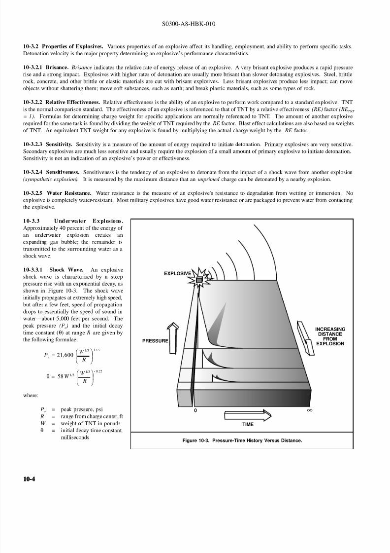
8132019 Articol despre explozii submarine
httpslidepdfcomreaderfullarticol-despre-explozii-submarine 424
S0300-A8-HBK-010
10-32 Properties of Explosives Various properties of an explosive affect its handling employment and ability to perform specific tasks
Detonation velocity is the major property determining an explosiversquos performance characteristics
10-321 Brisance Brisance indicates the relative rate of energy release of an explosive A very brisant explosive produces a rapid pressure
rise and a strong impact Explosives with higher rates of detonation are usually more brisant than slower detonating explosives Steel brittle
rock concrete and other brittle or elastic materials are cut with brisant explosives Less brisant explosives produce less impact can move
objects without shattering them move soft substances such as earth and break plastic materials such as some types of rock
10-322 Relative Effectiveness Relative effectiveness is the ability of an explosive to perform work compared to a standard explosive TNT
is the normal comparison standard The effectiveness of an explosive is referenced to that of TNT by a relative effectiveness (RE) factor (RE TNT
= 1) Formulas for determining charge weight for specific applications are normally referenced to TNT The amount of another explosive
required for the same task is found by dividing the weight of TNT required by the RE factor Blast effect calculations are also based on weights
of TNT An equivalent TNT weight for any explosive is found by multiplying the actual charge weight by the RE factor
10-323 Sensitivity Sensitivity is a measure of the amount of energy required to initiate detonation Primary explosives are very sensitive
Secondary explosives are much less sensitive and usually require the explosion of a small amount of primary explosive to initiate detonation
Sensitivity is not an indication of an explosiversquos power or effectiveness
10-324 Sensitiveness Sensitiveness is the tendency of an explosive to detonate from the impact of a shock wave from another explosion
(sympathetic explosion) It is measured by the maximum distance that an unprimed charge can be detonated by a nearby explosion
10-325 Water Resistance Water resistance is the measure of an explosiversquos resistance to degradation from wetting or immersion Noexplosive is completely water-resistant Most military explosives have good water resistance or are packaged to prevent water from contacting
the explosive
10-33 Underwater Explos ions
Figure 10-3 Pressure-Time History Versus Distance
PRESSURE
INCREASINGDISTANCE
FROMEXPLOSION
EXPLOSIVE
0 infin
TIME
Approximately 40 percent of the energy of
an underwater explosion creates an
expanding gas bubble the remainder is
transmitted to the surrounding water as a
shock wave
10-331 Shock Wave An explosive
shock wave is characterized by a steep
pressure rise with an exponential decay as
shown in Figure 10-3 The shock waveinitially propagates at extremely high speed
but after a few feet speed of propagation
drops to essentially the speed of sound in
watermdashabout 5000 feet per second The
peak pressure (Po) and the initial decay
time constant (θ) at range R are given by
the following formulae
where
Po = 21600
W 13
R
113
θ = 58W 13
W 13
R
022
Po = peak pressure psi
R = range from charge center ft
W = weight of TNT in pounds
θ = initial decay time constant
milliseconds
10-410-4
8132019 Articol despre explozii submarine
httpslidepdfcomreaderfullarticol-despre-explozii-submarine 524
S0300-A8-HBK-010
At range R the shock-wave pressure signature is
where
P = Poe t θ
P = pressure at time t after initial pressure rise Po psi
t = time milliseconds
Peak overpressures in the vicinity of explosions are very high but of very short duration At greater distances from the explosion overpressure
are much lower but of longer duration The total effect of the shock wave is a function of both the peak overpressure and impulse The are
under the pressure decay-time curve in psi-milliseconds is the normal measure of explosive impulse
When a shock wave strikes a solid object part of its energy is transmitted part is absorbed and part is reflected For air-backed membrane
like ship hulls very little of the shock-wave energy is transmitted Pressure loading from the reflected shock wave causes deflection of the hul
The shock-wave pressure soon decreases to zero and cavitation occurs adjacent to the hull Reloading caused by the closing of the cavitatio
reinforced by the waterflow around the expanding and rising gas bubble causes additional deflection Reloading may be many times as sever
as the shock-wave effect alone Reloading is a function of charge depth and slant range and is generally zero for charges at ranges greater tha
twice the charge depth
Most of the shock-wave energy is transmitted through water-backed hulls with only a small amount absorbed and as little as 25 percent of the
deflection of air-backed hulls
10-332 Scaled Distance A principle of similarity applies to shock wave phenomena which permits extrapolation of pressure-time histor
for a given charge weight and distance to another charge weight Given a pressure-time plot at a distance d for a charge W a charge W 1 wi
produce the same plot at a distance kd if the time scale is also multiplied by k where k is the ratio of linear dimensions of the two charges
For example if a 3-pound charge produces a peak pressure of 620 psi at a distance of 47 feet with a time decay curve extending over
milliseconds the distance at which a 1-pound charge will produce the same peak pressure and the associated decay time can be calculated
Since weight is a constant function of volume the volume ratio of the two charges is equal to the weight ratio The volume ratio is the cub
of the linear dimension ratio so
The 1-pound charge will produce a peak pressure of 620 psi at a range of 069336 times 47 = 326 feet The pressure decay curve will extend ove
k =
3W
1
W =
3
1
3= 069336
069336 times 2 = 14 milliseconds To estimate peak pressures for varying distances and charge weights a constant scaled distance can be defined
With the constant r determined for a charge weight yielding a known peak pressure at a specified range the charge weight to give the sam
r = R
3
W
peak pressure at different range or the range at which a different charge weight will give the same peak pressure can be calculated
The scaled distance concept is valid for systems unaffected by outside forces such as gravity Shock waves are essentially unaffected by gravity
but bubble behavior is greatly affected by gravity (buoyancy) Scaled distances cannot be applied to bubble pulses and similar phenomena
10-333 Bubble Pulse The gaseous products of combustion expand to form an approximately spherical bubble The maximum radius of th
gas bubble for charges detonated in free water is given by
Rmax
= 126
W
D 33
13
where
Rmax = maximum gas bubble radius ft
D = charge depth ft
10-10-
8132019 Articol despre explozii submarine
httpslidepdfcomreaderfullarticol-despre-explozii-submarine 624
S0300-A8-HBK-010
The expanding bubble radiates a pressure
Figure 10-4 Gas Bubble Expansion
WATER SURFACE
EXPLOSIVECHARGEIN WATER
ON DETONATIONGASES EXPAND
TO FORM ANAPPROXIMATELY
SPHERICAL BUBBLE
BUBBLE COLLAPESFROM REGION OF
GREATEST PRESSURE(ARROW LENGTHSINDICATE WATER
VELOCITY)
BUBBLE EXPANDSPRINCIPALLY INONE DIRECTION
(a) (b) (c) (d)
Figure 10-5 Pressure-Time Signature 60 Feet from 300-PoundTNT Charge Detonated in Deep Water
SHOCK WAVE
FIRSTBUBBLEPULSE
1770 LBIN2
80 LBIN2Po
O SEC O69 SECTIME
APPROX 100 microSEC
P R E S S U R E
pulse that is less intense than the initial
shock wave but is still significant The
expanding gases cause a rapid outflow of
water that continues temporarily after the
gas pressure and water pressure equalize
because of the waterrsquos momentum The
continued expansion causes pressure in thebubble to drop below ambient hydrostatic
pressure The inward pressure differential
soon causes a reverse flow and the bubble
is recompressed The bubble collapses
away from the region of greatest pressure
as shown in Figure 10-4 The momentum
of the moving water compresses the bubble
beyond equilibriummdashthe bubble will
expand again creating a second weaker
bubble pulse The cyclic expansion and
contraction of the gas bubble with
attendant pressure pulses continues through
several oscillations or until the bubble vents
at the surface Usually only the first pulseis significant At the end of the first bubble
contraction 84 percent of the energy
released by the explosion has been
transmitted to the surrounding water By
the end of the second contraction the
bubble has lost 92 percent of the original
energy Water depth and the proximity of
boundary surfaces influence the form and
movement of the bubble Buoyancy causes
the bubble to rise but hydrodynamic forces
drive it toward rigid surfaces and away
from the water surface The time required
for the expansion-contraction cycle varies
with charge weight and explosive typeranging from 002 to 07 seconds Bubble
pulses are likely for detonations at depths
greater than 25 feet For small charges
(less than 2 frasl 3-pound) two bubble pulses
have been observed for charges in as little as
four feet of water
Peak pressure from the first bubble pulse is less than 20 percent of that of the shock wave but duration is much greater areas under the two
pressure-time curves are comparable Figure 10-5 shows pressure-time signature at a distance of 60 feet from a 300-pound TNT charge fired
50 feet below the surface in deep water The bubble pulse strikes after the initial shock wave and may cause reloading and additional damage
Bubble pulse reloading is somewhat mitigated when charges are detonated alongside a hull The effects can be further mitigated by selecting
a charge weight that produces a maximum bubble radius significantly less than the minimum distance between the charge and the hull The
maximum charge weight for a given bubble radius is found by solving the bubble radius formula for charge weight
W = R 3
126 D 33
where
W = charge weight lbs TNT to create a bubble of radius R ft
D = charge depth ft
10-610-6
8132019 Articol despre explozii submarine
httpslidepdfcomreaderfullarticol-despre-explozii-submarine 724
S0300-A8-HBK-010
Gas bubbles from charges under or near a
Figure 10-6 Seafloor Geometry Likely to Focus Explosive Energy
CHARGE HARDBOTTOM
ship may collapse adjacent to the hull platingas they rise Pressure pulses from bubblescollapsing near the hull may cause damagemore severe than the initial shock wave andreloading If the bubble rises to a positionvery close to the hull it may collapse andimpact the hull with a water hammer Thesebubble effects are of special concern becausehydrodynamic forces cause bubbles tomigrate toward hard surfaces
For charges on the seafloor or in shallowwater the pressure wave and energy trans-mitted through the water may increase overthe free water values The increase de-pends on the rigidity of the seafloor Veryhard seafloors reflect a large percentage of the energy of incident shock wavesmdashtheenergy available for damage may beincreased 50 percent Very irregularseafloors can focus the shock waves causing very high local overpressures Figure 10-6 shows a geometry where shock-wave focusing is likely
In addition to hull damage the sudden velocity imparted to the hull by the shock wave may cause shock damage to machinery electronics another shipboard equipment Equipment may be exposed to accelerations of several hundred to a thousand gravities (grsquos) even when hull damag
is not serious Shock load intensity is indicated by a shock factor defined in Paragraph 10-341
10-34 Blast Effects of Underwater Explosions Effects on structures personnel and marine life depend on peak overpressure and impulseOverpressure and impulse at a distance from the blast have been related to charge weight distance from the charge water depth depth to thecharge and depth to the target Empirical relations based on charge weight and other factors predict blast effects
Blast effects can be estimated with fair accuracy in deep water where pressure waves reflected from the bottom do not affect pressure levelsignificantly In shallow water bottom-reflected waves alter blast effects in an unpredictable manner because of variations in seaflootopography Ridges and other features can cause shadow zones of low overpressures Reflection from hard seafloors or hard strata under thisoft layers will generally increase overpressures and can focus shock waves to produce exceptionally high local pressures Hard dense materialreflect shock waves and transmit ground vibrations more efficiently than soft seafloors These effects are not readily quantified and must bestimated subjectively
10-341 Structural Effects The hull damage to a ship is a function of an empirically derived damage factor defined as the square root of W Rthe damage factor where W is the charge weight (in equivalent pounds of TNT) divided by the slant rangemdashthe straight line distance betweethe hull and the charge Figure 10-7 (Page 10-8) shows curves of the damage factor ( radicWR) as a function of the charge depth to range ratio ( D R
for three nominal hull thicknesses and two categories of damage Light damage is
1
frasl 2
-inch to 1-inch deflection between stiffeners little if anbuckling of stiffeners and no damage to main bulkheads (ie damage that would not require repair) Moderate damage is 1-inch to 2-incpermanent deflection between stiffeners with minor buckling of stiffeners and bulkheads To find charge weight the appropriate curves are enterewith the charge depth to range ratio D R to find the square root of W R corresponding to the hull thickness The equivalent TNT charge weighW can then be found The curves are generally applicable only for charge weights greater than 10 pounds at distances greater than 10 feet fromthe ship If a charge weight of less than 10 pounds or the slant range is less than 10 feet the small charge formula below applies
For small charges detonated at close range the charge weight that will rupture curved stiffened plating is an empirical function of range materiastrength plating thickness and stiffener spacing
W =
(68 times 106)(σt 3 )
1 -
2 R
l
1 + 2 Rl
2
where
W = charge weight to initiate rupture lbs of TNTσ = plating yield strength psit = plating thickness in
R = slant range center of charge to outer plating surface inl = stiffener spacing in
The small charge formula was developed from tests on submarine hull mockups in deep water it should be applicable to any stiffened platstructure but there is no supporting data
10-10-
8132019 Articol despre explozii submarine
httpslidepdfcomreaderfullarticol-despre-explozii-submarine 824
S0300-A8-HBK-010
The shiprsquos critical machinery and cargo
Figure 10-7 Damage Factors
DR
DR
(b) MODERATE DAMAGE
(a) LIGHT DAMAGE
34 PLATE
34 PLATE
12 PLATE
12 PLATE
14 PLATE
14 PLATE
0
0
01
01
02
02
03
03
W
W
R
R
04
04
05
05
06
05
05
06
06
07
07
08
08
09
09
10
10
11
11
12
12
= CHANGE WEIGHT lbs TNT
= SLANT RANGE
= CHARGE DEPTH
= DAMAGE FACTOR
w
R
D
WR
near the detonation area may be damagedby shock-induced motions For chargesless than 20 pounds only small hull-mounted equipment in the immediate areaof the detonation is likely to suffer damageThe degree of shock damage to be expectedis estimated from the shock factor Theshock factor at the point on the hull nearestthe charge is computed from
where
Shock Factor(SF) = W
R
1 + sinφ2
R = slant range ftW = equivalent TNT charge
weight lbs = charge weight times RE factor
φ = angle between the shortestline from the hull to thecharge and a tangent to the
hull at the point nearest tothe hull as shown in Figure10-8
To determine the allowable charge weightan appropriate shock factor is selected fromTable 10-1 to solve for W
10-342 Linear Charges Linear
W = 4(SF)2 R 2
(1 + sinφ)2
demolition charges are frequently used insalvage Line charges produce a complexpressure field In a horizontal plane arounda freely suspended straight line chargemaximum peak pressures occur about 120degrees from the detonation end of thecharge Pressure decay time is about thesame for a given range regardless of orientation relative to the charge axisPressure-time histories on a vertical planeperpendicular to the line charge are quitesimilar to those for a compact charge of same weight with slightly higher peak pressures (2000 psi at 35 feet from acompact 50 pound charge as opposed to2400 psi at 35 feet from a 25 foot linearcharge with 50 pounds of explosive) Table
Table 10-1 Degree of Damage for Various Shock Factors
Shock Factor Damage
lt01 Insignificant ndash nuisance damage only l ight bulbs fuses etc
01 - 015 Tube relay fuse and light bulb failures general electronic failures piping leaks
and possibly a pipe rupture
015 - 020 Increase in above damage piping ruptures likely machinery misalignments likely
020 General machinery damage
10-2 shows the horizontal distribution of peak pressure at distance of 20 feet from
the midlength of a Navy Mk 8 Mod 2 hosecharge (25-foot rubber hose filled with 50pounds of a 7030 mixture of compositionA-3 and aluminum powder) detonated whilefreely suspended 10 feet below the watersurface in approximately 40 feet of water
10-810-8
8132019 Articol despre explozii submarine
httpslidepdfcomreaderfullarticol-despre-explozii-submarine 924
S0300-A8-HBK-010
In An Exploratory Investigation of the
Figure 10-8 Geometry for Calculating Shock Factor
CHARGE
R
φ
Effects of Underwater Line Charges onShip Plating Naval Ship Research andDevelopment Center December 1967 JKFleming and RE Oliver report that thedeflection of hull plating between stiffenerscaused by Navy Mk 8 Mod 2 hose chargescan predicted approximately by
where R t W and σ are as previously
d = 37 a
Ro σ t
2WLRo
4 R2
o L 2
defined and
d = plating set deflection in L = charge length fta = e ff ec ti ve p la ti ng s iz e
(between stiffeners) in
Table 10-2 Pressure Distribution Around Mk 8 Mod 2 Hose Charge
Gage position (angle between line from gage to midlength
and charge axis with detonation end at 0 degrees)
Peak Pressure
psi20 1300
30 1500
40 1730
50 2100
60 2600
70 3300
80 3730
90 3900
100 4220
110 4620
120 5000
130 4000
140 3960
150 2390
160 2250
170 2400
180 3050
All pressures measured 20 feet from midlength of charge
For rectangular plates effective plating sizeis determined from
where
a = 116
90
1
x 2
1
y 2
x = plate width in y = plate length in
10-343 Multiple Charges Multiplecharges detonated simultaneously aretreated as a single large chargemdashthe totalweight of all charges in the array must beless than the maximum acceptable chargeweight determined as described inParagraph 10-341 for a single charge
For multiple charges detonated individuallywith delays between detonations themaximum acceptable single charge weightis determined Charge weights should be
Figure 10-9 Minimum Delay Between Detonations in Charge Array
CHARGE DEPTH FEET
55 LBS TNT
35 LBS TNT
20 LBS TNT
10 LBS TNT
5 LBS TNT D E
L A Y
T I M E
S
E C O N D S
0
05
10
15
20
25
30
10 20 30 40 50 60
one-third the single charge weight or less toprevent progressive hull damage Aminimum delay time between detonations isnecessary to allow the energy from theprevious detonation to dissipate so structureblast loading is not cumulative Minimumdelay times are taken from Figure 10-9
10-344 Ballasting Water-backed hullsare more resistant to shock damage thanair-backed hulls When internal waterdamage is not a problem and the ship can
contain the water spaces in the vicinity of explosive charges may be ballasted How-ever the first air-backed bulkhead exposedto the explosive loading can incur damageif it is in close proximity to the charge
It is not necessary to flood exactly to thewaterline to increase shock resistance butthere should be several feet of water in anyballasted space and six inches to one foot of air between the water surface and the nextdeck No reliable data are available forpredicting how much the charge weight maybe increased if the ship is ballasted A large bubble collapsing near the hull can cause considerable damage even to water-backed plating
10-10-
8132019 Articol despre explozii submarine
httpslidepdfcomreaderfullarticol-despre-explozii-submarine 1024
S0300-A8-HBK-010
10-35 Effects on Marine Life Environmental protection agencies may require salvors to estimate blast effects on local marine life Lethal
ranges may be specified that will limit charge weight
Lethal range seldom exceeds 650 feet and is estimated by
Table 10-3 Fish Kill Range Constants
Fish Weight Depth of Blast ft K
α
1 oz 10 328 0220
1 oz 50 385 0256
1 oz 200 475 0262
1 lb 10 174 0264
1 lb 50 235 0275
1 lb 200 272 0299
30 lbs 10 86 0284
30 lbs 50 131 0314
30 lbs 200 139 0342
H MAX = KW α
where
H MAX = maximum horizontal range of lethal overpressures
feet
K α = coefficients from Table 10-3
W = charge weight pounds
Although fish kill range can be estimated it is very difficult to keep
fish out of a specified area Bubble screens have been used with
some success
10-36 Safe Distances for Above-water Blasts The minimum
distances to protect personnel against shock wave and overpressure
are
SD = 300 W 13
Bare charges on or in ground
SD = 350 W 13
Charges in rock
where
SD = safe distance ft
W = charge weight lbs TNT = W times RE factor
Fragments and debris may be thrown greater distances and hazard personnel in the open The projectile hazard can be reduced by
bull Greater separation distances
bull Confinement of the explosion at the source
bull Barricades between personnel and the blast site
bull Evacuation of nonessential personnel
bull Overhead cover
10-1010-10
8132019 Articol despre explozii submarine
httpslidepdfcomreaderfullarticol-despre-explozii-submarine 1124
8132019 Articol despre explozii submarine
httpslidepdfcomreaderfullarticol-despre-explozii-submarine 1224
S0300-A8-HBK-010
10-41 Charge Weight Charge weight selection is based on two criteria
bull The charge must be large enough to perform the task
bull The charge must not be so large that it causes unacceptable damage to the casualty nearby structures or the environment
The minimum charge weight that will accomplish the task (in one shot) may be greater than the maximum charge weight what will not causedamage It is usually possible to perform the task in a series of steps each using charge weights smaller than the maximum acceptable weight
10-42 Underwater Blasting Water
Figure 10-11 Shared Charge Cutting Sequence
EXPLOSIVECHARGE
CONTAINER
LINER
CAVITY
SHAPEDCHARGE
(a)
S T A N D
- O F F
DETONA-TION WAVEAPPROACHESCAVITY LINER
(b)SHOCK WAVECOLLAPSESLINER INDUCINGJET FORMATION
(c)
CUTTING JETAPPROACHESTARGETSURFACE
(d) PLASTIC FLOW
IS INDUCED INTHE TARGETMATERIAL ANDTHE JET STARTSTO PENETRATE
(e)
JET PASSESTHROUGHTHE TARGET -CUT ISCOMPLETE
(f)
INITIATORpressure on the side of an object oppositethe explosive blast opposes the impact andexpansion of the explosive When the work involves moving large surface areasresistance to movement caused by waterpressure and hydrodynamic drag issignificant and explosive effectiveness isreduced For example it takes about onepound of explosive to break up and move acubic yard of rock in dry air Two to sixpounds of explosive per cubic yard arerequired to break and move the same rock underwater Explosive effectiveness is
further reduced as depth increases
Steel cutting by ribbon charges shapedcharges etc where little surface movementis required is not significantly affected byimmersion in water Shaped chargeeffectiveness is reduced if water cannot bedisplaced or evacuated from the cavity andstand-off (shaped charges are discussed inParagraph 10-421)
Most explosives detonate satisfactorilyunder water Some explosives containwater-soluble ingredients and aredesensitized with time when immersedunless sealed in waterproof containers
Certain explosives depend on dispersed microscopic air or gas bubbles for ease of initiation Immersion in deep water compresses the bubblesand renders them ineffective so they can be used only in shallow water or if specially formulated for deep water use Explosives dependingon dispersed bubbles for initiation include those based on or sensitized by nitroglycerine and nitroglycerol such as gelignites and blastinggelatins and those containing aqueous solutions of ammonium nitrate such as water gels and emulsions
Most military high explosives and commercial explosives based on PETN RDX and TNT can be used reliably in deep water because theyare not are not significantly water-soluble and do not depend on gas bubbles for initiation
Overlying water is an effective tamping agent but if the charge is not in intimate contact with the target the intervening water layer will largelynegate the tamping effect Even a thin water layer between the charge and target will dissipate some of the explosive energy before it reachesthe target The shock and compression waves pass through two media interfacesmdashexplosive to water and water to target energy is reflectedaway from the target at each interface If charges cannot be placed in intimate contact with the work additional tamping in the form of sandbags clay or soil should be used to overcome the dissipation of energy by the intervening water
Potential water tamping lends a slight theoretical advantage to blasting from the wet side of a hull but offsetting advantages accrue whenexplosives are placed in the dry
bull Explosives fuses and initiators are not subject to the desensitizing effects of water immersion or to disturbing forces of currentand surge
bull Charges can be placed more effectivelymdashit is easier to secure charges and intimate contact with the target surface can be attained
bull Charges and firing circuits can be inspected immediately before firing
bull There is greater control over the personnel placing explosives and their work can be monitored and inspected with less effort
Immersion time prior to firing should be minimized to reduce the desensitization of the explosives and the possibility that current or surge willdislodge charges or initiating circuits
10-1210-12
8132019 Articol despre explozii submarine
httpslidepdfcomreaderfullarticol-despre-explozii-submarine 1324
S0300-A8-HBK-010
10-43 Cutting and Fracturing Charges A principal use of explosives in salvage is cutting hull plating and structure in ships High-velocitybrisant explosives such as TNT and plastic explosives are best for cutting steel or aluminum Structural members are cut by a variety ocharges
bull Shaped charges ndash A lined or unlined cavity in the explosive produces a high-energy cutting jet
bull Fracturing charges ndash Specialized charge geometry causes convergence of strain waves in the target
bull Simple contact charges ndash Breakage is accomplished by the combined but uncoordinated effects of shock waves strain pulses angas expansion
Shaped and fracturing charges are far more efficient than contact charges and should be used when available and when suited to working conditions Because of their relatively small charge weights shaped and fracturing charges must be placed precisely and must be held in positioagainst current or surge to be effective If charges cannot be placed precisely better results may be obtained with less efficient contact charge
10-431 Shaped Charges A hollowed-
Figure 10-12 Typical Shaped Charges for Salvage Work
FLEXIBLE LINEARSHAPED CHARGE
BOX TYPELINEAR CHARGE
EXPLOSIVE
TARGET
CASE
METALLINER
ENCLOSED
STAND-OFFSPACE
CYLINDRICALCHARGE
EXPLOSIVECORE
DENSEFLEXIBLE
SHEATH
WOODENSPOOL
out or shaped charge detonated against ahard surface produces a crater that isapproximately a mirror image of the chargecavity The shaped charge is initiated at apoint behind the cavity the detonation waveexpands omnidirectionally from theinitiation point or axis Reaching the cavitythe detonation wave converges on a plane
(for linear charges) or axis (in cylindricalcharges) perpendicular to the target surfaceThe convergence of the shock waveconcentrates the explosive energy in a smallarea The resultant cratering is called the
Munro Effect If the charge is lined withmetal or other dense material the explosioncollapses the liner and carries it in the shock wave to the target surface as a slug (orblade) of metal and hot gas that acts as acutting jet The jet heats and erodes thetarget surface Shock-wave pressure and jeteffects combine to induce plastic flow in thetarget and cut through the material Figure10-11 illustrates the cutting sequence for alined shaped charge
For optimum effect shaped charges arepositioned at a stand-off distance from thetarget surface to allow the penetration jet toform completely before it reaches the targetsurface Optimum stand-off varies with thecavity angle and charge size stand-off isd et er m in ed f r om t ec hn ic al o rmanufacturerrsquos data for the charge used
Various-sized cylindrical shaped chargesare made for hole cutting Linear chargesare used for long cuts Linear charges areusually made in the form of a box with thecavity liner set across the inside of the boxas shown in Figure 10-12 Flexible linearshaped charges can conform to irregular
surfaces and cut lines Well-designedlinear cutting charges obtain good resultswith relatively small charge weightsIndividual charge weight and explosiversquosconsumption are based on data publishedfor the particular explosives used Data formilitary shaped charges is given in the Technical Manual for the Use of Explosives in Underwater Salvage (NAVSEA SW061-AA-MMA-010Typical manufacturerrsquos data for linear shaped charges are shown in Figure 10-13 (Page 10-14)
10-110-1
8132019 Articol despre explozii submarine
httpslidepdfcomreaderfullarticol-despre-explozii-submarine 1424
S0300-A8-HBK-010
Shaped charges can be improvised as
Figure 10-13 Typical Manufacturerrsquos Data for Linear Shaped Charges
STAND-OFF FOR OPTIMUM PERFORMANCE(RDX OR PETN EXPLOSIVE)
MINIMUM CUTTING PERFORMANCEAT OPTIMUM STAND-OFF
MINIMUM CUTTING PERFORMANCEAT OPTIMUM STAND-OFF
MINIMUM CUTTING PERFORMANCEAT OPTIMUM STAND-OFF
MINIMUM CUTTING PERFORMANCEAT OPTIMUM STAND-OFF
5
30 15
10
05
02
01
2010
JETCORDSTAND-OFFTARGET
05
02
01
05
0201
01
02
05
01
02
01
02
05
10
20
02
05
01
02
05
10
1 0
2 0
3 0
4 0
5 0
1 0 0
2 0 0
EXPLOSIVE CORELOAD GRAINSFOOT
EXPLOSIVE CORELOAD GRAINSFOOT
EXPLOSIVE CORELOAD GRAINSFOOT
EXPLOSIVE CORELOAD GRAINSFOOT
NOTE CUTS AT 7 AND 10 GRFTMADE AT ZERO STAND-OFF
EXPLOSIVE CORELOAD GRAINSFOOT
100
5
5
10
10
50 100 200 500 1000
20
20
50
50
100
100
200 500
200 500 1000 2000 5 0 0
S T A N D
- O F F I N C H E S
T H I C K
N E S S
C U T
I N
C H E S
T H I C K N E S S
C U T
I N
C H E S
T H I C K N E S S
C U T
I N
C H E S
T H I C K N E S S
C U T
I N
C H E S
1 0 0 0
2 0 0 0
A L U M
I N U M
S H E A
T H
C O P P
E R S H E A
T H
L E A D
S H E A
T H
C 1 0 1 8 S T E E
L T A R G
E T
COPPER-SHEATHEDJETCORD (RDX ORPETN EXPLOSIVE)
LEAD-SHEATHEDJETCORD (RDX ORPETN EXPLOSIVE)
2024-T351ALUMINUM
TARGET
C10118STEELTARGET
2024-T351ALUMINUM
TARGET
C10118STEELTARGET
ALUMINUM-SHEATHEDJETCORD (RDX
OR PETN EXPLOSIVE)
SILVER-SHEATHEDJETCORD
(DIPAMEXPLOSIVE)
CUT7075-T6
ALUMINUMTARGET
OPTIMUMSTAND-OFF
shown in Figure 10-14 When performance
data for a particular material is not
available cutting ability can be estimated
from the following
where
t = t o
ρρ
o
t = unknown cutting capacity
(thickness) in material of
density ρt o = known cutting capacity in
material of density ρo from
manufacturerrsquos data
Water in the stand-off and cavity prevents
the formation of the cutting jet Theenclosed stand-off of box-type shaped
charges excludes water but boxes can
withstand hydrostatic pressures only to
shallow depths that vary with the particular
unit For depths of 30 to 60 feet the stand-
off can be filled with closed-cell plastic
foam The foam inhibits jet formation
slightly so that performance is decreased
For deeper immersion the stand-off and
cavity must be constructed to withstand
hydrostatic pressure or made free flooding
and then evacuated with compressed air or
gas at depth For underwater use flexible
linear charges can be enclosed in flexibletubes filled with foam or evacuated by
compressed gas One manufacturer markets
a line of circular cutters prefabricated with
compressed gas fittings
10-432 Fracturing Charges A diamond-shaped sheet of plastic explosive laid on a steel plate and detonated simultaneously from two
opposite corners will fracture the metal along a line between the two uninitiated corners This effect is shown in Figure 10-15(a) The fracture
mechanism depends on the pressure rise as the shock waves from the two detonating points collide followed by the relaxation as the waves
pass through one another and the combined effect of two tension waves rebounding from the far side of the target This arrangement is a
diamond charge and is suitable for cutting bars and pipes but has limited application for plate cutting because the fracture extends only slightly
beyond the charge
The diamond charge principle was first applied to extended plate cutting in fracture tape Fracture tape shown in Figure 10-15(b) consists of
a series of diamond charges connected by continuous strips of explosive along the edges of the charges Fracture tape has seen only limiteduse because it was not manufactured in a flexible form The charge may fail to cut if bilateral asymmetry develops between the two initiation
trains Fracture tape can be improvised by cutting explosive sheet to the appropriate shape
Shock-wave refraction tape (SRT) is a recently developed explosive charge that works on the principle of shock-wave collision within metal
targets In this charge a continuous strip of explosive is molded to the back of an inert wave-shaping element as shown in Figure 10-15(c)
One manufacturer uses magnetic rubber as the wave-shaping element providing both flexibility as well as an attachment method (provided the
surfaces are clean and smooth) The performance of shock-wave refraction tape is comparable to that of shaped charges when cutting ordinary
steels very high strength fracture-resistant steels may not be cut as easily There is no cavity or stand-off to flood so SRT is more adaptable
to underwater use than linear shaped charges
10-1410-14
8132019 Articol despre explozii submarine
httpslidepdfcomreaderfullarticol-despre-explozii-submarine 1524
S0300-A8-HBK-010
Figure 10-14 Improvised Shaped Charges
SHEETEXPLOSIVE
STEEL ORALUMINUM
ANGLE
PLASTICEXPLOSIVE
PLASTICEXPLOSIVE
CONE
WINEBOTTLE
STICKS TAPEDTO SIDE ASSTAND-OFF
FUSE
CAP
S T A N D - O
F F
D I S T A N C E
FOOD CANWITH BOTHENDS CUT
OUTPLASTICEXPLOSIVE
SHEETMETALOR LEADSHEETCONE
RIVET
SIDES OFCAN FORMSTAND-OFF
CAP
80˚ - 90˚
Figure 10-15 Fracturing Charges
A
Arsquo
A ArsquoEXPLOSIVE
FRACTURE
EXPLOSIVESHOCK-WAVEFRONTS
REFLECTEDTENSION WAVE
(a) DIAMOND CHARGE (INITIATED AT POINTS A AND Arsquo)
(c) SHOCK-WAVE REFRACTION TAPE (SRT)(b) FRACTURE TAPE
EXPLOSIVE
INERT BARRIERSINITIATION POINT
EXPLOSIVE
WAVE-SHAPINGELEMENT
FRACTURES TENSIONWAVE
SHOCK WAVE
10-110-1
8132019 Articol despre explozii submarine
httpslidepdfcomreaderfullarticol-despre-explozii-submarine 1624
S0300-A8-HBK-010
10-433 Contact Charges Simple
Figure 10-16 Steel Cutting Contact Charges
DETONATINGCORD
EXPLOSIVE
STEEL PLATE
WELDS
STEELCHANNEL
STUD
PLATE
SECURINGSTRAP
EXPLOSIVESHEET OR
PLASTICEXPLOSIVE
contact charges require much heaviercharges than shaped or fracturing chargesExplosive performance can be increasedand charge weight reduced by carefulcharge placement confinement tampingand by scoring cut lines with cuttingtorches or mechanical cutters Some
effective charge placements and geometryare shown in Figure 10-16
Charge weights can be estimated from thefollowing relationships
where
W = 3
8 A Structural steel
W = D 2 High carbon or alloy steel
W = charge weight lbs TNT
A = cross-sectional area of sectionto be cut in2
D = diameter or thickness of section to be cut in
To determine charge weights for explosivesother than TNT the TNT charge weight isdivided by the relative effectiveness (RE)factor
10-434 Charge Placement Cutting charges are most effective when the cut line is adjacent to but not on a rigid portion of the target surfaceThe target must be restrained from moving away from shaped and fracturing charges so the explosive energy is expended in cutting or fracturingthe target rather than pushing it away Contact charges create a strong shearing action along the line between the movable and rigid surfaceHull cutting charges are most effective when slightly offset from frames
bull If placed in the middle of the span a large portion of the explosive energy is expended in deflecting the plate
bull If placed directly over a stiffener both the stiffener and the plate must be cut
For efficient cutting charges must be placed in intimate contact with the target surface Charges must be secured to all vertical steeply angledand overhead surfaces and to horizontal surfaces where current wind vibration or target movement may dislodge them Where no tie-downpoints exist the following securing methods can be used
bull Light metal straps bolted to studs explosively set or friction welded along each side of the cut line
bull Tie-down wires lines or bongee cords inserted through holes cut drilled or burned through the plating (tie-downs can also beled to studs or magnetic clamps)
bull Sandbags or similar weights placed on charges on horizontal surfaces
bull Backing charges with magnetic strips adhesive strips or small suction pads (these methods have had limited success)
bull Hose charges can be stretched between tie-down points over flat or smoothly convex surfaces
10-435 Ship Sectioning Explosives are commonly used to section wrecks for piecemeal removal or to separate a casualty into two piecesso that one part can be salvaged Ship sectioning including explosive methods is discussed in the US Navy Ship Salvage Manual Volume 2(S0300-A6-MAN-020) The following notes supplement that discussion
10-1610-16
8132019 Articol despre explozii submarine
httpslidepdfcomreaderfullarticol-despre-explozii-submarine 1724
S0300-A8-HBK-010
When cutting a ship transversely the internal structure must be cut as well as the more accessible hull plate and stiffeners It is very difficu
to obtain complete separation in a single shot Salvors should plan to make cuts in several shots or have thermal or mechanical cutting gea
available to sever stubborn structure
In a landmark operation in 1973 the salvageable aft section of a 960-foot laden ore carrier was explosively separated from the forward part o
the ship which was abandoned The ship had sunk by the bow in 130 feet of water With holds 7 8 9 and 10 their associated wing and
double-bottom tanks and the machinery spaces dry the after section was buoyant and afloat The hull was cut in way of number 7 hold b
more than 1800 feet of custom engineered and fabricated high speed explosive cutters All cutters were placed in the dry number 7 wing anbottom tanks Instantaneous separation (necessary to prevent capsize of or damage to the aft section) was attained by
bull Placing cutters against all bulkheads shell plating stringers void tank sections and pipes extending through the transvers
bulkhead separating holds 7 and 8
bull Taking advantage of the vertical shear on the hull resulting from the weight of the forward section laden with 90000 tons of ore
and the buoyancy of the after section and
bull Maintaining a 300-ton horizontal astern pull on the after section as the cutters were detonated
Blast curtains were rigged in the number 7 tanks and hold and the number 8 wing and bottom tanks were pressurized with compressed air to
protect the separating bulkhead A diverrsquos survey after the successful separation revealed no damage to the bulkhead The operation was mad
possible by the salvorsrsquo employment of specialist explosives engineers who custom designed the explosive cutters taking into account permissiblblast effects on the aft number 7 bulkhead gas generation and dispersion requirements mutual interference between charges and the strength
of hull structural members See The Cutting of the Igara in Reedrsquos Commercial Salvage Practice for a more detailed discussion of th
operation
The order in which the different members are to be cutmdashas well as the methods to be usedmdashmust be considered carefully Preliminary cut
should not weaken the structure to the point that it is in danger of collapsing and injuring personnel placing charges for subsequent cuts
Cutting methods are frequently combined A hull can be opened up with explosives to permit access to internal structure to be cut by mechanica
or thermal methods In some cases preparatory weakening cuts are made by divers with oxy-arc or exothermic torches with the final cuts mad
explosively
Simple types of ships are better candidates for explosive sectioning than more complex types The following ship types lend themselves t
explosive sectioning
bull Transversely framed ships because there are fewer longitudinal stiffeners to cut
bull Freighters and bulk carriers because most do not have centerline longitudinal bulkheads (some bulk carriers have wing tanks whos
inner bulkheads must be cut) Small ships often do not have double bottoms
bull Small single-product tankers because they do not have wing tanks or double bottoms
The following ship types are not good candidates for explosive sectioning
bull Longitudinally framed ships because of the large number of longitudinal stiffeners
bull Passenger ships and warships because of their extensive joiner work internal subdivision wireways piping and ventilatio
systems
bull Large tankers and product carriers because they are constructed with two or more longitudinal bulkheads
bull Freighters with insulated holds
10-110-1
8132019 Articol despre explozii submarine
httpslidepdfcomreaderfullarticol-despre-explozii-submarine 1824
S0300-A8-HBK-010
10-44 Seafloor Blasting Seafloor
Figure 10-17 Obstruction Blasting
CONTACT BLASTING MUDCAPPING
SNAKEHOLING
STEMMINGSTEMMING
CHARGE
CHARGE
BLOCKHOLING
blasting moves large amounts of seafloor
material by channeling trenching etc or
removes isolated obstructions such as
pinnacles coral heads and boulders The
basic techniques are
bull Contact Blasting ndash Chargesare placed on the formation
to be blasted either indi-
vidually or in line or
checkerboard patterns The
detonating explosive imparts
a violent blow to the seafloor
material The efficiency of
contact blasting depends on
maintaining intimate contact
with the material to be
blasted Contact blasting is
the least efficient blasting
method in terms of explosive
consumption but requires the
least time and effort to
prepare and set charges
bull Boreholes ndash Internal charges
are placed in boreholes
drilled or augured into the
object or strata to be blasted
10-441 Rock Blasting The choice of explosive for a particular rock-blasting job depends on the hardness and density of the rock and the
type of breakage desired Fast brisant explosives such as TNT or composition C-4 are required to break most kinds of rock although slower
explosives are effective on soft rock such as limestone
Rock is weakest in tension so internal charges are most effective Contact blasting depends on the tamping effect of overlying water to confine
the explosion momentarily and is effective only on soft rock and coral where the material is broken by crushing rather than shattering The
rock fragments are moved by the expanding gases so high gas production is required to move dense rock If the object is to break up rock for
removal by nonexplosive means gas production of the explosive is less important Individual boulders are broken by one of the methods
discussed below The methods are illustrated in Figure 10-17
bull Mudcapping ndash A contact charge is covered with 10 to 12 inches of mud clay or moist soil tamping Plastic clay is the most
effective tamping Loose sand should not be used but sandbags are effective
bull Snakeholing ndash The charge is placed in a hole jetted bored or otherwise excavated under an object lying on or partially buried
in a soft seafloor Snakeholing is more effective than mudcapping under all conditions and requires about one-half as much
explosive as contact blasting
bull Blockholing ndash The charge or charges are placed in one or more boreholes Explosive effect can be altered by changing charge
weights and placement rock formations boulders concrete structures etc can be completely demolished be broken into
fragments of varying size or have portions broken off Blockholing requires about one-third as much explosive as contact blasting
Table 10-4 gives approximate explosive requirements in pounds per
Table 10-4 Powder Factors (lbyd3) for Rock Blasting
Blas ting Metho d A ir B la sting Und erwater Blas ting
Contact Blasting Not effective 6 - 20
Mudcapping 1 - 2 4 - 15
Snakeholing 1 - 11 frasl 2 3 - 10
cubic yard or powder factor for different rock-blasting methods A
range of powder factors for each method is given The actual powder
factor for any project will depend on
bull The relative density and toughness of the rock
bull Whether individual boulders or massive rock formations
are being blasted
bull Water depth
10-1810-18
8132019 Articol despre explozii submarine
httpslidepdfcomreaderfullarticol-despre-explozii-submarine 1924
S0300-A8-HBK-010
The lower values in Table 10-4 are based
Table 10-5 Rock Density and Toughness
Type of Rock Density lbft3 Relative Toughness (Limestone = 1)
Andesite 150 - 175 11
Basalt 150 - 200 17 - 23
Conglomerate 125 - 162 NA
Dioritic 156 - 200 19 - 21
Felsite 150 - 200 NA
Gabbro 169 - 200 NA
Granite 156 - 194 15 - 21
Gneiss 150 - 181 10 - 19
Limestone 160 - 187 10
Marble 131 - 181 NA
Quartzite 125 - 200 19 - 27
Sandstone 124 - 194 15 - 26
Schist 150 - 175 10 - 21
Shale 112 - 194 NA
Slate 156 - 194 12
on blasting massive limestone at depths of 30 to 60 feet Values high in the range areused with tougher or denser rocks andgreater depth Lower values are used whenblasting individual boulders or outcrop-pings Table 10-5 compares densities andtoughness of common rocks
Rock blasting by internal charges is mosteffective when there is a free face approxi-mately parallel to the borehole Thedetonation of the explosive creates a highgas pressure in the charge hole generating acompressive strain pulse in the surroundingrock The compressive pulse travels outwardin all directions Near the hole theamplitude of the strain pulse is sufficient tocrush the rock Amplitude decays rapidly asthe pulse travels outward until it can nolonger crush the rock The pulse travels out-ward until it is reflected from a free surfaceas a tensile strain pulse As rock is much
Figure 10-18 Excavation Rock Blasting
DRILLING FACE
WORKING OR FREE FACE
BOREHOLE
BENCH
EXCAVATION FLOOR(PROJECT DEPTH)
L
B
BltL
INSUFFICIENT EXPLOSIVEENERGY RELEASE AT
BOTTOM OF HOLE
B
MAINFRACTURELINES
COLUMN LOADEDHOLE
45˚
STRESS PATTERN FOR ACONCENTRATED CHARGE
IN BOTTOM OF HOLE
REFLECTEDTENSION WAVE
UNREFLECTEDCOMPRESSIONWAVE
TOE
weaker in tension than compression the
tensile pulse is able to break the rock pro-gressing from the free face back towards thecharge hole The expanding gases in thecharge hole are not directly responsible formuch of the rock breakage to some extentthe rock is pulled apart rather than pushedapart
Blasting massive seafloor rock formations issubject to constraints similar to those en-countered in quarry blasting and similarmethods are employed Detailed informationon rock blasting is found in publications onmining and quarrying For effective blastingit is necessary to establish a breaking orworking face at an angle to the drilling faceThe drilling face is most often the horizontalseafloor the working face is vertical orinclined from the vertical by an angle of 45degrees or less The working face is brokenback in steps by detonating charges in rowsof holes behind the face For cuts deeperthan the maximum practical drilling depththe working face is broken back in stages byestablishing intermediate floor levels orbenches as shown in Figure 10-18
A working face can be established in aflush surface by blasting out a crater with asingle charged hole cluster of holes or lineof holes Empty relief holes between andaround charged holes provide free faces toreflect strain pulses and space for displaced
rock to move into The excavation floorand work face can be squared up bysubsequent blasting
Boreholes can be drilled by diver-operated jackhammers or rock drills for smalloperations For extensive drillingoperations a spud-moored drill barge or asubmersible crawler-mounted rock drillshould be used
10-110-1
8132019 Articol despre explozii submarine
httpslidepdfcomreaderfullarticol-despre-explozii-submarine 2024
S0300-A8-HBK-010
10-442 Coral Blasting Coral is difficult
Figure 10-19 Coral Blasting
13
13
12
12
11
11
10
10
9
9
8
8
7
7
6
6
5
5
4
4
3
3
2
2
1
1
0
0
DEPTH AND WIDTH OF CUTS MADE IN CORAL WHEN BLASTING WITH CAVITY CHARGES
DEPTH AND WIDTH OF CUTS MADE IN CORAL BY STANDARDUS MARK 8 DEMOLITION CHARGES
VOLUME OF CORAL REMOVED USING9-KG (20 POUND) CHARGES
CRATER WIDTH IN FEET
CRATER WIDTH IN FEET
NUMBER OF PACKS
V O L U M E
I N
C U B I C
F E E T
1 2 3 4 5
1
1
2
2
3
3
4
4
5
5
6
6
7
7
8
8
9
9
10
10
11
11
12
12
13
13
1
1
2
2
3
3
4
4
5
5
100
20
30
40
50
60
70
80
90
100110
D E P T H
I N
F E E T
D E P T H
I N
F E E T
to blast because of its porosity High-velocity explosives have been successfulbut slow-detonating explosives are moreeffective Coral will clog rock drills sointernal charges are set in powder points(pipes driven into the formation) Powderfactors for coral are about five pounds per
cubic foot for mushroom-shaped coralheads and higher for solid headsDemolition of an above-water coralformation requires about three times asmuch explosive as an equivalent underwaterformation unless a well-placed thoroughlytamped internal charge is used Linecharges can be used to cut trenches orchannels in coral Figure 10-19 showstypical results of coral blasting
10-443 Blasting ImpalementsRemoving an impaling rock or coral head isa slow and tedious process The chargesmust be large enough to break the rock orcoral but light enough that they do not
damage the ship or drive the impalementfurther into the ship The only feasibleprocedure is to begin with very smallcharges and check the results after eachshot Charge size can be increasedincrementally if there is no hull damage orthe same charge can be repeated until theimpalement is gradually severed or brokenaway A large internal concrete patch overthe impalement and surrounding platingstrengthens the hull against shock loadingso that larger charges can be used Theimpalement should be cut off about twofeet below the hull
When external access to the impalement isdangerous or impossible the impalement isattacked from the inside The bestprocedure is to use small charges inshallow boreholes with interspersed relief holes to progressively shatter theimpalement and lower it sufficiently toclear the hull Doors and hatches should beopen during blasting to prevent the hull from being pressurized internally by the explosive gases It may be necessary to build a trunk aroundthe impalement to provide a watertight enclosure and to vent explosive gases to the atmosphere
10-444 Setting Anchors Anchors can be set in hard pan coral clay or mud bottoms with explosives Small charges are set near the anchoras shown in Figure 10-20 and detonated The anchor is lifted and dropped into the blast crater At the same time a quantity of loose or brokenseafloor is lifted out of the crater and some of this material will settle on the anchor Anchors can be explosively settled into seafloors subjectto liquefication under high-frequency cyclic loading such as clean medium- or low-density cohesionless soils A number of small chargesdetonated sequentially on short delay in the vicinity of the anchor can liquefy the soil allowing the anchor to settle into the seafloor underits own weight
10-445 Channeling in Soft Bottoms Military dynamite or other low-velocity low-brisance explosives are best for moving soft plasticmaterial Powder points contact charges charges in augured or excavated holes or hose charges in checkerboard or linear patterns are usedContact blasting will normally dig a channel or crater four to five feet deep Deeper cuts can be attained by driving powder points to the desiredchannel depth plus the distance between points Powder factors are three to five pounds of explosive per cubic yard of soil Alternate pointsshould contain charges of different weights so that the detonation waves do not cancel one another Soft seafloors are almost always excavatedmore effectively by nonexplosive means such as dredging or scouring
10-2010-20
8132019 Articol despre explozii submarine
httpslidepdfcomreaderfullarticol-despre-explozii-submarine 2124
S0300-A8-HBK-010
10-45 Concrete and Masonry Blasting
Figure 10-20 Setting Anchors with Explosive Charges
CHARGESANCHOR
FIRING SYSTEM BLASTING CAP
BUOY
DETONATING CORD MADEUP TO WORKING LINE
LIGHT LINE TO KEEP STRAINOFF DETONATING CORD
Concrete and masonry are blasted by thesame methods as rock Simple concretedispersal requires about one pound of explosive per cubic foot Breachingcharges for concrete and masonry structuresare estimated by
W = R
3
KC where
W = charge weight lbs TNT R = breaking radius ft
= thickness for externalcharges
= distance to outside surfacefor internal charges
K = material factor from Table10-6
C = tamping factor from Figure10-21 (Page 10-22)
10-46 Timber and Pile Cutting Forcutting timber high-velocity brisant
explosives work best but low-velocityexplosives are effective when appliedproperly Charge weights vary as thesquare of the diameter of the timberEmpirical relationships for determiningcharge weights are given below
where
W = D 2
4Untamped external charges
W = D 2
250Tamped internal charges
Table 10-6 Material Factor K for Concrete Breaching Charges
Material R K
Poor masonry shale and hardpan All values 0225
Good masonry ordinary concrete rock
Less than 3 ft
3 to 5 ft
5 to 7 ft
More than 7 ft
035
0275
025
0225
Dense concrete first-class masonry
Less than 3 ft
3 to 5 ft
5 to 7 ft
More than 7 ft
045
0375
0325
0275
Reinforced concrete (concrete only will
not cut reinforcing steel)
Less than 3 ft
3 to 5 ft
5 to 7 ft
More than 7 ft
070
055
050
0425
W = charge weight lbs TNT D = diameter of round or leastdimension of dressedtimber in
For explosives other than TNT chargeweight is determined by dividing the TNTcharge weight by the relative effectiveness(RE) factor
10-47 Reducing Underwater ShockWave Pressure and Impulse Shock waves damage structures by two differentmechanisms
bull The peak shock wave pressureexceeds the compressive strengthof the material
bull The impulse causes structural elements to vibrate with their natural frequency The deflection may be great enough to cause damageImpulse caused vibrations can cause damage even when the peak pressure does not exceed the compressive strength of the material
Shock wave pressure or impulse at a structure can be reduced by charge placement bubble screens and in the case of multiple charges firingsequence
10-210-2
8132019 Articol despre explozii submarine
httpslidepdfcomreaderfullarticol-despre-explozii-submarine 2224
S0300-A8-HBK-010
10-471 Charge Placement Observations
Figure 10-21 Tamping Factor C for Concrete Breaching Charges
C = 45
C = 25 C = 20 - 25
C = 23C = 35
C = 20 C = 15
C = 25
UNTAMPED CHARGES
TAMPED CHARGES
R
R R
R
R
R R
R
t 03tltdltt
D
C = 125C = 125
STEMMED PLACED IN
CENTER OFMASS
C = 125 - 10
R
t dgtt
DR
R
FILL
Figure 10-22 Shock Wave Effects for Various Blasting Conditions
NOTE
620PSI
50PSI
29PSI
14 MS
13 MS
2 MS
(a) 33 FT FROM 1LB CHARGEIN FREE WATER
EXTRAPOLATED FROM DATAFOR POINT 47 FT FROM 3LBCHARGE IN FREE WATER
NOTEEXTRAPOLATED FROM DATAFOR POINT 47 FT FROM 2LBCHARGE IN 29 FT3 OF ROCK
(b) 33 FT FROM 1LBCHARGE IN ROCK
(c) 33 FT FROM 1LB CHARGEIN FREE WATER THROUGHBUBBLE SCREEN(0043 FT3SEC PER FT)
of underwater rock blasting operations haveshown that peak pressures for explosiveswell packed in bore holes is much less thanthat of charges in the water Figure 10-22compares time pressure curves 33 feet froma one pound charge in free water and thesame sized charge in submerged rock Thegreat difference in peak pressures and totalimpulse indicates that a principal means of reducing underwater shock wave effects isto ensure that charges are not detonated whileexposed to free water In seafloor orobstruction blasting internal charges shouldbe used The top portions of boreholes fora distance of 15 times the borehole diametershould be left uncharged Blasting patternsshould be arranged to avoid sympatheticdetonation and ensure that charges to bedetonated later in a firing sequence are notexposed by rock breakage from earlierdetonations Heavy sandbag or clay tampingover cutting charges can significantly reduceshock effects in the surrounding area
10-472 Bubble Screens An impingingshock wave compresses the bubbles of abubble screen over a period of somemilliseconds On their subsequent re-expansion over a period of milliseconds thebubbles emit new compression waves withlower peak values The part of the shock wave that passes between the bubbles isalso attenuated Increasing the number of air bubbles increases the reduction in peak pressure but also increases the duration of the pressure on the side of the bubblescreen away from the blast Investigationsby AT Edwards at the Hydro-electricPower Commission of Ontario showed thatthe peak pressure 33 feet from a one poundcharge was reduced by a factor of 10 by anintervening bubble screen produced by anair flow of 0043 cubic feet per second perfoot of pipe Doubling the air flow reducedpeak pressure by a factor of 70 at the samedistance with the same charge weight At164 feet the corresponding reductionfactors were 8 and 40 Three inchdiameter pipe was used in the experimentswith groups of two diametrically opposite1 frasl 16-inch holes spaced 3 frasl 4-inch or 11 frasl 2 inchesapart Figure 10-22 shows the pressure-time history 33 feet from a one poundcharge with an intervening water curtain
In reducing peak pressure while simultan-eously extending the decay time the bubble
screen redistributes but does not decrease to-tal impulse Bubbles screens are ineffectivein preventing damage in most cases wherethe damage mechanism is primarily impulse
10-473 Firing Sequence In multiple-charge shot-delay shots firing the chargesclosest to the structure to be shielded firstwill reduce the impulse transmitted to thestructure by the delayed charges Theimpulse from the delayed charges is partlyscreened off by explosion gases (and brokenrock when seafloor blasting) from earliercharges
10-2210-22
8132019 Articol despre explozii submarine
httpslidepdfcomreaderfullarticol-despre-explozii-submarine 2324
S0300-A8-HBK-010
10-5 PERMITS
Authorization from the appropriate fleet commander is required for all underwater explosives detonations OPNAVINST 85302 lists the basi
requirements to be met before using demolitions Amplifying instructions in the 8530 series have been issued by fleet commanders
Some of the additional permits required from various Federal and local agencies are described in the following paragraphs It may take man
months to obtain all the required permits Planning for explosives operations should start well in advance and be coordinated carefully so thaall permits are valid over the desired time frame and that other salvage tasks that proceed sequentially or concurrently with the explosive
operations are ready on schedule
10-51 Corps of Engineers Section 10 of the River and Harbor Act of March 3 1899 (30 Stat 1151 33 USC 403) prohibits the obstructio
or alteration of any navigable water of the United States without authorization from the Secretary of the Army Requirements for and limitation
of permits are described in Title 33 of the US Code of Federal Regulations (33 CFR) Article 209120 Detailed information concerning th
permits required for a specific project can be obtained from the local Corps of Engineers Office or from the Department of the Army Offic
of the Chief of Engineers Washington DC 20314
10-52 Environmental Impact Statement Explosives projects that may have an adverse effect on the environment may require the filing o
an Environmental Impact Statement Information on the filing of the statement is found in OPNAVINST 50901 (series)
10-53 State and Local Agencies The number and kind of permits required for explosives operations varies widely from location to location
A partial listing of agencies that may require permits includes
bull State Fish and Game Commission
bull State Lands Commission
bull State Oil and Gas Commission
bull StateEnvironmental Commission Department of Environmental ManagementEnvironmental Protection Agency or similar agency
bull County Board of Supervisors
bull Local police or sheriff
bull Fire Marshal
bull City Engineer
10-6 OPERATIONAL NOTES
10-61 Test Shots Because of the imprecise nature of charge weight and blast effect calculations test shots should always be made before
or at the beginning of an explosives job Test shots are made to determine two quantities
bull The minimum charge weight required to perform the task
bull The maximum charge weight that will not cause unacceptable damage to the casualty nearby structures or the environment
Tests to determine minimum charge weight should be conducted well before the operation at an explosives range or remote site
The maximum acceptable charge weight is estimated by calculation and verified by on-site test shots Test shots are usually conducted as th
first working shots Test shots start with charges lighter than those calculated for the job gradually increasing the charge weights until th
minimum charge weight to perform the task is reached or blast effects become unacceptable
10-210-2
8132019 Articol despre explozii submarine
httpslidepdfcomreaderfullarticol-despre-explozii-submarine 2424
S0300-A8-HBK-010
10-62 Explosives Expertise The importance of seeking the advice of experienced hands for explosives projects cannot be overemphasized
There is no program in the US Navy to train or certify salvage demolitions specialists Navy first class divers and diving officers receive
limited explosives demolitions training Explosive ordnance disposal (EOD) divers and special warfare swimmers (SEAL) receive additional
training in specialized procedures that are not always applicable to salvage The particular demolitions expertise of a Navy diver is a function
of on-the-job experience that may vary from extensive to none In the absence of personnel experienced in salvage demolitions advice may
be sought from Navy Mobile Construction Battalions or the Army Corps of Engineers Commercial explosives consultants may be retained
through the Supervisor of Salvage
10-63 US Military Explosives A wide variety of explosives in various types of demolition charges are maintained in the system for use
by military forces These explosives and charges are described in the Navy technical manuals Use of Explosives in Underwater Salvage
(NAVSEA-SW061-AA-MMA-010) and Demolition Materials (NAVSEA OP 2212) and the Army field manual Explosives and Demolitions (FM
5-25) A summary of the characteristics of US Military explosives is given in Table 10-7
Table 10-7 Characteristics of Military Explosives
Explosive Typical Uses
Rate of Detonation
(Feet per Second)
Relative Effectiveness as
an External Charge
(TNT = 100)
Intensity of
Toxic Fumes
Water
Resistance
Amatol Bursting Charge 16000 fps 117 Dangerous Poor
Ammonium Nitrate Cratering Charge and
Composition Explosives 8900 fps 042 Dangerous None
Black Powder Time Blasting Fuse 1300 fps 055 Dangerous None
Composition A-3 Booster Charge and Bursting
Charge 26500 fps 126 Dangerous Good
Composition B Bursting Charge 25600 fps 135 Dangerous Excellent
Composition C-3 Demolition Charge 25000 fps 126 Dangerous Good
Composition C-4 Demolition Charge 26500 fps 126 Dangerous Excellent
HBX-1 and HBX-3 Demolition Charge 24300 fps Air 148
Underwater 168 Dangerous Excellent
H-6 Demolition Charge 24300 fps Air 148
Underwater 168 Dangerous Excellent
Pentolite 5050
Booster Charge and Bursting
Charge 24600 fps 126 Dangerous Excellent
PETN Detonating Cord Blasting Cap
and Demolition Charge 26000 fps 166 Dangerous Excellent
RDX Blasting Caps Composition
Explosives 27400 fps 160 Dangerous Excellent
Tetryl Booster Charge and
Composition Explosives 23300 fps 125 Dangerous Excellent
Tetrytol 7525 Demolition Charge 23000 fps 120 Dangerous Excellent
TNT Demolition Charge and
Composition Explosives 22500 fps 100 Dangerous Excellent
TNT is used as the standard (TNT = 100) for comparison of the effectiveness of other explosives
10-64 Commercial Explosives A variety of commercial explosives and explosive devices are available including highly effective custom-
made steel cutting charges liquid explosives gelatins etc The Supervisor of Salvage should be contacted if the use of commercial explosives
is indicated
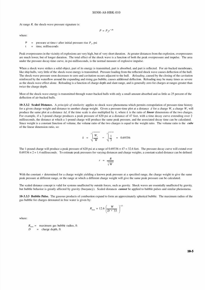
8132019 Articol despre explozii submarine
httpslidepdfcomreaderfullarticol-despre-explozii-submarine 624
S0300-A8-HBK-010
The expanding bubble radiates a pressure
Figure 10-4 Gas Bubble Expansion
WATER SURFACE
EXPLOSIVECHARGEIN WATER
ON DETONATIONGASES EXPAND
TO FORM ANAPPROXIMATELY
SPHERICAL BUBBLE
BUBBLE COLLAPESFROM REGION OF
GREATEST PRESSURE(ARROW LENGTHSINDICATE WATER
VELOCITY)
BUBBLE EXPANDSPRINCIPALLY INONE DIRECTION
(a) (b) (c) (d)
Figure 10-5 Pressure-Time Signature 60 Feet from 300-PoundTNT Charge Detonated in Deep Water
SHOCK WAVE
FIRSTBUBBLEPULSE
1770 LBIN2
80 LBIN2Po
O SEC O69 SECTIME
APPROX 100 microSEC
P R E S S U R E
pulse that is less intense than the initial
shock wave but is still significant The
expanding gases cause a rapid outflow of
water that continues temporarily after the
gas pressure and water pressure equalize
because of the waterrsquos momentum The
continued expansion causes pressure in thebubble to drop below ambient hydrostatic
pressure The inward pressure differential
soon causes a reverse flow and the bubble
is recompressed The bubble collapses
away from the region of greatest pressure
as shown in Figure 10-4 The momentum
of the moving water compresses the bubble
beyond equilibriummdashthe bubble will
expand again creating a second weaker
bubble pulse The cyclic expansion and
contraction of the gas bubble with
attendant pressure pulses continues through
several oscillations or until the bubble vents
at the surface Usually only the first pulseis significant At the end of the first bubble
contraction 84 percent of the energy
released by the explosion has been
transmitted to the surrounding water By
the end of the second contraction the
bubble has lost 92 percent of the original
energy Water depth and the proximity of
boundary surfaces influence the form and
movement of the bubble Buoyancy causes
the bubble to rise but hydrodynamic forces
drive it toward rigid surfaces and away
from the water surface The time required
for the expansion-contraction cycle varies
with charge weight and explosive typeranging from 002 to 07 seconds Bubble
pulses are likely for detonations at depths
greater than 25 feet For small charges
(less than 2 frasl 3-pound) two bubble pulses
have been observed for charges in as little as
four feet of water
Peak pressure from the first bubble pulse is less than 20 percent of that of the shock wave but duration is much greater areas under the two
pressure-time curves are comparable Figure 10-5 shows pressure-time signature at a distance of 60 feet from a 300-pound TNT charge fired
50 feet below the surface in deep water The bubble pulse strikes after the initial shock wave and may cause reloading and additional damage
Bubble pulse reloading is somewhat mitigated when charges are detonated alongside a hull The effects can be further mitigated by selecting
a charge weight that produces a maximum bubble radius significantly less than the minimum distance between the charge and the hull The
maximum charge weight for a given bubble radius is found by solving the bubble radius formula for charge weight
W = R 3
126 D 33
where
W = charge weight lbs TNT to create a bubble of radius R ft
D = charge depth ft
10-610-6
8132019 Articol despre explozii submarine
httpslidepdfcomreaderfullarticol-despre-explozii-submarine 724
S0300-A8-HBK-010
Gas bubbles from charges under or near a
Figure 10-6 Seafloor Geometry Likely to Focus Explosive Energy
CHARGE HARDBOTTOM
ship may collapse adjacent to the hull platingas they rise Pressure pulses from bubblescollapsing near the hull may cause damagemore severe than the initial shock wave andreloading If the bubble rises to a positionvery close to the hull it may collapse andimpact the hull with a water hammer Thesebubble effects are of special concern becausehydrodynamic forces cause bubbles tomigrate toward hard surfaces
For charges on the seafloor or in shallowwater the pressure wave and energy trans-mitted through the water may increase overthe free water values The increase de-pends on the rigidity of the seafloor Veryhard seafloors reflect a large percentage of the energy of incident shock wavesmdashtheenergy available for damage may beincreased 50 percent Very irregularseafloors can focus the shock waves causing very high local overpressures Figure 10-6 shows a geometry where shock-wave focusing is likely
In addition to hull damage the sudden velocity imparted to the hull by the shock wave may cause shock damage to machinery electronics another shipboard equipment Equipment may be exposed to accelerations of several hundred to a thousand gravities (grsquos) even when hull damag
is not serious Shock load intensity is indicated by a shock factor defined in Paragraph 10-341
10-34 Blast Effects of Underwater Explosions Effects on structures personnel and marine life depend on peak overpressure and impulseOverpressure and impulse at a distance from the blast have been related to charge weight distance from the charge water depth depth to thecharge and depth to the target Empirical relations based on charge weight and other factors predict blast effects
Blast effects can be estimated with fair accuracy in deep water where pressure waves reflected from the bottom do not affect pressure levelsignificantly In shallow water bottom-reflected waves alter blast effects in an unpredictable manner because of variations in seaflootopography Ridges and other features can cause shadow zones of low overpressures Reflection from hard seafloors or hard strata under thisoft layers will generally increase overpressures and can focus shock waves to produce exceptionally high local pressures Hard dense materialreflect shock waves and transmit ground vibrations more efficiently than soft seafloors These effects are not readily quantified and must bestimated subjectively
10-341 Structural Effects The hull damage to a ship is a function of an empirically derived damage factor defined as the square root of W Rthe damage factor where W is the charge weight (in equivalent pounds of TNT) divided by the slant rangemdashthe straight line distance betweethe hull and the charge Figure 10-7 (Page 10-8) shows curves of the damage factor ( radicWR) as a function of the charge depth to range ratio ( D R
for three nominal hull thicknesses and two categories of damage Light damage is
1
frasl 2
-inch to 1-inch deflection between stiffeners little if anbuckling of stiffeners and no damage to main bulkheads (ie damage that would not require repair) Moderate damage is 1-inch to 2-incpermanent deflection between stiffeners with minor buckling of stiffeners and bulkheads To find charge weight the appropriate curves are enterewith the charge depth to range ratio D R to find the square root of W R corresponding to the hull thickness The equivalent TNT charge weighW can then be found The curves are generally applicable only for charge weights greater than 10 pounds at distances greater than 10 feet fromthe ship If a charge weight of less than 10 pounds or the slant range is less than 10 feet the small charge formula below applies
For small charges detonated at close range the charge weight that will rupture curved stiffened plating is an empirical function of range materiastrength plating thickness and stiffener spacing
W =
(68 times 106)(σt 3 )
1 -
2 R
l
1 + 2 Rl
2
where
W = charge weight to initiate rupture lbs of TNTσ = plating yield strength psit = plating thickness in
R = slant range center of charge to outer plating surface inl = stiffener spacing in
The small charge formula was developed from tests on submarine hull mockups in deep water it should be applicable to any stiffened platstructure but there is no supporting data
10-10-
8132019 Articol despre explozii submarine
httpslidepdfcomreaderfullarticol-despre-explozii-submarine 824
S0300-A8-HBK-010
The shiprsquos critical machinery and cargo
Figure 10-7 Damage Factors
DR
DR
(b) MODERATE DAMAGE
(a) LIGHT DAMAGE
34 PLATE
34 PLATE
12 PLATE
12 PLATE
14 PLATE
14 PLATE
0
0
01
01
02
02
03
03
W
W
R
R
04
04
05
05
06
05
05
06
06
07
07
08
08
09
09
10
10
11
11
12
12
= CHANGE WEIGHT lbs TNT
= SLANT RANGE
= CHARGE DEPTH
= DAMAGE FACTOR
w
R
D
WR
near the detonation area may be damagedby shock-induced motions For chargesless than 20 pounds only small hull-mounted equipment in the immediate areaof the detonation is likely to suffer damageThe degree of shock damage to be expectedis estimated from the shock factor Theshock factor at the point on the hull nearestthe charge is computed from
where
Shock Factor(SF) = W
R
1 + sinφ2
R = slant range ftW = equivalent TNT charge
weight lbs = charge weight times RE factor
φ = angle between the shortestline from the hull to thecharge and a tangent to the
hull at the point nearest tothe hull as shown in Figure10-8
To determine the allowable charge weightan appropriate shock factor is selected fromTable 10-1 to solve for W
10-342 Linear Charges Linear
W = 4(SF)2 R 2
(1 + sinφ)2
demolition charges are frequently used insalvage Line charges produce a complexpressure field In a horizontal plane arounda freely suspended straight line chargemaximum peak pressures occur about 120degrees from the detonation end of thecharge Pressure decay time is about thesame for a given range regardless of orientation relative to the charge axisPressure-time histories on a vertical planeperpendicular to the line charge are quitesimilar to those for a compact charge of same weight with slightly higher peak pressures (2000 psi at 35 feet from acompact 50 pound charge as opposed to2400 psi at 35 feet from a 25 foot linearcharge with 50 pounds of explosive) Table
Table 10-1 Degree of Damage for Various Shock Factors
Shock Factor Damage
lt01 Insignificant ndash nuisance damage only l ight bulbs fuses etc
01 - 015 Tube relay fuse and light bulb failures general electronic failures piping leaks
and possibly a pipe rupture
015 - 020 Increase in above damage piping ruptures likely machinery misalignments likely
020 General machinery damage
10-2 shows the horizontal distribution of peak pressure at distance of 20 feet from
the midlength of a Navy Mk 8 Mod 2 hosecharge (25-foot rubber hose filled with 50pounds of a 7030 mixture of compositionA-3 and aluminum powder) detonated whilefreely suspended 10 feet below the watersurface in approximately 40 feet of water
10-810-8
8132019 Articol despre explozii submarine
httpslidepdfcomreaderfullarticol-despre-explozii-submarine 924
S0300-A8-HBK-010
In An Exploratory Investigation of the
Figure 10-8 Geometry for Calculating Shock Factor
CHARGE
R
φ
Effects of Underwater Line Charges onShip Plating Naval Ship Research andDevelopment Center December 1967 JKFleming and RE Oliver report that thedeflection of hull plating between stiffenerscaused by Navy Mk 8 Mod 2 hose chargescan predicted approximately by
where R t W and σ are as previously
d = 37 a
Ro σ t
2WLRo
4 R2
o L 2
defined and
d = plating set deflection in L = charge length fta = e ff ec ti ve p la ti ng s iz e
(between stiffeners) in
Table 10-2 Pressure Distribution Around Mk 8 Mod 2 Hose Charge
Gage position (angle between line from gage to midlength
and charge axis with detonation end at 0 degrees)
Peak Pressure
psi20 1300
30 1500
40 1730
50 2100
60 2600
70 3300
80 3730
90 3900
100 4220
110 4620
120 5000
130 4000
140 3960
150 2390
160 2250
170 2400
180 3050
All pressures measured 20 feet from midlength of charge
For rectangular plates effective plating sizeis determined from
where
a = 116
90
1
x 2
1
y 2
x = plate width in y = plate length in
10-343 Multiple Charges Multiplecharges detonated simultaneously aretreated as a single large chargemdashthe totalweight of all charges in the array must beless than the maximum acceptable chargeweight determined as described inParagraph 10-341 for a single charge
For multiple charges detonated individuallywith delays between detonations themaximum acceptable single charge weightis determined Charge weights should be
Figure 10-9 Minimum Delay Between Detonations in Charge Array
CHARGE DEPTH FEET
55 LBS TNT
35 LBS TNT
20 LBS TNT
10 LBS TNT
5 LBS TNT D E
L A Y
T I M E
S
E C O N D S
0
05
10
15
20
25
30
10 20 30 40 50 60
one-third the single charge weight or less toprevent progressive hull damage Aminimum delay time between detonations isnecessary to allow the energy from theprevious detonation to dissipate so structureblast loading is not cumulative Minimumdelay times are taken from Figure 10-9
10-344 Ballasting Water-backed hullsare more resistant to shock damage thanair-backed hulls When internal waterdamage is not a problem and the ship can
contain the water spaces in the vicinity of explosive charges may be ballasted How-ever the first air-backed bulkhead exposedto the explosive loading can incur damageif it is in close proximity to the charge
It is not necessary to flood exactly to thewaterline to increase shock resistance butthere should be several feet of water in anyballasted space and six inches to one foot of air between the water surface and the nextdeck No reliable data are available forpredicting how much the charge weight maybe increased if the ship is ballasted A large bubble collapsing near the hull can cause considerable damage even to water-backed plating
10-10-
8132019 Articol despre explozii submarine
httpslidepdfcomreaderfullarticol-despre-explozii-submarine 1024
S0300-A8-HBK-010
10-35 Effects on Marine Life Environmental protection agencies may require salvors to estimate blast effects on local marine life Lethal
ranges may be specified that will limit charge weight
Lethal range seldom exceeds 650 feet and is estimated by
Table 10-3 Fish Kill Range Constants
Fish Weight Depth of Blast ft K
α
1 oz 10 328 0220
1 oz 50 385 0256
1 oz 200 475 0262
1 lb 10 174 0264
1 lb 50 235 0275
1 lb 200 272 0299
30 lbs 10 86 0284
30 lbs 50 131 0314
30 lbs 200 139 0342
H MAX = KW α
where
H MAX = maximum horizontal range of lethal overpressures
feet
K α = coefficients from Table 10-3
W = charge weight pounds
Although fish kill range can be estimated it is very difficult to keep
fish out of a specified area Bubble screens have been used with
some success
10-36 Safe Distances for Above-water Blasts The minimum
distances to protect personnel against shock wave and overpressure
are
SD = 300 W 13
Bare charges on or in ground
SD = 350 W 13
Charges in rock
where
SD = safe distance ft
W = charge weight lbs TNT = W times RE factor
Fragments and debris may be thrown greater distances and hazard personnel in the open The projectile hazard can be reduced by
bull Greater separation distances
bull Confinement of the explosion at the source
bull Barricades between personnel and the blast site
bull Evacuation of nonessential personnel
bull Overhead cover
10-1010-10
8132019 Articol despre explozii submarine
httpslidepdfcomreaderfullarticol-despre-explozii-submarine 1124
8132019 Articol despre explozii submarine
httpslidepdfcomreaderfullarticol-despre-explozii-submarine 1224
S0300-A8-HBK-010
10-41 Charge Weight Charge weight selection is based on two criteria
bull The charge must be large enough to perform the task
bull The charge must not be so large that it causes unacceptable damage to the casualty nearby structures or the environment
The minimum charge weight that will accomplish the task (in one shot) may be greater than the maximum charge weight what will not causedamage It is usually possible to perform the task in a series of steps each using charge weights smaller than the maximum acceptable weight
10-42 Underwater Blasting Water
Figure 10-11 Shared Charge Cutting Sequence
EXPLOSIVECHARGE
CONTAINER
LINER
CAVITY
SHAPEDCHARGE
(a)
S T A N D
- O F F
DETONA-TION WAVEAPPROACHESCAVITY LINER
(b)SHOCK WAVECOLLAPSESLINER INDUCINGJET FORMATION
(c)
CUTTING JETAPPROACHESTARGETSURFACE
(d) PLASTIC FLOW
IS INDUCED INTHE TARGETMATERIAL ANDTHE JET STARTSTO PENETRATE
(e)
JET PASSESTHROUGHTHE TARGET -CUT ISCOMPLETE
(f)
INITIATORpressure on the side of an object oppositethe explosive blast opposes the impact andexpansion of the explosive When the work involves moving large surface areasresistance to movement caused by waterpressure and hydrodynamic drag issignificant and explosive effectiveness isreduced For example it takes about onepound of explosive to break up and move acubic yard of rock in dry air Two to sixpounds of explosive per cubic yard arerequired to break and move the same rock underwater Explosive effectiveness is
further reduced as depth increases
Steel cutting by ribbon charges shapedcharges etc where little surface movementis required is not significantly affected byimmersion in water Shaped chargeeffectiveness is reduced if water cannot bedisplaced or evacuated from the cavity andstand-off (shaped charges are discussed inParagraph 10-421)
Most explosives detonate satisfactorilyunder water Some explosives containwater-soluble ingredients and aredesensitized with time when immersedunless sealed in waterproof containers
Certain explosives depend on dispersed microscopic air or gas bubbles for ease of initiation Immersion in deep water compresses the bubblesand renders them ineffective so they can be used only in shallow water or if specially formulated for deep water use Explosives dependingon dispersed bubbles for initiation include those based on or sensitized by nitroglycerine and nitroglycerol such as gelignites and blastinggelatins and those containing aqueous solutions of ammonium nitrate such as water gels and emulsions
Most military high explosives and commercial explosives based on PETN RDX and TNT can be used reliably in deep water because theyare not are not significantly water-soluble and do not depend on gas bubbles for initiation
Overlying water is an effective tamping agent but if the charge is not in intimate contact with the target the intervening water layer will largelynegate the tamping effect Even a thin water layer between the charge and target will dissipate some of the explosive energy before it reachesthe target The shock and compression waves pass through two media interfacesmdashexplosive to water and water to target energy is reflectedaway from the target at each interface If charges cannot be placed in intimate contact with the work additional tamping in the form of sandbags clay or soil should be used to overcome the dissipation of energy by the intervening water
Potential water tamping lends a slight theoretical advantage to blasting from the wet side of a hull but offsetting advantages accrue whenexplosives are placed in the dry
bull Explosives fuses and initiators are not subject to the desensitizing effects of water immersion or to disturbing forces of currentand surge
bull Charges can be placed more effectivelymdashit is easier to secure charges and intimate contact with the target surface can be attained
bull Charges and firing circuits can be inspected immediately before firing
bull There is greater control over the personnel placing explosives and their work can be monitored and inspected with less effort
Immersion time prior to firing should be minimized to reduce the desensitization of the explosives and the possibility that current or surge willdislodge charges or initiating circuits
10-1210-12
8132019 Articol despre explozii submarine
httpslidepdfcomreaderfullarticol-despre-explozii-submarine 1324
S0300-A8-HBK-010
10-43 Cutting and Fracturing Charges A principal use of explosives in salvage is cutting hull plating and structure in ships High-velocitybrisant explosives such as TNT and plastic explosives are best for cutting steel or aluminum Structural members are cut by a variety ocharges
bull Shaped charges ndash A lined or unlined cavity in the explosive produces a high-energy cutting jet
bull Fracturing charges ndash Specialized charge geometry causes convergence of strain waves in the target
bull Simple contact charges ndash Breakage is accomplished by the combined but uncoordinated effects of shock waves strain pulses angas expansion
Shaped and fracturing charges are far more efficient than contact charges and should be used when available and when suited to working conditions Because of their relatively small charge weights shaped and fracturing charges must be placed precisely and must be held in positioagainst current or surge to be effective If charges cannot be placed precisely better results may be obtained with less efficient contact charge
10-431 Shaped Charges A hollowed-
Figure 10-12 Typical Shaped Charges for Salvage Work
FLEXIBLE LINEARSHAPED CHARGE
BOX TYPELINEAR CHARGE
EXPLOSIVE
TARGET
CASE
METALLINER
ENCLOSED
STAND-OFFSPACE
CYLINDRICALCHARGE
EXPLOSIVECORE
DENSEFLEXIBLE
SHEATH
WOODENSPOOL
out or shaped charge detonated against ahard surface produces a crater that isapproximately a mirror image of the chargecavity The shaped charge is initiated at apoint behind the cavity the detonation waveexpands omnidirectionally from theinitiation point or axis Reaching the cavitythe detonation wave converges on a plane
(for linear charges) or axis (in cylindricalcharges) perpendicular to the target surfaceThe convergence of the shock waveconcentrates the explosive energy in a smallarea The resultant cratering is called the
Munro Effect If the charge is lined withmetal or other dense material the explosioncollapses the liner and carries it in the shock wave to the target surface as a slug (orblade) of metal and hot gas that acts as acutting jet The jet heats and erodes thetarget surface Shock-wave pressure and jeteffects combine to induce plastic flow in thetarget and cut through the material Figure10-11 illustrates the cutting sequence for alined shaped charge
For optimum effect shaped charges arepositioned at a stand-off distance from thetarget surface to allow the penetration jet toform completely before it reaches the targetsurface Optimum stand-off varies with thecavity angle and charge size stand-off isd et er m in ed f r om t ec hn ic al o rmanufacturerrsquos data for the charge used
Various-sized cylindrical shaped chargesare made for hole cutting Linear chargesare used for long cuts Linear charges areusually made in the form of a box with thecavity liner set across the inside of the boxas shown in Figure 10-12 Flexible linearshaped charges can conform to irregular
surfaces and cut lines Well-designedlinear cutting charges obtain good resultswith relatively small charge weightsIndividual charge weight and explosiversquosconsumption are based on data publishedfor the particular explosives used Data formilitary shaped charges is given in the Technical Manual for the Use of Explosives in Underwater Salvage (NAVSEA SW061-AA-MMA-010Typical manufacturerrsquos data for linear shaped charges are shown in Figure 10-13 (Page 10-14)
10-110-1
8132019 Articol despre explozii submarine
httpslidepdfcomreaderfullarticol-despre-explozii-submarine 1424
S0300-A8-HBK-010
Shaped charges can be improvised as
Figure 10-13 Typical Manufacturerrsquos Data for Linear Shaped Charges
STAND-OFF FOR OPTIMUM PERFORMANCE(RDX OR PETN EXPLOSIVE)
MINIMUM CUTTING PERFORMANCEAT OPTIMUM STAND-OFF
MINIMUM CUTTING PERFORMANCEAT OPTIMUM STAND-OFF
MINIMUM CUTTING PERFORMANCEAT OPTIMUM STAND-OFF
MINIMUM CUTTING PERFORMANCEAT OPTIMUM STAND-OFF
5
30 15
10
05
02
01
2010
JETCORDSTAND-OFFTARGET
05
02
01
05
0201
01
02
05
01
02
01
02
05
10
20
02
05
01
02
05
10
1 0
2 0
3 0
4 0
5 0
1 0 0
2 0 0
EXPLOSIVE CORELOAD GRAINSFOOT
EXPLOSIVE CORELOAD GRAINSFOOT
EXPLOSIVE CORELOAD GRAINSFOOT
EXPLOSIVE CORELOAD GRAINSFOOT
NOTE CUTS AT 7 AND 10 GRFTMADE AT ZERO STAND-OFF
EXPLOSIVE CORELOAD GRAINSFOOT
100
5
5
10
10
50 100 200 500 1000
20
20
50
50
100
100
200 500
200 500 1000 2000 5 0 0
S T A N D
- O F F I N C H E S
T H I C K
N E S S
C U T
I N
C H E S
T H I C K N E S S
C U T
I N
C H E S
T H I C K N E S S
C U T
I N
C H E S
T H I C K N E S S
C U T
I N
C H E S
1 0 0 0
2 0 0 0
A L U M
I N U M
S H E A
T H
C O P P
E R S H E A
T H
L E A D
S H E A
T H
C 1 0 1 8 S T E E
L T A R G
E T
COPPER-SHEATHEDJETCORD (RDX ORPETN EXPLOSIVE)
LEAD-SHEATHEDJETCORD (RDX ORPETN EXPLOSIVE)
2024-T351ALUMINUM
TARGET
C10118STEELTARGET
2024-T351ALUMINUM
TARGET
C10118STEELTARGET
ALUMINUM-SHEATHEDJETCORD (RDX
OR PETN EXPLOSIVE)
SILVER-SHEATHEDJETCORD
(DIPAMEXPLOSIVE)
CUT7075-T6
ALUMINUMTARGET
OPTIMUMSTAND-OFF
shown in Figure 10-14 When performance
data for a particular material is not
available cutting ability can be estimated
from the following
where
t = t o
ρρ
o
t = unknown cutting capacity
(thickness) in material of
density ρt o = known cutting capacity in
material of density ρo from
manufacturerrsquos data
Water in the stand-off and cavity prevents
the formation of the cutting jet Theenclosed stand-off of box-type shaped
charges excludes water but boxes can
withstand hydrostatic pressures only to
shallow depths that vary with the particular
unit For depths of 30 to 60 feet the stand-
off can be filled with closed-cell plastic
foam The foam inhibits jet formation
slightly so that performance is decreased
For deeper immersion the stand-off and
cavity must be constructed to withstand
hydrostatic pressure or made free flooding
and then evacuated with compressed air or
gas at depth For underwater use flexible
linear charges can be enclosed in flexibletubes filled with foam or evacuated by
compressed gas One manufacturer markets
a line of circular cutters prefabricated with
compressed gas fittings
10-432 Fracturing Charges A diamond-shaped sheet of plastic explosive laid on a steel plate and detonated simultaneously from two
opposite corners will fracture the metal along a line between the two uninitiated corners This effect is shown in Figure 10-15(a) The fracture
mechanism depends on the pressure rise as the shock waves from the two detonating points collide followed by the relaxation as the waves
pass through one another and the combined effect of two tension waves rebounding from the far side of the target This arrangement is a
diamond charge and is suitable for cutting bars and pipes but has limited application for plate cutting because the fracture extends only slightly
beyond the charge
The diamond charge principle was first applied to extended plate cutting in fracture tape Fracture tape shown in Figure 10-15(b) consists of
a series of diamond charges connected by continuous strips of explosive along the edges of the charges Fracture tape has seen only limiteduse because it was not manufactured in a flexible form The charge may fail to cut if bilateral asymmetry develops between the two initiation
trains Fracture tape can be improvised by cutting explosive sheet to the appropriate shape
Shock-wave refraction tape (SRT) is a recently developed explosive charge that works on the principle of shock-wave collision within metal
targets In this charge a continuous strip of explosive is molded to the back of an inert wave-shaping element as shown in Figure 10-15(c)
One manufacturer uses magnetic rubber as the wave-shaping element providing both flexibility as well as an attachment method (provided the
surfaces are clean and smooth) The performance of shock-wave refraction tape is comparable to that of shaped charges when cutting ordinary
steels very high strength fracture-resistant steels may not be cut as easily There is no cavity or stand-off to flood so SRT is more adaptable
to underwater use than linear shaped charges
10-1410-14
8132019 Articol despre explozii submarine
httpslidepdfcomreaderfullarticol-despre-explozii-submarine 1524
S0300-A8-HBK-010
Figure 10-14 Improvised Shaped Charges
SHEETEXPLOSIVE
STEEL ORALUMINUM
ANGLE
PLASTICEXPLOSIVE
PLASTICEXPLOSIVE
CONE
WINEBOTTLE
STICKS TAPEDTO SIDE ASSTAND-OFF
FUSE
CAP
S T A N D - O
F F
D I S T A N C E
FOOD CANWITH BOTHENDS CUT
OUTPLASTICEXPLOSIVE
SHEETMETALOR LEADSHEETCONE
RIVET
SIDES OFCAN FORMSTAND-OFF
CAP
80˚ - 90˚
Figure 10-15 Fracturing Charges
A
Arsquo
A ArsquoEXPLOSIVE
FRACTURE
EXPLOSIVESHOCK-WAVEFRONTS
REFLECTEDTENSION WAVE
(a) DIAMOND CHARGE (INITIATED AT POINTS A AND Arsquo)
(c) SHOCK-WAVE REFRACTION TAPE (SRT)(b) FRACTURE TAPE
EXPLOSIVE
INERT BARRIERSINITIATION POINT
EXPLOSIVE
WAVE-SHAPINGELEMENT
FRACTURES TENSIONWAVE
SHOCK WAVE
10-110-1
8132019 Articol despre explozii submarine
httpslidepdfcomreaderfullarticol-despre-explozii-submarine 1624
S0300-A8-HBK-010
10-433 Contact Charges Simple
Figure 10-16 Steel Cutting Contact Charges
DETONATINGCORD
EXPLOSIVE
STEEL PLATE
WELDS
STEELCHANNEL
STUD
PLATE
SECURINGSTRAP
EXPLOSIVESHEET OR
PLASTICEXPLOSIVE
contact charges require much heaviercharges than shaped or fracturing chargesExplosive performance can be increasedand charge weight reduced by carefulcharge placement confinement tampingand by scoring cut lines with cuttingtorches or mechanical cutters Some
effective charge placements and geometryare shown in Figure 10-16
Charge weights can be estimated from thefollowing relationships
where
W = 3
8 A Structural steel
W = D 2 High carbon or alloy steel
W = charge weight lbs TNT
A = cross-sectional area of sectionto be cut in2
D = diameter or thickness of section to be cut in
To determine charge weights for explosivesother than TNT the TNT charge weight isdivided by the relative effectiveness (RE)factor
10-434 Charge Placement Cutting charges are most effective when the cut line is adjacent to but not on a rigid portion of the target surfaceThe target must be restrained from moving away from shaped and fracturing charges so the explosive energy is expended in cutting or fracturingthe target rather than pushing it away Contact charges create a strong shearing action along the line between the movable and rigid surfaceHull cutting charges are most effective when slightly offset from frames
bull If placed in the middle of the span a large portion of the explosive energy is expended in deflecting the plate
bull If placed directly over a stiffener both the stiffener and the plate must be cut
For efficient cutting charges must be placed in intimate contact with the target surface Charges must be secured to all vertical steeply angledand overhead surfaces and to horizontal surfaces where current wind vibration or target movement may dislodge them Where no tie-downpoints exist the following securing methods can be used
bull Light metal straps bolted to studs explosively set or friction welded along each side of the cut line
bull Tie-down wires lines or bongee cords inserted through holes cut drilled or burned through the plating (tie-downs can also beled to studs or magnetic clamps)
bull Sandbags or similar weights placed on charges on horizontal surfaces
bull Backing charges with magnetic strips adhesive strips or small suction pads (these methods have had limited success)
bull Hose charges can be stretched between tie-down points over flat or smoothly convex surfaces
10-435 Ship Sectioning Explosives are commonly used to section wrecks for piecemeal removal or to separate a casualty into two piecesso that one part can be salvaged Ship sectioning including explosive methods is discussed in the US Navy Ship Salvage Manual Volume 2(S0300-A6-MAN-020) The following notes supplement that discussion
10-1610-16
8132019 Articol despre explozii submarine
httpslidepdfcomreaderfullarticol-despre-explozii-submarine 1724
S0300-A8-HBK-010
When cutting a ship transversely the internal structure must be cut as well as the more accessible hull plate and stiffeners It is very difficu
to obtain complete separation in a single shot Salvors should plan to make cuts in several shots or have thermal or mechanical cutting gea
available to sever stubborn structure
In a landmark operation in 1973 the salvageable aft section of a 960-foot laden ore carrier was explosively separated from the forward part o
the ship which was abandoned The ship had sunk by the bow in 130 feet of water With holds 7 8 9 and 10 their associated wing and
double-bottom tanks and the machinery spaces dry the after section was buoyant and afloat The hull was cut in way of number 7 hold b
more than 1800 feet of custom engineered and fabricated high speed explosive cutters All cutters were placed in the dry number 7 wing anbottom tanks Instantaneous separation (necessary to prevent capsize of or damage to the aft section) was attained by
bull Placing cutters against all bulkheads shell plating stringers void tank sections and pipes extending through the transvers
bulkhead separating holds 7 and 8
bull Taking advantage of the vertical shear on the hull resulting from the weight of the forward section laden with 90000 tons of ore
and the buoyancy of the after section and
bull Maintaining a 300-ton horizontal astern pull on the after section as the cutters were detonated
Blast curtains were rigged in the number 7 tanks and hold and the number 8 wing and bottom tanks were pressurized with compressed air to
protect the separating bulkhead A diverrsquos survey after the successful separation revealed no damage to the bulkhead The operation was mad
possible by the salvorsrsquo employment of specialist explosives engineers who custom designed the explosive cutters taking into account permissiblblast effects on the aft number 7 bulkhead gas generation and dispersion requirements mutual interference between charges and the strength
of hull structural members See The Cutting of the Igara in Reedrsquos Commercial Salvage Practice for a more detailed discussion of th
operation
The order in which the different members are to be cutmdashas well as the methods to be usedmdashmust be considered carefully Preliminary cut
should not weaken the structure to the point that it is in danger of collapsing and injuring personnel placing charges for subsequent cuts
Cutting methods are frequently combined A hull can be opened up with explosives to permit access to internal structure to be cut by mechanica
or thermal methods In some cases preparatory weakening cuts are made by divers with oxy-arc or exothermic torches with the final cuts mad
explosively
Simple types of ships are better candidates for explosive sectioning than more complex types The following ship types lend themselves t
explosive sectioning
bull Transversely framed ships because there are fewer longitudinal stiffeners to cut
bull Freighters and bulk carriers because most do not have centerline longitudinal bulkheads (some bulk carriers have wing tanks whos
inner bulkheads must be cut) Small ships often do not have double bottoms
bull Small single-product tankers because they do not have wing tanks or double bottoms
The following ship types are not good candidates for explosive sectioning
bull Longitudinally framed ships because of the large number of longitudinal stiffeners
bull Passenger ships and warships because of their extensive joiner work internal subdivision wireways piping and ventilatio
systems
bull Large tankers and product carriers because they are constructed with two or more longitudinal bulkheads
bull Freighters with insulated holds
10-110-1
8132019 Articol despre explozii submarine
httpslidepdfcomreaderfullarticol-despre-explozii-submarine 1824
S0300-A8-HBK-010
10-44 Seafloor Blasting Seafloor
Figure 10-17 Obstruction Blasting
CONTACT BLASTING MUDCAPPING
SNAKEHOLING
STEMMINGSTEMMING
CHARGE
CHARGE
BLOCKHOLING
blasting moves large amounts of seafloor
material by channeling trenching etc or
removes isolated obstructions such as
pinnacles coral heads and boulders The
basic techniques are
bull Contact Blasting ndash Chargesare placed on the formation
to be blasted either indi-
vidually or in line or
checkerboard patterns The
detonating explosive imparts
a violent blow to the seafloor
material The efficiency of
contact blasting depends on
maintaining intimate contact
with the material to be
blasted Contact blasting is
the least efficient blasting
method in terms of explosive
consumption but requires the
least time and effort to
prepare and set charges
bull Boreholes ndash Internal charges
are placed in boreholes
drilled or augured into the
object or strata to be blasted
10-441 Rock Blasting The choice of explosive for a particular rock-blasting job depends on the hardness and density of the rock and the
type of breakage desired Fast brisant explosives such as TNT or composition C-4 are required to break most kinds of rock although slower
explosives are effective on soft rock such as limestone
Rock is weakest in tension so internal charges are most effective Contact blasting depends on the tamping effect of overlying water to confine
the explosion momentarily and is effective only on soft rock and coral where the material is broken by crushing rather than shattering The
rock fragments are moved by the expanding gases so high gas production is required to move dense rock If the object is to break up rock for
removal by nonexplosive means gas production of the explosive is less important Individual boulders are broken by one of the methods
discussed below The methods are illustrated in Figure 10-17
bull Mudcapping ndash A contact charge is covered with 10 to 12 inches of mud clay or moist soil tamping Plastic clay is the most
effective tamping Loose sand should not be used but sandbags are effective
bull Snakeholing ndash The charge is placed in a hole jetted bored or otherwise excavated under an object lying on or partially buried
in a soft seafloor Snakeholing is more effective than mudcapping under all conditions and requires about one-half as much
explosive as contact blasting
bull Blockholing ndash The charge or charges are placed in one or more boreholes Explosive effect can be altered by changing charge
weights and placement rock formations boulders concrete structures etc can be completely demolished be broken into
fragments of varying size or have portions broken off Blockholing requires about one-third as much explosive as contact blasting
Table 10-4 gives approximate explosive requirements in pounds per
Table 10-4 Powder Factors (lbyd3) for Rock Blasting
Blas ting Metho d A ir B la sting Und erwater Blas ting
Contact Blasting Not effective 6 - 20
Mudcapping 1 - 2 4 - 15
Snakeholing 1 - 11 frasl 2 3 - 10
cubic yard or powder factor for different rock-blasting methods A
range of powder factors for each method is given The actual powder
factor for any project will depend on
bull The relative density and toughness of the rock
bull Whether individual boulders or massive rock formations
are being blasted
bull Water depth
10-1810-18
8132019 Articol despre explozii submarine
httpslidepdfcomreaderfullarticol-despre-explozii-submarine 1924
S0300-A8-HBK-010
The lower values in Table 10-4 are based
Table 10-5 Rock Density and Toughness
Type of Rock Density lbft3 Relative Toughness (Limestone = 1)
Andesite 150 - 175 11
Basalt 150 - 200 17 - 23
Conglomerate 125 - 162 NA
Dioritic 156 - 200 19 - 21
Felsite 150 - 200 NA
Gabbro 169 - 200 NA
Granite 156 - 194 15 - 21
Gneiss 150 - 181 10 - 19
Limestone 160 - 187 10
Marble 131 - 181 NA
Quartzite 125 - 200 19 - 27
Sandstone 124 - 194 15 - 26
Schist 150 - 175 10 - 21
Shale 112 - 194 NA
Slate 156 - 194 12
on blasting massive limestone at depths of 30 to 60 feet Values high in the range areused with tougher or denser rocks andgreater depth Lower values are used whenblasting individual boulders or outcrop-pings Table 10-5 compares densities andtoughness of common rocks
Rock blasting by internal charges is mosteffective when there is a free face approxi-mately parallel to the borehole Thedetonation of the explosive creates a highgas pressure in the charge hole generating acompressive strain pulse in the surroundingrock The compressive pulse travels outwardin all directions Near the hole theamplitude of the strain pulse is sufficient tocrush the rock Amplitude decays rapidly asthe pulse travels outward until it can nolonger crush the rock The pulse travels out-ward until it is reflected from a free surfaceas a tensile strain pulse As rock is much
Figure 10-18 Excavation Rock Blasting
DRILLING FACE
WORKING OR FREE FACE
BOREHOLE
BENCH
EXCAVATION FLOOR(PROJECT DEPTH)
L
B
BltL
INSUFFICIENT EXPLOSIVEENERGY RELEASE AT
BOTTOM OF HOLE
B
MAINFRACTURELINES
COLUMN LOADEDHOLE
45˚
STRESS PATTERN FOR ACONCENTRATED CHARGE
IN BOTTOM OF HOLE
REFLECTEDTENSION WAVE
UNREFLECTEDCOMPRESSIONWAVE
TOE
weaker in tension than compression the
tensile pulse is able to break the rock pro-gressing from the free face back towards thecharge hole The expanding gases in thecharge hole are not directly responsible formuch of the rock breakage to some extentthe rock is pulled apart rather than pushedapart
Blasting massive seafloor rock formations issubject to constraints similar to those en-countered in quarry blasting and similarmethods are employed Detailed informationon rock blasting is found in publications onmining and quarrying For effective blastingit is necessary to establish a breaking orworking face at an angle to the drilling faceThe drilling face is most often the horizontalseafloor the working face is vertical orinclined from the vertical by an angle of 45degrees or less The working face is brokenback in steps by detonating charges in rowsof holes behind the face For cuts deeperthan the maximum practical drilling depththe working face is broken back in stages byestablishing intermediate floor levels orbenches as shown in Figure 10-18
A working face can be established in aflush surface by blasting out a crater with asingle charged hole cluster of holes or lineof holes Empty relief holes between andaround charged holes provide free faces toreflect strain pulses and space for displaced
rock to move into The excavation floorand work face can be squared up bysubsequent blasting
Boreholes can be drilled by diver-operated jackhammers or rock drills for smalloperations For extensive drillingoperations a spud-moored drill barge or asubmersible crawler-mounted rock drillshould be used
10-110-1
8132019 Articol despre explozii submarine
httpslidepdfcomreaderfullarticol-despre-explozii-submarine 2024
S0300-A8-HBK-010
10-442 Coral Blasting Coral is difficult
Figure 10-19 Coral Blasting
13
13
12
12
11
11
10
10
9
9
8
8
7
7
6
6
5
5
4
4
3
3
2
2
1
1
0
0
DEPTH AND WIDTH OF CUTS MADE IN CORAL WHEN BLASTING WITH CAVITY CHARGES
DEPTH AND WIDTH OF CUTS MADE IN CORAL BY STANDARDUS MARK 8 DEMOLITION CHARGES
VOLUME OF CORAL REMOVED USING9-KG (20 POUND) CHARGES
CRATER WIDTH IN FEET
CRATER WIDTH IN FEET
NUMBER OF PACKS
V O L U M E
I N
C U B I C
F E E T
1 2 3 4 5
1
1
2
2
3
3
4
4
5
5
6
6
7
7
8
8
9
9
10
10
11
11
12
12
13
13
1
1
2
2
3
3
4
4
5
5
100
20
30
40
50
60
70
80
90
100110
D E P T H
I N
F E E T
D E P T H
I N
F E E T
to blast because of its porosity High-velocity explosives have been successfulbut slow-detonating explosives are moreeffective Coral will clog rock drills sointernal charges are set in powder points(pipes driven into the formation) Powderfactors for coral are about five pounds per
cubic foot for mushroom-shaped coralheads and higher for solid headsDemolition of an above-water coralformation requires about three times asmuch explosive as an equivalent underwaterformation unless a well-placed thoroughlytamped internal charge is used Linecharges can be used to cut trenches orchannels in coral Figure 10-19 showstypical results of coral blasting
10-443 Blasting ImpalementsRemoving an impaling rock or coral head isa slow and tedious process The chargesmust be large enough to break the rock orcoral but light enough that they do not
damage the ship or drive the impalementfurther into the ship The only feasibleprocedure is to begin with very smallcharges and check the results after eachshot Charge size can be increasedincrementally if there is no hull damage orthe same charge can be repeated until theimpalement is gradually severed or brokenaway A large internal concrete patch overthe impalement and surrounding platingstrengthens the hull against shock loadingso that larger charges can be used Theimpalement should be cut off about twofeet below the hull
When external access to the impalement isdangerous or impossible the impalement isattacked from the inside The bestprocedure is to use small charges inshallow boreholes with interspersed relief holes to progressively shatter theimpalement and lower it sufficiently toclear the hull Doors and hatches should beopen during blasting to prevent the hull from being pressurized internally by the explosive gases It may be necessary to build a trunk aroundthe impalement to provide a watertight enclosure and to vent explosive gases to the atmosphere
10-444 Setting Anchors Anchors can be set in hard pan coral clay or mud bottoms with explosives Small charges are set near the anchoras shown in Figure 10-20 and detonated The anchor is lifted and dropped into the blast crater At the same time a quantity of loose or brokenseafloor is lifted out of the crater and some of this material will settle on the anchor Anchors can be explosively settled into seafloors subjectto liquefication under high-frequency cyclic loading such as clean medium- or low-density cohesionless soils A number of small chargesdetonated sequentially on short delay in the vicinity of the anchor can liquefy the soil allowing the anchor to settle into the seafloor underits own weight
10-445 Channeling in Soft Bottoms Military dynamite or other low-velocity low-brisance explosives are best for moving soft plasticmaterial Powder points contact charges charges in augured or excavated holes or hose charges in checkerboard or linear patterns are usedContact blasting will normally dig a channel or crater four to five feet deep Deeper cuts can be attained by driving powder points to the desiredchannel depth plus the distance between points Powder factors are three to five pounds of explosive per cubic yard of soil Alternate pointsshould contain charges of different weights so that the detonation waves do not cancel one another Soft seafloors are almost always excavatedmore effectively by nonexplosive means such as dredging or scouring
10-2010-20
8132019 Articol despre explozii submarine
httpslidepdfcomreaderfullarticol-despre-explozii-submarine 2124
S0300-A8-HBK-010
10-45 Concrete and Masonry Blasting
Figure 10-20 Setting Anchors with Explosive Charges
CHARGESANCHOR
FIRING SYSTEM BLASTING CAP
BUOY
DETONATING CORD MADEUP TO WORKING LINE
LIGHT LINE TO KEEP STRAINOFF DETONATING CORD
Concrete and masonry are blasted by thesame methods as rock Simple concretedispersal requires about one pound of explosive per cubic foot Breachingcharges for concrete and masonry structuresare estimated by
W = R
3
KC where
W = charge weight lbs TNT R = breaking radius ft
= thickness for externalcharges
= distance to outside surfacefor internal charges
K = material factor from Table10-6
C = tamping factor from Figure10-21 (Page 10-22)
10-46 Timber and Pile Cutting Forcutting timber high-velocity brisant
explosives work best but low-velocityexplosives are effective when appliedproperly Charge weights vary as thesquare of the diameter of the timberEmpirical relationships for determiningcharge weights are given below
where
W = D 2
4Untamped external charges
W = D 2
250Tamped internal charges
Table 10-6 Material Factor K for Concrete Breaching Charges
Material R K
Poor masonry shale and hardpan All values 0225
Good masonry ordinary concrete rock
Less than 3 ft
3 to 5 ft
5 to 7 ft
More than 7 ft
035
0275
025
0225
Dense concrete first-class masonry
Less than 3 ft
3 to 5 ft
5 to 7 ft
More than 7 ft
045
0375
0325
0275
Reinforced concrete (concrete only will
not cut reinforcing steel)
Less than 3 ft
3 to 5 ft
5 to 7 ft
More than 7 ft
070
055
050
0425
W = charge weight lbs TNT D = diameter of round or leastdimension of dressedtimber in
For explosives other than TNT chargeweight is determined by dividing the TNTcharge weight by the relative effectiveness(RE) factor
10-47 Reducing Underwater ShockWave Pressure and Impulse Shock waves damage structures by two differentmechanisms
bull The peak shock wave pressureexceeds the compressive strengthof the material
bull The impulse causes structural elements to vibrate with their natural frequency The deflection may be great enough to cause damageImpulse caused vibrations can cause damage even when the peak pressure does not exceed the compressive strength of the material
Shock wave pressure or impulse at a structure can be reduced by charge placement bubble screens and in the case of multiple charges firingsequence
10-210-2
8132019 Articol despre explozii submarine
httpslidepdfcomreaderfullarticol-despre-explozii-submarine 2224
S0300-A8-HBK-010
10-471 Charge Placement Observations
Figure 10-21 Tamping Factor C for Concrete Breaching Charges
C = 45
C = 25 C = 20 - 25
C = 23C = 35
C = 20 C = 15
C = 25
UNTAMPED CHARGES
TAMPED CHARGES
R
R R
R
R
R R
R
t 03tltdltt
D
C = 125C = 125
STEMMED PLACED IN
CENTER OFMASS
C = 125 - 10
R
t dgtt
DR
R
FILL
Figure 10-22 Shock Wave Effects for Various Blasting Conditions
NOTE
620PSI
50PSI
29PSI
14 MS
13 MS
2 MS
(a) 33 FT FROM 1LB CHARGEIN FREE WATER
EXTRAPOLATED FROM DATAFOR POINT 47 FT FROM 3LBCHARGE IN FREE WATER
NOTEEXTRAPOLATED FROM DATAFOR POINT 47 FT FROM 2LBCHARGE IN 29 FT3 OF ROCK
(b) 33 FT FROM 1LBCHARGE IN ROCK
(c) 33 FT FROM 1LB CHARGEIN FREE WATER THROUGHBUBBLE SCREEN(0043 FT3SEC PER FT)
of underwater rock blasting operations haveshown that peak pressures for explosiveswell packed in bore holes is much less thanthat of charges in the water Figure 10-22compares time pressure curves 33 feet froma one pound charge in free water and thesame sized charge in submerged rock Thegreat difference in peak pressures and totalimpulse indicates that a principal means of reducing underwater shock wave effects isto ensure that charges are not detonated whileexposed to free water In seafloor orobstruction blasting internal charges shouldbe used The top portions of boreholes fora distance of 15 times the borehole diametershould be left uncharged Blasting patternsshould be arranged to avoid sympatheticdetonation and ensure that charges to bedetonated later in a firing sequence are notexposed by rock breakage from earlierdetonations Heavy sandbag or clay tampingover cutting charges can significantly reduceshock effects in the surrounding area
10-472 Bubble Screens An impingingshock wave compresses the bubbles of abubble screen over a period of somemilliseconds On their subsequent re-expansion over a period of milliseconds thebubbles emit new compression waves withlower peak values The part of the shock wave that passes between the bubbles isalso attenuated Increasing the number of air bubbles increases the reduction in peak pressure but also increases the duration of the pressure on the side of the bubblescreen away from the blast Investigationsby AT Edwards at the Hydro-electricPower Commission of Ontario showed thatthe peak pressure 33 feet from a one poundcharge was reduced by a factor of 10 by anintervening bubble screen produced by anair flow of 0043 cubic feet per second perfoot of pipe Doubling the air flow reducedpeak pressure by a factor of 70 at the samedistance with the same charge weight At164 feet the corresponding reductionfactors were 8 and 40 Three inchdiameter pipe was used in the experimentswith groups of two diametrically opposite1 frasl 16-inch holes spaced 3 frasl 4-inch or 11 frasl 2 inchesapart Figure 10-22 shows the pressure-time history 33 feet from a one poundcharge with an intervening water curtain
In reducing peak pressure while simultan-eously extending the decay time the bubble
screen redistributes but does not decrease to-tal impulse Bubbles screens are ineffectivein preventing damage in most cases wherethe damage mechanism is primarily impulse
10-473 Firing Sequence In multiple-charge shot-delay shots firing the chargesclosest to the structure to be shielded firstwill reduce the impulse transmitted to thestructure by the delayed charges Theimpulse from the delayed charges is partlyscreened off by explosion gases (and brokenrock when seafloor blasting) from earliercharges
10-2210-22
8132019 Articol despre explozii submarine
httpslidepdfcomreaderfullarticol-despre-explozii-submarine 2324
S0300-A8-HBK-010
10-5 PERMITS
Authorization from the appropriate fleet commander is required for all underwater explosives detonations OPNAVINST 85302 lists the basi
requirements to be met before using demolitions Amplifying instructions in the 8530 series have been issued by fleet commanders
Some of the additional permits required from various Federal and local agencies are described in the following paragraphs It may take man
months to obtain all the required permits Planning for explosives operations should start well in advance and be coordinated carefully so thaall permits are valid over the desired time frame and that other salvage tasks that proceed sequentially or concurrently with the explosive
operations are ready on schedule
10-51 Corps of Engineers Section 10 of the River and Harbor Act of March 3 1899 (30 Stat 1151 33 USC 403) prohibits the obstructio
or alteration of any navigable water of the United States without authorization from the Secretary of the Army Requirements for and limitation
of permits are described in Title 33 of the US Code of Federal Regulations (33 CFR) Article 209120 Detailed information concerning th
permits required for a specific project can be obtained from the local Corps of Engineers Office or from the Department of the Army Offic
of the Chief of Engineers Washington DC 20314
10-52 Environmental Impact Statement Explosives projects that may have an adverse effect on the environment may require the filing o
an Environmental Impact Statement Information on the filing of the statement is found in OPNAVINST 50901 (series)
10-53 State and Local Agencies The number and kind of permits required for explosives operations varies widely from location to location
A partial listing of agencies that may require permits includes
bull State Fish and Game Commission
bull State Lands Commission
bull State Oil and Gas Commission
bull StateEnvironmental Commission Department of Environmental ManagementEnvironmental Protection Agency or similar agency
bull County Board of Supervisors
bull Local police or sheriff
bull Fire Marshal
bull City Engineer
10-6 OPERATIONAL NOTES
10-61 Test Shots Because of the imprecise nature of charge weight and blast effect calculations test shots should always be made before
or at the beginning of an explosives job Test shots are made to determine two quantities
bull The minimum charge weight required to perform the task
bull The maximum charge weight that will not cause unacceptable damage to the casualty nearby structures or the environment
Tests to determine minimum charge weight should be conducted well before the operation at an explosives range or remote site
The maximum acceptable charge weight is estimated by calculation and verified by on-site test shots Test shots are usually conducted as th
first working shots Test shots start with charges lighter than those calculated for the job gradually increasing the charge weights until th
minimum charge weight to perform the task is reached or blast effects become unacceptable
10-210-2
8132019 Articol despre explozii submarine
httpslidepdfcomreaderfullarticol-despre-explozii-submarine 2424
S0300-A8-HBK-010
10-62 Explosives Expertise The importance of seeking the advice of experienced hands for explosives projects cannot be overemphasized
There is no program in the US Navy to train or certify salvage demolitions specialists Navy first class divers and diving officers receive
limited explosives demolitions training Explosive ordnance disposal (EOD) divers and special warfare swimmers (SEAL) receive additional
training in specialized procedures that are not always applicable to salvage The particular demolitions expertise of a Navy diver is a function
of on-the-job experience that may vary from extensive to none In the absence of personnel experienced in salvage demolitions advice may
be sought from Navy Mobile Construction Battalions or the Army Corps of Engineers Commercial explosives consultants may be retained
through the Supervisor of Salvage
10-63 US Military Explosives A wide variety of explosives in various types of demolition charges are maintained in the system for use
by military forces These explosives and charges are described in the Navy technical manuals Use of Explosives in Underwater Salvage
(NAVSEA-SW061-AA-MMA-010) and Demolition Materials (NAVSEA OP 2212) and the Army field manual Explosives and Demolitions (FM
5-25) A summary of the characteristics of US Military explosives is given in Table 10-7
Table 10-7 Characteristics of Military Explosives
Explosive Typical Uses
Rate of Detonation
(Feet per Second)
Relative Effectiveness as
an External Charge
(TNT = 100)
Intensity of
Toxic Fumes
Water
Resistance
Amatol Bursting Charge 16000 fps 117 Dangerous Poor
Ammonium Nitrate Cratering Charge and
Composition Explosives 8900 fps 042 Dangerous None
Black Powder Time Blasting Fuse 1300 fps 055 Dangerous None
Composition A-3 Booster Charge and Bursting
Charge 26500 fps 126 Dangerous Good
Composition B Bursting Charge 25600 fps 135 Dangerous Excellent
Composition C-3 Demolition Charge 25000 fps 126 Dangerous Good
Composition C-4 Demolition Charge 26500 fps 126 Dangerous Excellent
HBX-1 and HBX-3 Demolition Charge 24300 fps Air 148
Underwater 168 Dangerous Excellent
H-6 Demolition Charge 24300 fps Air 148
Underwater 168 Dangerous Excellent
Pentolite 5050
Booster Charge and Bursting
Charge 24600 fps 126 Dangerous Excellent
PETN Detonating Cord Blasting Cap
and Demolition Charge 26000 fps 166 Dangerous Excellent
RDX Blasting Caps Composition
Explosives 27400 fps 160 Dangerous Excellent
Tetryl Booster Charge and
Composition Explosives 23300 fps 125 Dangerous Excellent
Tetrytol 7525 Demolition Charge 23000 fps 120 Dangerous Excellent
TNT Demolition Charge and
Composition Explosives 22500 fps 100 Dangerous Excellent
TNT is used as the standard (TNT = 100) for comparison of the effectiveness of other explosives
10-64 Commercial Explosives A variety of commercial explosives and explosive devices are available including highly effective custom-
made steel cutting charges liquid explosives gelatins etc The Supervisor of Salvage should be contacted if the use of commercial explosives
is indicated
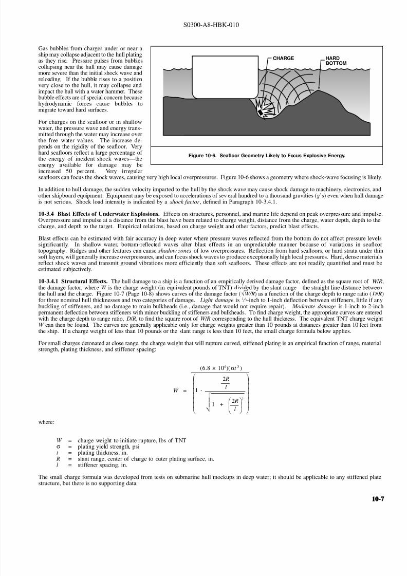
8132019 Articol despre explozii submarine
httpslidepdfcomreaderfullarticol-despre-explozii-submarine 724
S0300-A8-HBK-010
Gas bubbles from charges under or near a
Figure 10-6 Seafloor Geometry Likely to Focus Explosive Energy
CHARGE HARDBOTTOM
ship may collapse adjacent to the hull platingas they rise Pressure pulses from bubblescollapsing near the hull may cause damagemore severe than the initial shock wave andreloading If the bubble rises to a positionvery close to the hull it may collapse andimpact the hull with a water hammer Thesebubble effects are of special concern becausehydrodynamic forces cause bubbles tomigrate toward hard surfaces
For charges on the seafloor or in shallowwater the pressure wave and energy trans-mitted through the water may increase overthe free water values The increase de-pends on the rigidity of the seafloor Veryhard seafloors reflect a large percentage of the energy of incident shock wavesmdashtheenergy available for damage may beincreased 50 percent Very irregularseafloors can focus the shock waves causing very high local overpressures Figure 10-6 shows a geometry where shock-wave focusing is likely
In addition to hull damage the sudden velocity imparted to the hull by the shock wave may cause shock damage to machinery electronics another shipboard equipment Equipment may be exposed to accelerations of several hundred to a thousand gravities (grsquos) even when hull damag
is not serious Shock load intensity is indicated by a shock factor defined in Paragraph 10-341
10-34 Blast Effects of Underwater Explosions Effects on structures personnel and marine life depend on peak overpressure and impulseOverpressure and impulse at a distance from the blast have been related to charge weight distance from the charge water depth depth to thecharge and depth to the target Empirical relations based on charge weight and other factors predict blast effects
Blast effects can be estimated with fair accuracy in deep water where pressure waves reflected from the bottom do not affect pressure levelsignificantly In shallow water bottom-reflected waves alter blast effects in an unpredictable manner because of variations in seaflootopography Ridges and other features can cause shadow zones of low overpressures Reflection from hard seafloors or hard strata under thisoft layers will generally increase overpressures and can focus shock waves to produce exceptionally high local pressures Hard dense materialreflect shock waves and transmit ground vibrations more efficiently than soft seafloors These effects are not readily quantified and must bestimated subjectively
10-341 Structural Effects The hull damage to a ship is a function of an empirically derived damage factor defined as the square root of W Rthe damage factor where W is the charge weight (in equivalent pounds of TNT) divided by the slant rangemdashthe straight line distance betweethe hull and the charge Figure 10-7 (Page 10-8) shows curves of the damage factor ( radicWR) as a function of the charge depth to range ratio ( D R
for three nominal hull thicknesses and two categories of damage Light damage is
1
frasl 2
-inch to 1-inch deflection between stiffeners little if anbuckling of stiffeners and no damage to main bulkheads (ie damage that would not require repair) Moderate damage is 1-inch to 2-incpermanent deflection between stiffeners with minor buckling of stiffeners and bulkheads To find charge weight the appropriate curves are enterewith the charge depth to range ratio D R to find the square root of W R corresponding to the hull thickness The equivalent TNT charge weighW can then be found The curves are generally applicable only for charge weights greater than 10 pounds at distances greater than 10 feet fromthe ship If a charge weight of less than 10 pounds or the slant range is less than 10 feet the small charge formula below applies
For small charges detonated at close range the charge weight that will rupture curved stiffened plating is an empirical function of range materiastrength plating thickness and stiffener spacing
W =
(68 times 106)(σt 3 )
1 -
2 R
l
1 + 2 Rl
2
where
W = charge weight to initiate rupture lbs of TNTσ = plating yield strength psit = plating thickness in
R = slant range center of charge to outer plating surface inl = stiffener spacing in
The small charge formula was developed from tests on submarine hull mockups in deep water it should be applicable to any stiffened platstructure but there is no supporting data
10-10-
8132019 Articol despre explozii submarine
httpslidepdfcomreaderfullarticol-despre-explozii-submarine 824
S0300-A8-HBK-010
The shiprsquos critical machinery and cargo
Figure 10-7 Damage Factors
DR
DR
(b) MODERATE DAMAGE
(a) LIGHT DAMAGE
34 PLATE
34 PLATE
12 PLATE
12 PLATE
14 PLATE
14 PLATE
0
0
01
01
02
02
03
03
W
W
R
R
04
04
05
05
06
05
05
06
06
07
07
08
08
09
09
10
10
11
11
12
12
= CHANGE WEIGHT lbs TNT
= SLANT RANGE
= CHARGE DEPTH
= DAMAGE FACTOR
w
R
D
WR
near the detonation area may be damagedby shock-induced motions For chargesless than 20 pounds only small hull-mounted equipment in the immediate areaof the detonation is likely to suffer damageThe degree of shock damage to be expectedis estimated from the shock factor Theshock factor at the point on the hull nearestthe charge is computed from
where
Shock Factor(SF) = W
R
1 + sinφ2
R = slant range ftW = equivalent TNT charge
weight lbs = charge weight times RE factor
φ = angle between the shortestline from the hull to thecharge and a tangent to the
hull at the point nearest tothe hull as shown in Figure10-8
To determine the allowable charge weightan appropriate shock factor is selected fromTable 10-1 to solve for W
10-342 Linear Charges Linear
W = 4(SF)2 R 2
(1 + sinφ)2
demolition charges are frequently used insalvage Line charges produce a complexpressure field In a horizontal plane arounda freely suspended straight line chargemaximum peak pressures occur about 120degrees from the detonation end of thecharge Pressure decay time is about thesame for a given range regardless of orientation relative to the charge axisPressure-time histories on a vertical planeperpendicular to the line charge are quitesimilar to those for a compact charge of same weight with slightly higher peak pressures (2000 psi at 35 feet from acompact 50 pound charge as opposed to2400 psi at 35 feet from a 25 foot linearcharge with 50 pounds of explosive) Table
Table 10-1 Degree of Damage for Various Shock Factors
Shock Factor Damage
lt01 Insignificant ndash nuisance damage only l ight bulbs fuses etc
01 - 015 Tube relay fuse and light bulb failures general electronic failures piping leaks
and possibly a pipe rupture
015 - 020 Increase in above damage piping ruptures likely machinery misalignments likely
020 General machinery damage
10-2 shows the horizontal distribution of peak pressure at distance of 20 feet from
the midlength of a Navy Mk 8 Mod 2 hosecharge (25-foot rubber hose filled with 50pounds of a 7030 mixture of compositionA-3 and aluminum powder) detonated whilefreely suspended 10 feet below the watersurface in approximately 40 feet of water
10-810-8
8132019 Articol despre explozii submarine
httpslidepdfcomreaderfullarticol-despre-explozii-submarine 924
S0300-A8-HBK-010
In An Exploratory Investigation of the
Figure 10-8 Geometry for Calculating Shock Factor
CHARGE
R
φ
Effects of Underwater Line Charges onShip Plating Naval Ship Research andDevelopment Center December 1967 JKFleming and RE Oliver report that thedeflection of hull plating between stiffenerscaused by Navy Mk 8 Mod 2 hose chargescan predicted approximately by
where R t W and σ are as previously
d = 37 a
Ro σ t
2WLRo
4 R2
o L 2
defined and
d = plating set deflection in L = charge length fta = e ff ec ti ve p la ti ng s iz e
(between stiffeners) in
Table 10-2 Pressure Distribution Around Mk 8 Mod 2 Hose Charge
Gage position (angle between line from gage to midlength
and charge axis with detonation end at 0 degrees)
Peak Pressure
psi20 1300
30 1500
40 1730
50 2100
60 2600
70 3300
80 3730
90 3900
100 4220
110 4620
120 5000
130 4000
140 3960
150 2390
160 2250
170 2400
180 3050
All pressures measured 20 feet from midlength of charge
For rectangular plates effective plating sizeis determined from
where
a = 116
90
1
x 2
1
y 2
x = plate width in y = plate length in
10-343 Multiple Charges Multiplecharges detonated simultaneously aretreated as a single large chargemdashthe totalweight of all charges in the array must beless than the maximum acceptable chargeweight determined as described inParagraph 10-341 for a single charge
For multiple charges detonated individuallywith delays between detonations themaximum acceptable single charge weightis determined Charge weights should be
Figure 10-9 Minimum Delay Between Detonations in Charge Array
CHARGE DEPTH FEET
55 LBS TNT
35 LBS TNT
20 LBS TNT
10 LBS TNT
5 LBS TNT D E
L A Y
T I M E
S
E C O N D S
0
05
10
15
20
25
30
10 20 30 40 50 60
one-third the single charge weight or less toprevent progressive hull damage Aminimum delay time between detonations isnecessary to allow the energy from theprevious detonation to dissipate so structureblast loading is not cumulative Minimumdelay times are taken from Figure 10-9
10-344 Ballasting Water-backed hullsare more resistant to shock damage thanair-backed hulls When internal waterdamage is not a problem and the ship can
contain the water spaces in the vicinity of explosive charges may be ballasted How-ever the first air-backed bulkhead exposedto the explosive loading can incur damageif it is in close proximity to the charge
It is not necessary to flood exactly to thewaterline to increase shock resistance butthere should be several feet of water in anyballasted space and six inches to one foot of air between the water surface and the nextdeck No reliable data are available forpredicting how much the charge weight maybe increased if the ship is ballasted A large bubble collapsing near the hull can cause considerable damage even to water-backed plating
10-10-
8132019 Articol despre explozii submarine
httpslidepdfcomreaderfullarticol-despre-explozii-submarine 1024
S0300-A8-HBK-010
10-35 Effects on Marine Life Environmental protection agencies may require salvors to estimate blast effects on local marine life Lethal
ranges may be specified that will limit charge weight
Lethal range seldom exceeds 650 feet and is estimated by
Table 10-3 Fish Kill Range Constants
Fish Weight Depth of Blast ft K
α
1 oz 10 328 0220
1 oz 50 385 0256
1 oz 200 475 0262
1 lb 10 174 0264
1 lb 50 235 0275
1 lb 200 272 0299
30 lbs 10 86 0284
30 lbs 50 131 0314
30 lbs 200 139 0342
H MAX = KW α
where
H MAX = maximum horizontal range of lethal overpressures
feet
K α = coefficients from Table 10-3
W = charge weight pounds
Although fish kill range can be estimated it is very difficult to keep
fish out of a specified area Bubble screens have been used with
some success
10-36 Safe Distances for Above-water Blasts The minimum
distances to protect personnel against shock wave and overpressure
are
SD = 300 W 13
Bare charges on or in ground
SD = 350 W 13
Charges in rock
where
SD = safe distance ft
W = charge weight lbs TNT = W times RE factor
Fragments and debris may be thrown greater distances and hazard personnel in the open The projectile hazard can be reduced by
bull Greater separation distances
bull Confinement of the explosion at the source
bull Barricades between personnel and the blast site
bull Evacuation of nonessential personnel
bull Overhead cover
10-1010-10
8132019 Articol despre explozii submarine
httpslidepdfcomreaderfullarticol-despre-explozii-submarine 1124
8132019 Articol despre explozii submarine
httpslidepdfcomreaderfullarticol-despre-explozii-submarine 1224
S0300-A8-HBK-010
10-41 Charge Weight Charge weight selection is based on two criteria
bull The charge must be large enough to perform the task
bull The charge must not be so large that it causes unacceptable damage to the casualty nearby structures or the environment
The minimum charge weight that will accomplish the task (in one shot) may be greater than the maximum charge weight what will not causedamage It is usually possible to perform the task in a series of steps each using charge weights smaller than the maximum acceptable weight
10-42 Underwater Blasting Water
Figure 10-11 Shared Charge Cutting Sequence
EXPLOSIVECHARGE
CONTAINER
LINER
CAVITY
SHAPEDCHARGE
(a)
S T A N D
- O F F
DETONA-TION WAVEAPPROACHESCAVITY LINER
(b)SHOCK WAVECOLLAPSESLINER INDUCINGJET FORMATION
(c)
CUTTING JETAPPROACHESTARGETSURFACE
(d) PLASTIC FLOW
IS INDUCED INTHE TARGETMATERIAL ANDTHE JET STARTSTO PENETRATE
(e)
JET PASSESTHROUGHTHE TARGET -CUT ISCOMPLETE
(f)
INITIATORpressure on the side of an object oppositethe explosive blast opposes the impact andexpansion of the explosive When the work involves moving large surface areasresistance to movement caused by waterpressure and hydrodynamic drag issignificant and explosive effectiveness isreduced For example it takes about onepound of explosive to break up and move acubic yard of rock in dry air Two to sixpounds of explosive per cubic yard arerequired to break and move the same rock underwater Explosive effectiveness is
further reduced as depth increases
Steel cutting by ribbon charges shapedcharges etc where little surface movementis required is not significantly affected byimmersion in water Shaped chargeeffectiveness is reduced if water cannot bedisplaced or evacuated from the cavity andstand-off (shaped charges are discussed inParagraph 10-421)
Most explosives detonate satisfactorilyunder water Some explosives containwater-soluble ingredients and aredesensitized with time when immersedunless sealed in waterproof containers
Certain explosives depend on dispersed microscopic air or gas bubbles for ease of initiation Immersion in deep water compresses the bubblesand renders them ineffective so they can be used only in shallow water or if specially formulated for deep water use Explosives dependingon dispersed bubbles for initiation include those based on or sensitized by nitroglycerine and nitroglycerol such as gelignites and blastinggelatins and those containing aqueous solutions of ammonium nitrate such as water gels and emulsions
Most military high explosives and commercial explosives based on PETN RDX and TNT can be used reliably in deep water because theyare not are not significantly water-soluble and do not depend on gas bubbles for initiation
Overlying water is an effective tamping agent but if the charge is not in intimate contact with the target the intervening water layer will largelynegate the tamping effect Even a thin water layer between the charge and target will dissipate some of the explosive energy before it reachesthe target The shock and compression waves pass through two media interfacesmdashexplosive to water and water to target energy is reflectedaway from the target at each interface If charges cannot be placed in intimate contact with the work additional tamping in the form of sandbags clay or soil should be used to overcome the dissipation of energy by the intervening water
Potential water tamping lends a slight theoretical advantage to blasting from the wet side of a hull but offsetting advantages accrue whenexplosives are placed in the dry
bull Explosives fuses and initiators are not subject to the desensitizing effects of water immersion or to disturbing forces of currentand surge
bull Charges can be placed more effectivelymdashit is easier to secure charges and intimate contact with the target surface can be attained
bull Charges and firing circuits can be inspected immediately before firing
bull There is greater control over the personnel placing explosives and their work can be monitored and inspected with less effort
Immersion time prior to firing should be minimized to reduce the desensitization of the explosives and the possibility that current or surge willdislodge charges or initiating circuits
10-1210-12
8132019 Articol despre explozii submarine
httpslidepdfcomreaderfullarticol-despre-explozii-submarine 1324
S0300-A8-HBK-010
10-43 Cutting and Fracturing Charges A principal use of explosives in salvage is cutting hull plating and structure in ships High-velocitybrisant explosives such as TNT and plastic explosives are best for cutting steel or aluminum Structural members are cut by a variety ocharges
bull Shaped charges ndash A lined or unlined cavity in the explosive produces a high-energy cutting jet
bull Fracturing charges ndash Specialized charge geometry causes convergence of strain waves in the target
bull Simple contact charges ndash Breakage is accomplished by the combined but uncoordinated effects of shock waves strain pulses angas expansion
Shaped and fracturing charges are far more efficient than contact charges and should be used when available and when suited to working conditions Because of their relatively small charge weights shaped and fracturing charges must be placed precisely and must be held in positioagainst current or surge to be effective If charges cannot be placed precisely better results may be obtained with less efficient contact charge
10-431 Shaped Charges A hollowed-
Figure 10-12 Typical Shaped Charges for Salvage Work
FLEXIBLE LINEARSHAPED CHARGE
BOX TYPELINEAR CHARGE
EXPLOSIVE
TARGET
CASE
METALLINER
ENCLOSED
STAND-OFFSPACE
CYLINDRICALCHARGE
EXPLOSIVECORE
DENSEFLEXIBLE
SHEATH
WOODENSPOOL
out or shaped charge detonated against ahard surface produces a crater that isapproximately a mirror image of the chargecavity The shaped charge is initiated at apoint behind the cavity the detonation waveexpands omnidirectionally from theinitiation point or axis Reaching the cavitythe detonation wave converges on a plane
(for linear charges) or axis (in cylindricalcharges) perpendicular to the target surfaceThe convergence of the shock waveconcentrates the explosive energy in a smallarea The resultant cratering is called the
Munro Effect If the charge is lined withmetal or other dense material the explosioncollapses the liner and carries it in the shock wave to the target surface as a slug (orblade) of metal and hot gas that acts as acutting jet The jet heats and erodes thetarget surface Shock-wave pressure and jeteffects combine to induce plastic flow in thetarget and cut through the material Figure10-11 illustrates the cutting sequence for alined shaped charge
For optimum effect shaped charges arepositioned at a stand-off distance from thetarget surface to allow the penetration jet toform completely before it reaches the targetsurface Optimum stand-off varies with thecavity angle and charge size stand-off isd et er m in ed f r om t ec hn ic al o rmanufacturerrsquos data for the charge used
Various-sized cylindrical shaped chargesare made for hole cutting Linear chargesare used for long cuts Linear charges areusually made in the form of a box with thecavity liner set across the inside of the boxas shown in Figure 10-12 Flexible linearshaped charges can conform to irregular
surfaces and cut lines Well-designedlinear cutting charges obtain good resultswith relatively small charge weightsIndividual charge weight and explosiversquosconsumption are based on data publishedfor the particular explosives used Data formilitary shaped charges is given in the Technical Manual for the Use of Explosives in Underwater Salvage (NAVSEA SW061-AA-MMA-010Typical manufacturerrsquos data for linear shaped charges are shown in Figure 10-13 (Page 10-14)
10-110-1
8132019 Articol despre explozii submarine
httpslidepdfcomreaderfullarticol-despre-explozii-submarine 1424
S0300-A8-HBK-010
Shaped charges can be improvised as
Figure 10-13 Typical Manufacturerrsquos Data for Linear Shaped Charges
STAND-OFF FOR OPTIMUM PERFORMANCE(RDX OR PETN EXPLOSIVE)
MINIMUM CUTTING PERFORMANCEAT OPTIMUM STAND-OFF
MINIMUM CUTTING PERFORMANCEAT OPTIMUM STAND-OFF
MINIMUM CUTTING PERFORMANCEAT OPTIMUM STAND-OFF
MINIMUM CUTTING PERFORMANCEAT OPTIMUM STAND-OFF
5
30 15
10
05
02
01
2010
JETCORDSTAND-OFFTARGET
05
02
01
05
0201
01
02
05
01
02
01
02
05
10
20
02
05
01
02
05
10
1 0
2 0
3 0
4 0
5 0
1 0 0
2 0 0
EXPLOSIVE CORELOAD GRAINSFOOT
EXPLOSIVE CORELOAD GRAINSFOOT
EXPLOSIVE CORELOAD GRAINSFOOT
EXPLOSIVE CORELOAD GRAINSFOOT
NOTE CUTS AT 7 AND 10 GRFTMADE AT ZERO STAND-OFF
EXPLOSIVE CORELOAD GRAINSFOOT
100
5
5
10
10
50 100 200 500 1000
20
20
50
50
100
100
200 500
200 500 1000 2000 5 0 0
S T A N D
- O F F I N C H E S
T H I C K
N E S S
C U T
I N
C H E S
T H I C K N E S S
C U T
I N
C H E S
T H I C K N E S S
C U T
I N
C H E S
T H I C K N E S S
C U T
I N
C H E S
1 0 0 0
2 0 0 0
A L U M
I N U M
S H E A
T H
C O P P
E R S H E A
T H
L E A D
S H E A
T H
C 1 0 1 8 S T E E
L T A R G
E T
COPPER-SHEATHEDJETCORD (RDX ORPETN EXPLOSIVE)
LEAD-SHEATHEDJETCORD (RDX ORPETN EXPLOSIVE)
2024-T351ALUMINUM
TARGET
C10118STEELTARGET
2024-T351ALUMINUM
TARGET
C10118STEELTARGET
ALUMINUM-SHEATHEDJETCORD (RDX
OR PETN EXPLOSIVE)
SILVER-SHEATHEDJETCORD
(DIPAMEXPLOSIVE)
CUT7075-T6
ALUMINUMTARGET
OPTIMUMSTAND-OFF
shown in Figure 10-14 When performance
data for a particular material is not
available cutting ability can be estimated
from the following
where
t = t o
ρρ
o
t = unknown cutting capacity
(thickness) in material of
density ρt o = known cutting capacity in
material of density ρo from
manufacturerrsquos data
Water in the stand-off and cavity prevents
the formation of the cutting jet Theenclosed stand-off of box-type shaped
charges excludes water but boxes can
withstand hydrostatic pressures only to
shallow depths that vary with the particular
unit For depths of 30 to 60 feet the stand-
off can be filled with closed-cell plastic
foam The foam inhibits jet formation
slightly so that performance is decreased
For deeper immersion the stand-off and
cavity must be constructed to withstand
hydrostatic pressure or made free flooding
and then evacuated with compressed air or
gas at depth For underwater use flexible
linear charges can be enclosed in flexibletubes filled with foam or evacuated by
compressed gas One manufacturer markets
a line of circular cutters prefabricated with
compressed gas fittings
10-432 Fracturing Charges A diamond-shaped sheet of plastic explosive laid on a steel plate and detonated simultaneously from two
opposite corners will fracture the metal along a line between the two uninitiated corners This effect is shown in Figure 10-15(a) The fracture
mechanism depends on the pressure rise as the shock waves from the two detonating points collide followed by the relaxation as the waves
pass through one another and the combined effect of two tension waves rebounding from the far side of the target This arrangement is a
diamond charge and is suitable for cutting bars and pipes but has limited application for plate cutting because the fracture extends only slightly
beyond the charge
The diamond charge principle was first applied to extended plate cutting in fracture tape Fracture tape shown in Figure 10-15(b) consists of
a series of diamond charges connected by continuous strips of explosive along the edges of the charges Fracture tape has seen only limiteduse because it was not manufactured in a flexible form The charge may fail to cut if bilateral asymmetry develops between the two initiation
trains Fracture tape can be improvised by cutting explosive sheet to the appropriate shape
Shock-wave refraction tape (SRT) is a recently developed explosive charge that works on the principle of shock-wave collision within metal
targets In this charge a continuous strip of explosive is molded to the back of an inert wave-shaping element as shown in Figure 10-15(c)
One manufacturer uses magnetic rubber as the wave-shaping element providing both flexibility as well as an attachment method (provided the
surfaces are clean and smooth) The performance of shock-wave refraction tape is comparable to that of shaped charges when cutting ordinary
steels very high strength fracture-resistant steels may not be cut as easily There is no cavity or stand-off to flood so SRT is more adaptable
to underwater use than linear shaped charges
10-1410-14
8132019 Articol despre explozii submarine
httpslidepdfcomreaderfullarticol-despre-explozii-submarine 1524
S0300-A8-HBK-010
Figure 10-14 Improvised Shaped Charges
SHEETEXPLOSIVE
STEEL ORALUMINUM
ANGLE
PLASTICEXPLOSIVE
PLASTICEXPLOSIVE
CONE
WINEBOTTLE
STICKS TAPEDTO SIDE ASSTAND-OFF
FUSE
CAP
S T A N D - O
F F
D I S T A N C E
FOOD CANWITH BOTHENDS CUT
OUTPLASTICEXPLOSIVE
SHEETMETALOR LEADSHEETCONE
RIVET
SIDES OFCAN FORMSTAND-OFF
CAP
80˚ - 90˚
Figure 10-15 Fracturing Charges
A
Arsquo
A ArsquoEXPLOSIVE
FRACTURE
EXPLOSIVESHOCK-WAVEFRONTS
REFLECTEDTENSION WAVE
(a) DIAMOND CHARGE (INITIATED AT POINTS A AND Arsquo)
(c) SHOCK-WAVE REFRACTION TAPE (SRT)(b) FRACTURE TAPE
EXPLOSIVE
INERT BARRIERSINITIATION POINT
EXPLOSIVE
WAVE-SHAPINGELEMENT
FRACTURES TENSIONWAVE
SHOCK WAVE
10-110-1
8132019 Articol despre explozii submarine
httpslidepdfcomreaderfullarticol-despre-explozii-submarine 1624
S0300-A8-HBK-010
10-433 Contact Charges Simple
Figure 10-16 Steel Cutting Contact Charges
DETONATINGCORD
EXPLOSIVE
STEEL PLATE
WELDS
STEELCHANNEL
STUD
PLATE
SECURINGSTRAP
EXPLOSIVESHEET OR
PLASTICEXPLOSIVE
contact charges require much heaviercharges than shaped or fracturing chargesExplosive performance can be increasedand charge weight reduced by carefulcharge placement confinement tampingand by scoring cut lines with cuttingtorches or mechanical cutters Some
effective charge placements and geometryare shown in Figure 10-16
Charge weights can be estimated from thefollowing relationships
where
W = 3
8 A Structural steel
W = D 2 High carbon or alloy steel
W = charge weight lbs TNT
A = cross-sectional area of sectionto be cut in2
D = diameter or thickness of section to be cut in
To determine charge weights for explosivesother than TNT the TNT charge weight isdivided by the relative effectiveness (RE)factor
10-434 Charge Placement Cutting charges are most effective when the cut line is adjacent to but not on a rigid portion of the target surfaceThe target must be restrained from moving away from shaped and fracturing charges so the explosive energy is expended in cutting or fracturingthe target rather than pushing it away Contact charges create a strong shearing action along the line between the movable and rigid surfaceHull cutting charges are most effective when slightly offset from frames
bull If placed in the middle of the span a large portion of the explosive energy is expended in deflecting the plate
bull If placed directly over a stiffener both the stiffener and the plate must be cut
For efficient cutting charges must be placed in intimate contact with the target surface Charges must be secured to all vertical steeply angledand overhead surfaces and to horizontal surfaces where current wind vibration or target movement may dislodge them Where no tie-downpoints exist the following securing methods can be used
bull Light metal straps bolted to studs explosively set or friction welded along each side of the cut line
bull Tie-down wires lines or bongee cords inserted through holes cut drilled or burned through the plating (tie-downs can also beled to studs or magnetic clamps)
bull Sandbags or similar weights placed on charges on horizontal surfaces
bull Backing charges with magnetic strips adhesive strips or small suction pads (these methods have had limited success)
bull Hose charges can be stretched between tie-down points over flat or smoothly convex surfaces
10-435 Ship Sectioning Explosives are commonly used to section wrecks for piecemeal removal or to separate a casualty into two piecesso that one part can be salvaged Ship sectioning including explosive methods is discussed in the US Navy Ship Salvage Manual Volume 2(S0300-A6-MAN-020) The following notes supplement that discussion
10-1610-16
8132019 Articol despre explozii submarine
httpslidepdfcomreaderfullarticol-despre-explozii-submarine 1724
S0300-A8-HBK-010
When cutting a ship transversely the internal structure must be cut as well as the more accessible hull plate and stiffeners It is very difficu
to obtain complete separation in a single shot Salvors should plan to make cuts in several shots or have thermal or mechanical cutting gea
available to sever stubborn structure
In a landmark operation in 1973 the salvageable aft section of a 960-foot laden ore carrier was explosively separated from the forward part o
the ship which was abandoned The ship had sunk by the bow in 130 feet of water With holds 7 8 9 and 10 their associated wing and
double-bottom tanks and the machinery spaces dry the after section was buoyant and afloat The hull was cut in way of number 7 hold b
more than 1800 feet of custom engineered and fabricated high speed explosive cutters All cutters were placed in the dry number 7 wing anbottom tanks Instantaneous separation (necessary to prevent capsize of or damage to the aft section) was attained by
bull Placing cutters against all bulkheads shell plating stringers void tank sections and pipes extending through the transvers
bulkhead separating holds 7 and 8
bull Taking advantage of the vertical shear on the hull resulting from the weight of the forward section laden with 90000 tons of ore
and the buoyancy of the after section and
bull Maintaining a 300-ton horizontal astern pull on the after section as the cutters were detonated
Blast curtains were rigged in the number 7 tanks and hold and the number 8 wing and bottom tanks were pressurized with compressed air to
protect the separating bulkhead A diverrsquos survey after the successful separation revealed no damage to the bulkhead The operation was mad
possible by the salvorsrsquo employment of specialist explosives engineers who custom designed the explosive cutters taking into account permissiblblast effects on the aft number 7 bulkhead gas generation and dispersion requirements mutual interference between charges and the strength
of hull structural members See The Cutting of the Igara in Reedrsquos Commercial Salvage Practice for a more detailed discussion of th
operation
The order in which the different members are to be cutmdashas well as the methods to be usedmdashmust be considered carefully Preliminary cut
should not weaken the structure to the point that it is in danger of collapsing and injuring personnel placing charges for subsequent cuts
Cutting methods are frequently combined A hull can be opened up with explosives to permit access to internal structure to be cut by mechanica
or thermal methods In some cases preparatory weakening cuts are made by divers with oxy-arc or exothermic torches with the final cuts mad
explosively
Simple types of ships are better candidates for explosive sectioning than more complex types The following ship types lend themselves t
explosive sectioning
bull Transversely framed ships because there are fewer longitudinal stiffeners to cut
bull Freighters and bulk carriers because most do not have centerline longitudinal bulkheads (some bulk carriers have wing tanks whos
inner bulkheads must be cut) Small ships often do not have double bottoms
bull Small single-product tankers because they do not have wing tanks or double bottoms
The following ship types are not good candidates for explosive sectioning
bull Longitudinally framed ships because of the large number of longitudinal stiffeners
bull Passenger ships and warships because of their extensive joiner work internal subdivision wireways piping and ventilatio
systems
bull Large tankers and product carriers because they are constructed with two or more longitudinal bulkheads
bull Freighters with insulated holds
10-110-1
8132019 Articol despre explozii submarine
httpslidepdfcomreaderfullarticol-despre-explozii-submarine 1824
S0300-A8-HBK-010
10-44 Seafloor Blasting Seafloor
Figure 10-17 Obstruction Blasting
CONTACT BLASTING MUDCAPPING
SNAKEHOLING
STEMMINGSTEMMING
CHARGE
CHARGE
BLOCKHOLING
blasting moves large amounts of seafloor
material by channeling trenching etc or
removes isolated obstructions such as
pinnacles coral heads and boulders The
basic techniques are
bull Contact Blasting ndash Chargesare placed on the formation
to be blasted either indi-
vidually or in line or
checkerboard patterns The
detonating explosive imparts
a violent blow to the seafloor
material The efficiency of
contact blasting depends on
maintaining intimate contact
with the material to be
blasted Contact blasting is
the least efficient blasting
method in terms of explosive
consumption but requires the
least time and effort to
prepare and set charges
bull Boreholes ndash Internal charges
are placed in boreholes
drilled or augured into the
object or strata to be blasted
10-441 Rock Blasting The choice of explosive for a particular rock-blasting job depends on the hardness and density of the rock and the
type of breakage desired Fast brisant explosives such as TNT or composition C-4 are required to break most kinds of rock although slower
explosives are effective on soft rock such as limestone
Rock is weakest in tension so internal charges are most effective Contact blasting depends on the tamping effect of overlying water to confine
the explosion momentarily and is effective only on soft rock and coral where the material is broken by crushing rather than shattering The
rock fragments are moved by the expanding gases so high gas production is required to move dense rock If the object is to break up rock for
removal by nonexplosive means gas production of the explosive is less important Individual boulders are broken by one of the methods
discussed below The methods are illustrated in Figure 10-17
bull Mudcapping ndash A contact charge is covered with 10 to 12 inches of mud clay or moist soil tamping Plastic clay is the most
effective tamping Loose sand should not be used but sandbags are effective
bull Snakeholing ndash The charge is placed in a hole jetted bored or otherwise excavated under an object lying on or partially buried
in a soft seafloor Snakeholing is more effective than mudcapping under all conditions and requires about one-half as much
explosive as contact blasting
bull Blockholing ndash The charge or charges are placed in one or more boreholes Explosive effect can be altered by changing charge
weights and placement rock formations boulders concrete structures etc can be completely demolished be broken into
fragments of varying size or have portions broken off Blockholing requires about one-third as much explosive as contact blasting
Table 10-4 gives approximate explosive requirements in pounds per
Table 10-4 Powder Factors (lbyd3) for Rock Blasting
Blas ting Metho d A ir B la sting Und erwater Blas ting
Contact Blasting Not effective 6 - 20
Mudcapping 1 - 2 4 - 15
Snakeholing 1 - 11 frasl 2 3 - 10
cubic yard or powder factor for different rock-blasting methods A
range of powder factors for each method is given The actual powder
factor for any project will depend on
bull The relative density and toughness of the rock
bull Whether individual boulders or massive rock formations
are being blasted
bull Water depth
10-1810-18
8132019 Articol despre explozii submarine
httpslidepdfcomreaderfullarticol-despre-explozii-submarine 1924
S0300-A8-HBK-010
The lower values in Table 10-4 are based
Table 10-5 Rock Density and Toughness
Type of Rock Density lbft3 Relative Toughness (Limestone = 1)
Andesite 150 - 175 11
Basalt 150 - 200 17 - 23
Conglomerate 125 - 162 NA
Dioritic 156 - 200 19 - 21
Felsite 150 - 200 NA
Gabbro 169 - 200 NA
Granite 156 - 194 15 - 21
Gneiss 150 - 181 10 - 19
Limestone 160 - 187 10
Marble 131 - 181 NA
Quartzite 125 - 200 19 - 27
Sandstone 124 - 194 15 - 26
Schist 150 - 175 10 - 21
Shale 112 - 194 NA
Slate 156 - 194 12
on blasting massive limestone at depths of 30 to 60 feet Values high in the range areused with tougher or denser rocks andgreater depth Lower values are used whenblasting individual boulders or outcrop-pings Table 10-5 compares densities andtoughness of common rocks
Rock blasting by internal charges is mosteffective when there is a free face approxi-mately parallel to the borehole Thedetonation of the explosive creates a highgas pressure in the charge hole generating acompressive strain pulse in the surroundingrock The compressive pulse travels outwardin all directions Near the hole theamplitude of the strain pulse is sufficient tocrush the rock Amplitude decays rapidly asthe pulse travels outward until it can nolonger crush the rock The pulse travels out-ward until it is reflected from a free surfaceas a tensile strain pulse As rock is much
Figure 10-18 Excavation Rock Blasting
DRILLING FACE
WORKING OR FREE FACE
BOREHOLE
BENCH
EXCAVATION FLOOR(PROJECT DEPTH)
L
B
BltL
INSUFFICIENT EXPLOSIVEENERGY RELEASE AT
BOTTOM OF HOLE
B
MAINFRACTURELINES
COLUMN LOADEDHOLE
45˚
STRESS PATTERN FOR ACONCENTRATED CHARGE
IN BOTTOM OF HOLE
REFLECTEDTENSION WAVE
UNREFLECTEDCOMPRESSIONWAVE
TOE
weaker in tension than compression the
tensile pulse is able to break the rock pro-gressing from the free face back towards thecharge hole The expanding gases in thecharge hole are not directly responsible formuch of the rock breakage to some extentthe rock is pulled apart rather than pushedapart
Blasting massive seafloor rock formations issubject to constraints similar to those en-countered in quarry blasting and similarmethods are employed Detailed informationon rock blasting is found in publications onmining and quarrying For effective blastingit is necessary to establish a breaking orworking face at an angle to the drilling faceThe drilling face is most often the horizontalseafloor the working face is vertical orinclined from the vertical by an angle of 45degrees or less The working face is brokenback in steps by detonating charges in rowsof holes behind the face For cuts deeperthan the maximum practical drilling depththe working face is broken back in stages byestablishing intermediate floor levels orbenches as shown in Figure 10-18
A working face can be established in aflush surface by blasting out a crater with asingle charged hole cluster of holes or lineof holes Empty relief holes between andaround charged holes provide free faces toreflect strain pulses and space for displaced
rock to move into The excavation floorand work face can be squared up bysubsequent blasting
Boreholes can be drilled by diver-operated jackhammers or rock drills for smalloperations For extensive drillingoperations a spud-moored drill barge or asubmersible crawler-mounted rock drillshould be used
10-110-1
8132019 Articol despre explozii submarine
httpslidepdfcomreaderfullarticol-despre-explozii-submarine 2024
S0300-A8-HBK-010
10-442 Coral Blasting Coral is difficult
Figure 10-19 Coral Blasting
13
13
12
12
11
11
10
10
9
9
8
8
7
7
6
6
5
5
4
4
3
3
2
2
1
1
0
0
DEPTH AND WIDTH OF CUTS MADE IN CORAL WHEN BLASTING WITH CAVITY CHARGES
DEPTH AND WIDTH OF CUTS MADE IN CORAL BY STANDARDUS MARK 8 DEMOLITION CHARGES
VOLUME OF CORAL REMOVED USING9-KG (20 POUND) CHARGES
CRATER WIDTH IN FEET
CRATER WIDTH IN FEET
NUMBER OF PACKS
V O L U M E
I N
C U B I C
F E E T
1 2 3 4 5
1
1
2
2
3
3
4
4
5
5
6
6
7
7
8
8
9
9
10
10
11
11
12
12
13
13
1
1
2
2
3
3
4
4
5
5
100
20
30
40
50
60
70
80
90
100110
D E P T H
I N
F E E T
D E P T H
I N
F E E T
to blast because of its porosity High-velocity explosives have been successfulbut slow-detonating explosives are moreeffective Coral will clog rock drills sointernal charges are set in powder points(pipes driven into the formation) Powderfactors for coral are about five pounds per
cubic foot for mushroom-shaped coralheads and higher for solid headsDemolition of an above-water coralformation requires about three times asmuch explosive as an equivalent underwaterformation unless a well-placed thoroughlytamped internal charge is used Linecharges can be used to cut trenches orchannels in coral Figure 10-19 showstypical results of coral blasting
10-443 Blasting ImpalementsRemoving an impaling rock or coral head isa slow and tedious process The chargesmust be large enough to break the rock orcoral but light enough that they do not
damage the ship or drive the impalementfurther into the ship The only feasibleprocedure is to begin with very smallcharges and check the results after eachshot Charge size can be increasedincrementally if there is no hull damage orthe same charge can be repeated until theimpalement is gradually severed or brokenaway A large internal concrete patch overthe impalement and surrounding platingstrengthens the hull against shock loadingso that larger charges can be used Theimpalement should be cut off about twofeet below the hull
When external access to the impalement isdangerous or impossible the impalement isattacked from the inside The bestprocedure is to use small charges inshallow boreholes with interspersed relief holes to progressively shatter theimpalement and lower it sufficiently toclear the hull Doors and hatches should beopen during blasting to prevent the hull from being pressurized internally by the explosive gases It may be necessary to build a trunk aroundthe impalement to provide a watertight enclosure and to vent explosive gases to the atmosphere
10-444 Setting Anchors Anchors can be set in hard pan coral clay or mud bottoms with explosives Small charges are set near the anchoras shown in Figure 10-20 and detonated The anchor is lifted and dropped into the blast crater At the same time a quantity of loose or brokenseafloor is lifted out of the crater and some of this material will settle on the anchor Anchors can be explosively settled into seafloors subjectto liquefication under high-frequency cyclic loading such as clean medium- or low-density cohesionless soils A number of small chargesdetonated sequentially on short delay in the vicinity of the anchor can liquefy the soil allowing the anchor to settle into the seafloor underits own weight
10-445 Channeling in Soft Bottoms Military dynamite or other low-velocity low-brisance explosives are best for moving soft plasticmaterial Powder points contact charges charges in augured or excavated holes or hose charges in checkerboard or linear patterns are usedContact blasting will normally dig a channel or crater four to five feet deep Deeper cuts can be attained by driving powder points to the desiredchannel depth plus the distance between points Powder factors are three to five pounds of explosive per cubic yard of soil Alternate pointsshould contain charges of different weights so that the detonation waves do not cancel one another Soft seafloors are almost always excavatedmore effectively by nonexplosive means such as dredging or scouring
10-2010-20
8132019 Articol despre explozii submarine
httpslidepdfcomreaderfullarticol-despre-explozii-submarine 2124
S0300-A8-HBK-010
10-45 Concrete and Masonry Blasting
Figure 10-20 Setting Anchors with Explosive Charges
CHARGESANCHOR
FIRING SYSTEM BLASTING CAP
BUOY
DETONATING CORD MADEUP TO WORKING LINE
LIGHT LINE TO KEEP STRAINOFF DETONATING CORD
Concrete and masonry are blasted by thesame methods as rock Simple concretedispersal requires about one pound of explosive per cubic foot Breachingcharges for concrete and masonry structuresare estimated by
W = R
3
KC where
W = charge weight lbs TNT R = breaking radius ft
= thickness for externalcharges
= distance to outside surfacefor internal charges
K = material factor from Table10-6
C = tamping factor from Figure10-21 (Page 10-22)
10-46 Timber and Pile Cutting Forcutting timber high-velocity brisant
explosives work best but low-velocityexplosives are effective when appliedproperly Charge weights vary as thesquare of the diameter of the timberEmpirical relationships for determiningcharge weights are given below
where
W = D 2
4Untamped external charges
W = D 2
250Tamped internal charges
Table 10-6 Material Factor K for Concrete Breaching Charges
Material R K
Poor masonry shale and hardpan All values 0225
Good masonry ordinary concrete rock
Less than 3 ft
3 to 5 ft
5 to 7 ft
More than 7 ft
035
0275
025
0225
Dense concrete first-class masonry
Less than 3 ft
3 to 5 ft
5 to 7 ft
More than 7 ft
045
0375
0325
0275
Reinforced concrete (concrete only will
not cut reinforcing steel)
Less than 3 ft
3 to 5 ft
5 to 7 ft
More than 7 ft
070
055
050
0425
W = charge weight lbs TNT D = diameter of round or leastdimension of dressedtimber in
For explosives other than TNT chargeweight is determined by dividing the TNTcharge weight by the relative effectiveness(RE) factor
10-47 Reducing Underwater ShockWave Pressure and Impulse Shock waves damage structures by two differentmechanisms
bull The peak shock wave pressureexceeds the compressive strengthof the material
bull The impulse causes structural elements to vibrate with their natural frequency The deflection may be great enough to cause damageImpulse caused vibrations can cause damage even when the peak pressure does not exceed the compressive strength of the material
Shock wave pressure or impulse at a structure can be reduced by charge placement bubble screens and in the case of multiple charges firingsequence
10-210-2
8132019 Articol despre explozii submarine
httpslidepdfcomreaderfullarticol-despre-explozii-submarine 2224
S0300-A8-HBK-010
10-471 Charge Placement Observations
Figure 10-21 Tamping Factor C for Concrete Breaching Charges
C = 45
C = 25 C = 20 - 25
C = 23C = 35
C = 20 C = 15
C = 25
UNTAMPED CHARGES
TAMPED CHARGES
R
R R
R
R
R R
R
t 03tltdltt
D
C = 125C = 125
STEMMED PLACED IN
CENTER OFMASS
C = 125 - 10
R
t dgtt
DR
R
FILL
Figure 10-22 Shock Wave Effects for Various Blasting Conditions
NOTE
620PSI
50PSI
29PSI
14 MS
13 MS
2 MS
(a) 33 FT FROM 1LB CHARGEIN FREE WATER
EXTRAPOLATED FROM DATAFOR POINT 47 FT FROM 3LBCHARGE IN FREE WATER
NOTEEXTRAPOLATED FROM DATAFOR POINT 47 FT FROM 2LBCHARGE IN 29 FT3 OF ROCK
(b) 33 FT FROM 1LBCHARGE IN ROCK
(c) 33 FT FROM 1LB CHARGEIN FREE WATER THROUGHBUBBLE SCREEN(0043 FT3SEC PER FT)
of underwater rock blasting operations haveshown that peak pressures for explosiveswell packed in bore holes is much less thanthat of charges in the water Figure 10-22compares time pressure curves 33 feet froma one pound charge in free water and thesame sized charge in submerged rock Thegreat difference in peak pressures and totalimpulse indicates that a principal means of reducing underwater shock wave effects isto ensure that charges are not detonated whileexposed to free water In seafloor orobstruction blasting internal charges shouldbe used The top portions of boreholes fora distance of 15 times the borehole diametershould be left uncharged Blasting patternsshould be arranged to avoid sympatheticdetonation and ensure that charges to bedetonated later in a firing sequence are notexposed by rock breakage from earlierdetonations Heavy sandbag or clay tampingover cutting charges can significantly reduceshock effects in the surrounding area
10-472 Bubble Screens An impingingshock wave compresses the bubbles of abubble screen over a period of somemilliseconds On their subsequent re-expansion over a period of milliseconds thebubbles emit new compression waves withlower peak values The part of the shock wave that passes between the bubbles isalso attenuated Increasing the number of air bubbles increases the reduction in peak pressure but also increases the duration of the pressure on the side of the bubblescreen away from the blast Investigationsby AT Edwards at the Hydro-electricPower Commission of Ontario showed thatthe peak pressure 33 feet from a one poundcharge was reduced by a factor of 10 by anintervening bubble screen produced by anair flow of 0043 cubic feet per second perfoot of pipe Doubling the air flow reducedpeak pressure by a factor of 70 at the samedistance with the same charge weight At164 feet the corresponding reductionfactors were 8 and 40 Three inchdiameter pipe was used in the experimentswith groups of two diametrically opposite1 frasl 16-inch holes spaced 3 frasl 4-inch or 11 frasl 2 inchesapart Figure 10-22 shows the pressure-time history 33 feet from a one poundcharge with an intervening water curtain
In reducing peak pressure while simultan-eously extending the decay time the bubble
screen redistributes but does not decrease to-tal impulse Bubbles screens are ineffectivein preventing damage in most cases wherethe damage mechanism is primarily impulse
10-473 Firing Sequence In multiple-charge shot-delay shots firing the chargesclosest to the structure to be shielded firstwill reduce the impulse transmitted to thestructure by the delayed charges Theimpulse from the delayed charges is partlyscreened off by explosion gases (and brokenrock when seafloor blasting) from earliercharges
10-2210-22
8132019 Articol despre explozii submarine
httpslidepdfcomreaderfullarticol-despre-explozii-submarine 2324
S0300-A8-HBK-010
10-5 PERMITS
Authorization from the appropriate fleet commander is required for all underwater explosives detonations OPNAVINST 85302 lists the basi
requirements to be met before using demolitions Amplifying instructions in the 8530 series have been issued by fleet commanders
Some of the additional permits required from various Federal and local agencies are described in the following paragraphs It may take man
months to obtain all the required permits Planning for explosives operations should start well in advance and be coordinated carefully so thaall permits are valid over the desired time frame and that other salvage tasks that proceed sequentially or concurrently with the explosive
operations are ready on schedule
10-51 Corps of Engineers Section 10 of the River and Harbor Act of March 3 1899 (30 Stat 1151 33 USC 403) prohibits the obstructio
or alteration of any navigable water of the United States without authorization from the Secretary of the Army Requirements for and limitation
of permits are described in Title 33 of the US Code of Federal Regulations (33 CFR) Article 209120 Detailed information concerning th
permits required for a specific project can be obtained from the local Corps of Engineers Office or from the Department of the Army Offic
of the Chief of Engineers Washington DC 20314
10-52 Environmental Impact Statement Explosives projects that may have an adverse effect on the environment may require the filing o
an Environmental Impact Statement Information on the filing of the statement is found in OPNAVINST 50901 (series)
10-53 State and Local Agencies The number and kind of permits required for explosives operations varies widely from location to location
A partial listing of agencies that may require permits includes
bull State Fish and Game Commission
bull State Lands Commission
bull State Oil and Gas Commission
bull StateEnvironmental Commission Department of Environmental ManagementEnvironmental Protection Agency or similar agency
bull County Board of Supervisors
bull Local police or sheriff
bull Fire Marshal
bull City Engineer
10-6 OPERATIONAL NOTES
10-61 Test Shots Because of the imprecise nature of charge weight and blast effect calculations test shots should always be made before
or at the beginning of an explosives job Test shots are made to determine two quantities
bull The minimum charge weight required to perform the task
bull The maximum charge weight that will not cause unacceptable damage to the casualty nearby structures or the environment
Tests to determine minimum charge weight should be conducted well before the operation at an explosives range or remote site
The maximum acceptable charge weight is estimated by calculation and verified by on-site test shots Test shots are usually conducted as th
first working shots Test shots start with charges lighter than those calculated for the job gradually increasing the charge weights until th
minimum charge weight to perform the task is reached or blast effects become unacceptable
10-210-2
8132019 Articol despre explozii submarine
httpslidepdfcomreaderfullarticol-despre-explozii-submarine 2424
S0300-A8-HBK-010
10-62 Explosives Expertise The importance of seeking the advice of experienced hands for explosives projects cannot be overemphasized
There is no program in the US Navy to train or certify salvage demolitions specialists Navy first class divers and diving officers receive
limited explosives demolitions training Explosive ordnance disposal (EOD) divers and special warfare swimmers (SEAL) receive additional
training in specialized procedures that are not always applicable to salvage The particular demolitions expertise of a Navy diver is a function
of on-the-job experience that may vary from extensive to none In the absence of personnel experienced in salvage demolitions advice may
be sought from Navy Mobile Construction Battalions or the Army Corps of Engineers Commercial explosives consultants may be retained
through the Supervisor of Salvage
10-63 US Military Explosives A wide variety of explosives in various types of demolition charges are maintained in the system for use
by military forces These explosives and charges are described in the Navy technical manuals Use of Explosives in Underwater Salvage
(NAVSEA-SW061-AA-MMA-010) and Demolition Materials (NAVSEA OP 2212) and the Army field manual Explosives and Demolitions (FM
5-25) A summary of the characteristics of US Military explosives is given in Table 10-7
Table 10-7 Characteristics of Military Explosives
Explosive Typical Uses
Rate of Detonation
(Feet per Second)
Relative Effectiveness as
an External Charge
(TNT = 100)
Intensity of
Toxic Fumes
Water
Resistance
Amatol Bursting Charge 16000 fps 117 Dangerous Poor
Ammonium Nitrate Cratering Charge and
Composition Explosives 8900 fps 042 Dangerous None
Black Powder Time Blasting Fuse 1300 fps 055 Dangerous None
Composition A-3 Booster Charge and Bursting
Charge 26500 fps 126 Dangerous Good
Composition B Bursting Charge 25600 fps 135 Dangerous Excellent
Composition C-3 Demolition Charge 25000 fps 126 Dangerous Good
Composition C-4 Demolition Charge 26500 fps 126 Dangerous Excellent
HBX-1 and HBX-3 Demolition Charge 24300 fps Air 148
Underwater 168 Dangerous Excellent
H-6 Demolition Charge 24300 fps Air 148
Underwater 168 Dangerous Excellent
Pentolite 5050
Booster Charge and Bursting
Charge 24600 fps 126 Dangerous Excellent
PETN Detonating Cord Blasting Cap
and Demolition Charge 26000 fps 166 Dangerous Excellent
RDX Blasting Caps Composition
Explosives 27400 fps 160 Dangerous Excellent
Tetryl Booster Charge and
Composition Explosives 23300 fps 125 Dangerous Excellent
Tetrytol 7525 Demolition Charge 23000 fps 120 Dangerous Excellent
TNT Demolition Charge and
Composition Explosives 22500 fps 100 Dangerous Excellent
TNT is used as the standard (TNT = 100) for comparison of the effectiveness of other explosives
10-64 Commercial Explosives A variety of commercial explosives and explosive devices are available including highly effective custom-
made steel cutting charges liquid explosives gelatins etc The Supervisor of Salvage should be contacted if the use of commercial explosives
is indicated
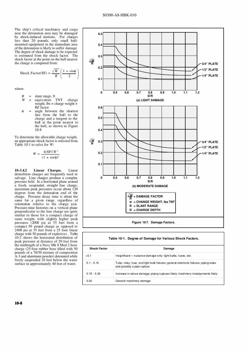
8132019 Articol despre explozii submarine
httpslidepdfcomreaderfullarticol-despre-explozii-submarine 824
S0300-A8-HBK-010
The shiprsquos critical machinery and cargo
Figure 10-7 Damage Factors
DR
DR
(b) MODERATE DAMAGE
(a) LIGHT DAMAGE
34 PLATE
34 PLATE
12 PLATE
12 PLATE
14 PLATE
14 PLATE
0
0
01
01
02
02
03
03
W
W
R
R
04
04
05
05
06
05
05
06
06
07
07
08
08
09
09
10
10
11
11
12
12
= CHANGE WEIGHT lbs TNT
= SLANT RANGE
= CHARGE DEPTH
= DAMAGE FACTOR
w
R
D
WR
near the detonation area may be damagedby shock-induced motions For chargesless than 20 pounds only small hull-mounted equipment in the immediate areaof the detonation is likely to suffer damageThe degree of shock damage to be expectedis estimated from the shock factor Theshock factor at the point on the hull nearestthe charge is computed from
where
Shock Factor(SF) = W
R
1 + sinφ2
R = slant range ftW = equivalent TNT charge
weight lbs = charge weight times RE factor
φ = angle between the shortestline from the hull to thecharge and a tangent to the
hull at the point nearest tothe hull as shown in Figure10-8
To determine the allowable charge weightan appropriate shock factor is selected fromTable 10-1 to solve for W
10-342 Linear Charges Linear
W = 4(SF)2 R 2
(1 + sinφ)2
demolition charges are frequently used insalvage Line charges produce a complexpressure field In a horizontal plane arounda freely suspended straight line chargemaximum peak pressures occur about 120degrees from the detonation end of thecharge Pressure decay time is about thesame for a given range regardless of orientation relative to the charge axisPressure-time histories on a vertical planeperpendicular to the line charge are quitesimilar to those for a compact charge of same weight with slightly higher peak pressures (2000 psi at 35 feet from acompact 50 pound charge as opposed to2400 psi at 35 feet from a 25 foot linearcharge with 50 pounds of explosive) Table
Table 10-1 Degree of Damage for Various Shock Factors
Shock Factor Damage
lt01 Insignificant ndash nuisance damage only l ight bulbs fuses etc
01 - 015 Tube relay fuse and light bulb failures general electronic failures piping leaks
and possibly a pipe rupture
015 - 020 Increase in above damage piping ruptures likely machinery misalignments likely
020 General machinery damage
10-2 shows the horizontal distribution of peak pressure at distance of 20 feet from
the midlength of a Navy Mk 8 Mod 2 hosecharge (25-foot rubber hose filled with 50pounds of a 7030 mixture of compositionA-3 and aluminum powder) detonated whilefreely suspended 10 feet below the watersurface in approximately 40 feet of water
10-810-8
8132019 Articol despre explozii submarine
httpslidepdfcomreaderfullarticol-despre-explozii-submarine 924
S0300-A8-HBK-010
In An Exploratory Investigation of the
Figure 10-8 Geometry for Calculating Shock Factor
CHARGE
R
φ
Effects of Underwater Line Charges onShip Plating Naval Ship Research andDevelopment Center December 1967 JKFleming and RE Oliver report that thedeflection of hull plating between stiffenerscaused by Navy Mk 8 Mod 2 hose chargescan predicted approximately by
where R t W and σ are as previously
d = 37 a
Ro σ t
2WLRo
4 R2
o L 2
defined and
d = plating set deflection in L = charge length fta = e ff ec ti ve p la ti ng s iz e
(between stiffeners) in
Table 10-2 Pressure Distribution Around Mk 8 Mod 2 Hose Charge
Gage position (angle between line from gage to midlength
and charge axis with detonation end at 0 degrees)
Peak Pressure
psi20 1300
30 1500
40 1730
50 2100
60 2600
70 3300
80 3730
90 3900
100 4220
110 4620
120 5000
130 4000
140 3960
150 2390
160 2250
170 2400
180 3050
All pressures measured 20 feet from midlength of charge
For rectangular plates effective plating sizeis determined from
where
a = 116
90
1
x 2
1
y 2
x = plate width in y = plate length in
10-343 Multiple Charges Multiplecharges detonated simultaneously aretreated as a single large chargemdashthe totalweight of all charges in the array must beless than the maximum acceptable chargeweight determined as described inParagraph 10-341 for a single charge
For multiple charges detonated individuallywith delays between detonations themaximum acceptable single charge weightis determined Charge weights should be
Figure 10-9 Minimum Delay Between Detonations in Charge Array
CHARGE DEPTH FEET
55 LBS TNT
35 LBS TNT
20 LBS TNT
10 LBS TNT
5 LBS TNT D E
L A Y
T I M E
S
E C O N D S
0
05
10
15
20
25
30
10 20 30 40 50 60
one-third the single charge weight or less toprevent progressive hull damage Aminimum delay time between detonations isnecessary to allow the energy from theprevious detonation to dissipate so structureblast loading is not cumulative Minimumdelay times are taken from Figure 10-9
10-344 Ballasting Water-backed hullsare more resistant to shock damage thanair-backed hulls When internal waterdamage is not a problem and the ship can
contain the water spaces in the vicinity of explosive charges may be ballasted How-ever the first air-backed bulkhead exposedto the explosive loading can incur damageif it is in close proximity to the charge
It is not necessary to flood exactly to thewaterline to increase shock resistance butthere should be several feet of water in anyballasted space and six inches to one foot of air between the water surface and the nextdeck No reliable data are available forpredicting how much the charge weight maybe increased if the ship is ballasted A large bubble collapsing near the hull can cause considerable damage even to water-backed plating
10-10-
8132019 Articol despre explozii submarine
httpslidepdfcomreaderfullarticol-despre-explozii-submarine 1024
S0300-A8-HBK-010
10-35 Effects on Marine Life Environmental protection agencies may require salvors to estimate blast effects on local marine life Lethal
ranges may be specified that will limit charge weight
Lethal range seldom exceeds 650 feet and is estimated by
Table 10-3 Fish Kill Range Constants
Fish Weight Depth of Blast ft K
α
1 oz 10 328 0220
1 oz 50 385 0256
1 oz 200 475 0262
1 lb 10 174 0264
1 lb 50 235 0275
1 lb 200 272 0299
30 lbs 10 86 0284
30 lbs 50 131 0314
30 lbs 200 139 0342
H MAX = KW α
where
H MAX = maximum horizontal range of lethal overpressures
feet
K α = coefficients from Table 10-3
W = charge weight pounds
Although fish kill range can be estimated it is very difficult to keep
fish out of a specified area Bubble screens have been used with
some success
10-36 Safe Distances for Above-water Blasts The minimum
distances to protect personnel against shock wave and overpressure
are
SD = 300 W 13
Bare charges on or in ground
SD = 350 W 13
Charges in rock
where
SD = safe distance ft
W = charge weight lbs TNT = W times RE factor
Fragments and debris may be thrown greater distances and hazard personnel in the open The projectile hazard can be reduced by
bull Greater separation distances
bull Confinement of the explosion at the source
bull Barricades between personnel and the blast site
bull Evacuation of nonessential personnel
bull Overhead cover
10-1010-10
8132019 Articol despre explozii submarine
httpslidepdfcomreaderfullarticol-despre-explozii-submarine 1124
8132019 Articol despre explozii submarine
httpslidepdfcomreaderfullarticol-despre-explozii-submarine 1224
S0300-A8-HBK-010
10-41 Charge Weight Charge weight selection is based on two criteria
bull The charge must be large enough to perform the task
bull The charge must not be so large that it causes unacceptable damage to the casualty nearby structures or the environment
The minimum charge weight that will accomplish the task (in one shot) may be greater than the maximum charge weight what will not causedamage It is usually possible to perform the task in a series of steps each using charge weights smaller than the maximum acceptable weight
10-42 Underwater Blasting Water
Figure 10-11 Shared Charge Cutting Sequence
EXPLOSIVECHARGE
CONTAINER
LINER
CAVITY
SHAPEDCHARGE
(a)
S T A N D
- O F F
DETONA-TION WAVEAPPROACHESCAVITY LINER
(b)SHOCK WAVECOLLAPSESLINER INDUCINGJET FORMATION
(c)
CUTTING JETAPPROACHESTARGETSURFACE
(d) PLASTIC FLOW
IS INDUCED INTHE TARGETMATERIAL ANDTHE JET STARTSTO PENETRATE
(e)
JET PASSESTHROUGHTHE TARGET -CUT ISCOMPLETE
(f)
INITIATORpressure on the side of an object oppositethe explosive blast opposes the impact andexpansion of the explosive When the work involves moving large surface areasresistance to movement caused by waterpressure and hydrodynamic drag issignificant and explosive effectiveness isreduced For example it takes about onepound of explosive to break up and move acubic yard of rock in dry air Two to sixpounds of explosive per cubic yard arerequired to break and move the same rock underwater Explosive effectiveness is
further reduced as depth increases
Steel cutting by ribbon charges shapedcharges etc where little surface movementis required is not significantly affected byimmersion in water Shaped chargeeffectiveness is reduced if water cannot bedisplaced or evacuated from the cavity andstand-off (shaped charges are discussed inParagraph 10-421)
Most explosives detonate satisfactorilyunder water Some explosives containwater-soluble ingredients and aredesensitized with time when immersedunless sealed in waterproof containers
Certain explosives depend on dispersed microscopic air or gas bubbles for ease of initiation Immersion in deep water compresses the bubblesand renders them ineffective so they can be used only in shallow water or if specially formulated for deep water use Explosives dependingon dispersed bubbles for initiation include those based on or sensitized by nitroglycerine and nitroglycerol such as gelignites and blastinggelatins and those containing aqueous solutions of ammonium nitrate such as water gels and emulsions
Most military high explosives and commercial explosives based on PETN RDX and TNT can be used reliably in deep water because theyare not are not significantly water-soluble and do not depend on gas bubbles for initiation
Overlying water is an effective tamping agent but if the charge is not in intimate contact with the target the intervening water layer will largelynegate the tamping effect Even a thin water layer between the charge and target will dissipate some of the explosive energy before it reachesthe target The shock and compression waves pass through two media interfacesmdashexplosive to water and water to target energy is reflectedaway from the target at each interface If charges cannot be placed in intimate contact with the work additional tamping in the form of sandbags clay or soil should be used to overcome the dissipation of energy by the intervening water
Potential water tamping lends a slight theoretical advantage to blasting from the wet side of a hull but offsetting advantages accrue whenexplosives are placed in the dry
bull Explosives fuses and initiators are not subject to the desensitizing effects of water immersion or to disturbing forces of currentand surge
bull Charges can be placed more effectivelymdashit is easier to secure charges and intimate contact with the target surface can be attained
bull Charges and firing circuits can be inspected immediately before firing
bull There is greater control over the personnel placing explosives and their work can be monitored and inspected with less effort
Immersion time prior to firing should be minimized to reduce the desensitization of the explosives and the possibility that current or surge willdislodge charges or initiating circuits
10-1210-12
8132019 Articol despre explozii submarine
httpslidepdfcomreaderfullarticol-despre-explozii-submarine 1324
S0300-A8-HBK-010
10-43 Cutting and Fracturing Charges A principal use of explosives in salvage is cutting hull plating and structure in ships High-velocitybrisant explosives such as TNT and plastic explosives are best for cutting steel or aluminum Structural members are cut by a variety ocharges
bull Shaped charges ndash A lined or unlined cavity in the explosive produces a high-energy cutting jet
bull Fracturing charges ndash Specialized charge geometry causes convergence of strain waves in the target
bull Simple contact charges ndash Breakage is accomplished by the combined but uncoordinated effects of shock waves strain pulses angas expansion
Shaped and fracturing charges are far more efficient than contact charges and should be used when available and when suited to working conditions Because of their relatively small charge weights shaped and fracturing charges must be placed precisely and must be held in positioagainst current or surge to be effective If charges cannot be placed precisely better results may be obtained with less efficient contact charge
10-431 Shaped Charges A hollowed-
Figure 10-12 Typical Shaped Charges for Salvage Work
FLEXIBLE LINEARSHAPED CHARGE
BOX TYPELINEAR CHARGE
EXPLOSIVE
TARGET
CASE
METALLINER
ENCLOSED
STAND-OFFSPACE
CYLINDRICALCHARGE
EXPLOSIVECORE
DENSEFLEXIBLE
SHEATH
WOODENSPOOL
out or shaped charge detonated against ahard surface produces a crater that isapproximately a mirror image of the chargecavity The shaped charge is initiated at apoint behind the cavity the detonation waveexpands omnidirectionally from theinitiation point or axis Reaching the cavitythe detonation wave converges on a plane
(for linear charges) or axis (in cylindricalcharges) perpendicular to the target surfaceThe convergence of the shock waveconcentrates the explosive energy in a smallarea The resultant cratering is called the
Munro Effect If the charge is lined withmetal or other dense material the explosioncollapses the liner and carries it in the shock wave to the target surface as a slug (orblade) of metal and hot gas that acts as acutting jet The jet heats and erodes thetarget surface Shock-wave pressure and jeteffects combine to induce plastic flow in thetarget and cut through the material Figure10-11 illustrates the cutting sequence for alined shaped charge
For optimum effect shaped charges arepositioned at a stand-off distance from thetarget surface to allow the penetration jet toform completely before it reaches the targetsurface Optimum stand-off varies with thecavity angle and charge size stand-off isd et er m in ed f r om t ec hn ic al o rmanufacturerrsquos data for the charge used
Various-sized cylindrical shaped chargesare made for hole cutting Linear chargesare used for long cuts Linear charges areusually made in the form of a box with thecavity liner set across the inside of the boxas shown in Figure 10-12 Flexible linearshaped charges can conform to irregular
surfaces and cut lines Well-designedlinear cutting charges obtain good resultswith relatively small charge weightsIndividual charge weight and explosiversquosconsumption are based on data publishedfor the particular explosives used Data formilitary shaped charges is given in the Technical Manual for the Use of Explosives in Underwater Salvage (NAVSEA SW061-AA-MMA-010Typical manufacturerrsquos data for linear shaped charges are shown in Figure 10-13 (Page 10-14)
10-110-1
8132019 Articol despre explozii submarine
httpslidepdfcomreaderfullarticol-despre-explozii-submarine 1424
S0300-A8-HBK-010
Shaped charges can be improvised as
Figure 10-13 Typical Manufacturerrsquos Data for Linear Shaped Charges
STAND-OFF FOR OPTIMUM PERFORMANCE(RDX OR PETN EXPLOSIVE)
MINIMUM CUTTING PERFORMANCEAT OPTIMUM STAND-OFF
MINIMUM CUTTING PERFORMANCEAT OPTIMUM STAND-OFF
MINIMUM CUTTING PERFORMANCEAT OPTIMUM STAND-OFF
MINIMUM CUTTING PERFORMANCEAT OPTIMUM STAND-OFF
5
30 15
10
05
02
01
2010
JETCORDSTAND-OFFTARGET
05
02
01
05
0201
01
02
05
01
02
01
02
05
10
20
02
05
01
02
05
10
1 0
2 0
3 0
4 0
5 0
1 0 0
2 0 0
EXPLOSIVE CORELOAD GRAINSFOOT
EXPLOSIVE CORELOAD GRAINSFOOT
EXPLOSIVE CORELOAD GRAINSFOOT
EXPLOSIVE CORELOAD GRAINSFOOT
NOTE CUTS AT 7 AND 10 GRFTMADE AT ZERO STAND-OFF
EXPLOSIVE CORELOAD GRAINSFOOT
100
5
5
10
10
50 100 200 500 1000
20
20
50
50
100
100
200 500
200 500 1000 2000 5 0 0
S T A N D
- O F F I N C H E S
T H I C K
N E S S
C U T
I N
C H E S
T H I C K N E S S
C U T
I N
C H E S
T H I C K N E S S
C U T
I N
C H E S
T H I C K N E S S
C U T
I N
C H E S
1 0 0 0
2 0 0 0
A L U M
I N U M
S H E A
T H
C O P P
E R S H E A
T H
L E A D
S H E A
T H
C 1 0 1 8 S T E E
L T A R G
E T
COPPER-SHEATHEDJETCORD (RDX ORPETN EXPLOSIVE)
LEAD-SHEATHEDJETCORD (RDX ORPETN EXPLOSIVE)
2024-T351ALUMINUM
TARGET
C10118STEELTARGET
2024-T351ALUMINUM
TARGET
C10118STEELTARGET
ALUMINUM-SHEATHEDJETCORD (RDX
OR PETN EXPLOSIVE)
SILVER-SHEATHEDJETCORD
(DIPAMEXPLOSIVE)
CUT7075-T6
ALUMINUMTARGET
OPTIMUMSTAND-OFF
shown in Figure 10-14 When performance
data for a particular material is not
available cutting ability can be estimated
from the following
where
t = t o
ρρ
o
t = unknown cutting capacity
(thickness) in material of
density ρt o = known cutting capacity in
material of density ρo from
manufacturerrsquos data
Water in the stand-off and cavity prevents
the formation of the cutting jet Theenclosed stand-off of box-type shaped
charges excludes water but boxes can
withstand hydrostatic pressures only to
shallow depths that vary with the particular
unit For depths of 30 to 60 feet the stand-
off can be filled with closed-cell plastic
foam The foam inhibits jet formation
slightly so that performance is decreased
For deeper immersion the stand-off and
cavity must be constructed to withstand
hydrostatic pressure or made free flooding
and then evacuated with compressed air or
gas at depth For underwater use flexible
linear charges can be enclosed in flexibletubes filled with foam or evacuated by
compressed gas One manufacturer markets
a line of circular cutters prefabricated with
compressed gas fittings
10-432 Fracturing Charges A diamond-shaped sheet of plastic explosive laid on a steel plate and detonated simultaneously from two
opposite corners will fracture the metal along a line between the two uninitiated corners This effect is shown in Figure 10-15(a) The fracture
mechanism depends on the pressure rise as the shock waves from the two detonating points collide followed by the relaxation as the waves
pass through one another and the combined effect of two tension waves rebounding from the far side of the target This arrangement is a
diamond charge and is suitable for cutting bars and pipes but has limited application for plate cutting because the fracture extends only slightly
beyond the charge
The diamond charge principle was first applied to extended plate cutting in fracture tape Fracture tape shown in Figure 10-15(b) consists of
a series of diamond charges connected by continuous strips of explosive along the edges of the charges Fracture tape has seen only limiteduse because it was not manufactured in a flexible form The charge may fail to cut if bilateral asymmetry develops between the two initiation
trains Fracture tape can be improvised by cutting explosive sheet to the appropriate shape
Shock-wave refraction tape (SRT) is a recently developed explosive charge that works on the principle of shock-wave collision within metal
targets In this charge a continuous strip of explosive is molded to the back of an inert wave-shaping element as shown in Figure 10-15(c)
One manufacturer uses magnetic rubber as the wave-shaping element providing both flexibility as well as an attachment method (provided the
surfaces are clean and smooth) The performance of shock-wave refraction tape is comparable to that of shaped charges when cutting ordinary
steels very high strength fracture-resistant steels may not be cut as easily There is no cavity or stand-off to flood so SRT is more adaptable
to underwater use than linear shaped charges
10-1410-14
8132019 Articol despre explozii submarine
httpslidepdfcomreaderfullarticol-despre-explozii-submarine 1524
S0300-A8-HBK-010
Figure 10-14 Improvised Shaped Charges
SHEETEXPLOSIVE
STEEL ORALUMINUM
ANGLE
PLASTICEXPLOSIVE
PLASTICEXPLOSIVE
CONE
WINEBOTTLE
STICKS TAPEDTO SIDE ASSTAND-OFF
FUSE
CAP
S T A N D - O
F F
D I S T A N C E
FOOD CANWITH BOTHENDS CUT
OUTPLASTICEXPLOSIVE
SHEETMETALOR LEADSHEETCONE
RIVET
SIDES OFCAN FORMSTAND-OFF
CAP
80˚ - 90˚
Figure 10-15 Fracturing Charges
A
Arsquo
A ArsquoEXPLOSIVE
FRACTURE
EXPLOSIVESHOCK-WAVEFRONTS
REFLECTEDTENSION WAVE
(a) DIAMOND CHARGE (INITIATED AT POINTS A AND Arsquo)
(c) SHOCK-WAVE REFRACTION TAPE (SRT)(b) FRACTURE TAPE
EXPLOSIVE
INERT BARRIERSINITIATION POINT
EXPLOSIVE
WAVE-SHAPINGELEMENT
FRACTURES TENSIONWAVE
SHOCK WAVE
10-110-1
8132019 Articol despre explozii submarine
httpslidepdfcomreaderfullarticol-despre-explozii-submarine 1624
S0300-A8-HBK-010
10-433 Contact Charges Simple
Figure 10-16 Steel Cutting Contact Charges
DETONATINGCORD
EXPLOSIVE
STEEL PLATE
WELDS
STEELCHANNEL
STUD
PLATE
SECURINGSTRAP
EXPLOSIVESHEET OR
PLASTICEXPLOSIVE
contact charges require much heaviercharges than shaped or fracturing chargesExplosive performance can be increasedand charge weight reduced by carefulcharge placement confinement tampingand by scoring cut lines with cuttingtorches or mechanical cutters Some
effective charge placements and geometryare shown in Figure 10-16
Charge weights can be estimated from thefollowing relationships
where
W = 3
8 A Structural steel
W = D 2 High carbon or alloy steel
W = charge weight lbs TNT
A = cross-sectional area of sectionto be cut in2
D = diameter or thickness of section to be cut in
To determine charge weights for explosivesother than TNT the TNT charge weight isdivided by the relative effectiveness (RE)factor
10-434 Charge Placement Cutting charges are most effective when the cut line is adjacent to but not on a rigid portion of the target surfaceThe target must be restrained from moving away from shaped and fracturing charges so the explosive energy is expended in cutting or fracturingthe target rather than pushing it away Contact charges create a strong shearing action along the line between the movable and rigid surfaceHull cutting charges are most effective when slightly offset from frames
bull If placed in the middle of the span a large portion of the explosive energy is expended in deflecting the plate
bull If placed directly over a stiffener both the stiffener and the plate must be cut
For efficient cutting charges must be placed in intimate contact with the target surface Charges must be secured to all vertical steeply angledand overhead surfaces and to horizontal surfaces where current wind vibration or target movement may dislodge them Where no tie-downpoints exist the following securing methods can be used
bull Light metal straps bolted to studs explosively set or friction welded along each side of the cut line
bull Tie-down wires lines or bongee cords inserted through holes cut drilled or burned through the plating (tie-downs can also beled to studs or magnetic clamps)
bull Sandbags or similar weights placed on charges on horizontal surfaces
bull Backing charges with magnetic strips adhesive strips or small suction pads (these methods have had limited success)
bull Hose charges can be stretched between tie-down points over flat or smoothly convex surfaces
10-435 Ship Sectioning Explosives are commonly used to section wrecks for piecemeal removal or to separate a casualty into two piecesso that one part can be salvaged Ship sectioning including explosive methods is discussed in the US Navy Ship Salvage Manual Volume 2(S0300-A6-MAN-020) The following notes supplement that discussion
10-1610-16
8132019 Articol despre explozii submarine
httpslidepdfcomreaderfullarticol-despre-explozii-submarine 1724
S0300-A8-HBK-010
When cutting a ship transversely the internal structure must be cut as well as the more accessible hull plate and stiffeners It is very difficu
to obtain complete separation in a single shot Salvors should plan to make cuts in several shots or have thermal or mechanical cutting gea
available to sever stubborn structure
In a landmark operation in 1973 the salvageable aft section of a 960-foot laden ore carrier was explosively separated from the forward part o
the ship which was abandoned The ship had sunk by the bow in 130 feet of water With holds 7 8 9 and 10 their associated wing and
double-bottom tanks and the machinery spaces dry the after section was buoyant and afloat The hull was cut in way of number 7 hold b
more than 1800 feet of custom engineered and fabricated high speed explosive cutters All cutters were placed in the dry number 7 wing anbottom tanks Instantaneous separation (necessary to prevent capsize of or damage to the aft section) was attained by
bull Placing cutters against all bulkheads shell plating stringers void tank sections and pipes extending through the transvers
bulkhead separating holds 7 and 8
bull Taking advantage of the vertical shear on the hull resulting from the weight of the forward section laden with 90000 tons of ore
and the buoyancy of the after section and
bull Maintaining a 300-ton horizontal astern pull on the after section as the cutters were detonated
Blast curtains were rigged in the number 7 tanks and hold and the number 8 wing and bottom tanks were pressurized with compressed air to
protect the separating bulkhead A diverrsquos survey after the successful separation revealed no damage to the bulkhead The operation was mad
possible by the salvorsrsquo employment of specialist explosives engineers who custom designed the explosive cutters taking into account permissiblblast effects on the aft number 7 bulkhead gas generation and dispersion requirements mutual interference between charges and the strength
of hull structural members See The Cutting of the Igara in Reedrsquos Commercial Salvage Practice for a more detailed discussion of th
operation
The order in which the different members are to be cutmdashas well as the methods to be usedmdashmust be considered carefully Preliminary cut
should not weaken the structure to the point that it is in danger of collapsing and injuring personnel placing charges for subsequent cuts
Cutting methods are frequently combined A hull can be opened up with explosives to permit access to internal structure to be cut by mechanica
or thermal methods In some cases preparatory weakening cuts are made by divers with oxy-arc or exothermic torches with the final cuts mad
explosively
Simple types of ships are better candidates for explosive sectioning than more complex types The following ship types lend themselves t
explosive sectioning
bull Transversely framed ships because there are fewer longitudinal stiffeners to cut
bull Freighters and bulk carriers because most do not have centerline longitudinal bulkheads (some bulk carriers have wing tanks whos
inner bulkheads must be cut) Small ships often do not have double bottoms
bull Small single-product tankers because they do not have wing tanks or double bottoms
The following ship types are not good candidates for explosive sectioning
bull Longitudinally framed ships because of the large number of longitudinal stiffeners
bull Passenger ships and warships because of their extensive joiner work internal subdivision wireways piping and ventilatio
systems
bull Large tankers and product carriers because they are constructed with two or more longitudinal bulkheads
bull Freighters with insulated holds
10-110-1
8132019 Articol despre explozii submarine
httpslidepdfcomreaderfullarticol-despre-explozii-submarine 1824
S0300-A8-HBK-010
10-44 Seafloor Blasting Seafloor
Figure 10-17 Obstruction Blasting
CONTACT BLASTING MUDCAPPING
SNAKEHOLING
STEMMINGSTEMMING
CHARGE
CHARGE
BLOCKHOLING
blasting moves large amounts of seafloor
material by channeling trenching etc or
removes isolated obstructions such as
pinnacles coral heads and boulders The
basic techniques are
bull Contact Blasting ndash Chargesare placed on the formation
to be blasted either indi-
vidually or in line or
checkerboard patterns The
detonating explosive imparts
a violent blow to the seafloor
material The efficiency of
contact blasting depends on
maintaining intimate contact
with the material to be
blasted Contact blasting is
the least efficient blasting
method in terms of explosive
consumption but requires the
least time and effort to
prepare and set charges
bull Boreholes ndash Internal charges
are placed in boreholes
drilled or augured into the
object or strata to be blasted
10-441 Rock Blasting The choice of explosive for a particular rock-blasting job depends on the hardness and density of the rock and the
type of breakage desired Fast brisant explosives such as TNT or composition C-4 are required to break most kinds of rock although slower
explosives are effective on soft rock such as limestone
Rock is weakest in tension so internal charges are most effective Contact blasting depends on the tamping effect of overlying water to confine
the explosion momentarily and is effective only on soft rock and coral where the material is broken by crushing rather than shattering The
rock fragments are moved by the expanding gases so high gas production is required to move dense rock If the object is to break up rock for
removal by nonexplosive means gas production of the explosive is less important Individual boulders are broken by one of the methods
discussed below The methods are illustrated in Figure 10-17
bull Mudcapping ndash A contact charge is covered with 10 to 12 inches of mud clay or moist soil tamping Plastic clay is the most
effective tamping Loose sand should not be used but sandbags are effective
bull Snakeholing ndash The charge is placed in a hole jetted bored or otherwise excavated under an object lying on or partially buried
in a soft seafloor Snakeholing is more effective than mudcapping under all conditions and requires about one-half as much
explosive as contact blasting
bull Blockholing ndash The charge or charges are placed in one or more boreholes Explosive effect can be altered by changing charge
weights and placement rock formations boulders concrete structures etc can be completely demolished be broken into
fragments of varying size or have portions broken off Blockholing requires about one-third as much explosive as contact blasting
Table 10-4 gives approximate explosive requirements in pounds per
Table 10-4 Powder Factors (lbyd3) for Rock Blasting
Blas ting Metho d A ir B la sting Und erwater Blas ting
Contact Blasting Not effective 6 - 20
Mudcapping 1 - 2 4 - 15
Snakeholing 1 - 11 frasl 2 3 - 10
cubic yard or powder factor for different rock-blasting methods A
range of powder factors for each method is given The actual powder
factor for any project will depend on
bull The relative density and toughness of the rock
bull Whether individual boulders or massive rock formations
are being blasted
bull Water depth
10-1810-18
8132019 Articol despre explozii submarine
httpslidepdfcomreaderfullarticol-despre-explozii-submarine 1924
S0300-A8-HBK-010
The lower values in Table 10-4 are based
Table 10-5 Rock Density and Toughness
Type of Rock Density lbft3 Relative Toughness (Limestone = 1)
Andesite 150 - 175 11
Basalt 150 - 200 17 - 23
Conglomerate 125 - 162 NA
Dioritic 156 - 200 19 - 21
Felsite 150 - 200 NA
Gabbro 169 - 200 NA
Granite 156 - 194 15 - 21
Gneiss 150 - 181 10 - 19
Limestone 160 - 187 10
Marble 131 - 181 NA
Quartzite 125 - 200 19 - 27
Sandstone 124 - 194 15 - 26
Schist 150 - 175 10 - 21
Shale 112 - 194 NA
Slate 156 - 194 12
on blasting massive limestone at depths of 30 to 60 feet Values high in the range areused with tougher or denser rocks andgreater depth Lower values are used whenblasting individual boulders or outcrop-pings Table 10-5 compares densities andtoughness of common rocks
Rock blasting by internal charges is mosteffective when there is a free face approxi-mately parallel to the borehole Thedetonation of the explosive creates a highgas pressure in the charge hole generating acompressive strain pulse in the surroundingrock The compressive pulse travels outwardin all directions Near the hole theamplitude of the strain pulse is sufficient tocrush the rock Amplitude decays rapidly asthe pulse travels outward until it can nolonger crush the rock The pulse travels out-ward until it is reflected from a free surfaceas a tensile strain pulse As rock is much
Figure 10-18 Excavation Rock Blasting
DRILLING FACE
WORKING OR FREE FACE
BOREHOLE
BENCH
EXCAVATION FLOOR(PROJECT DEPTH)
L
B
BltL
INSUFFICIENT EXPLOSIVEENERGY RELEASE AT
BOTTOM OF HOLE
B
MAINFRACTURELINES
COLUMN LOADEDHOLE
45˚
STRESS PATTERN FOR ACONCENTRATED CHARGE
IN BOTTOM OF HOLE
REFLECTEDTENSION WAVE
UNREFLECTEDCOMPRESSIONWAVE
TOE
weaker in tension than compression the
tensile pulse is able to break the rock pro-gressing from the free face back towards thecharge hole The expanding gases in thecharge hole are not directly responsible formuch of the rock breakage to some extentthe rock is pulled apart rather than pushedapart
Blasting massive seafloor rock formations issubject to constraints similar to those en-countered in quarry blasting and similarmethods are employed Detailed informationon rock blasting is found in publications onmining and quarrying For effective blastingit is necessary to establish a breaking orworking face at an angle to the drilling faceThe drilling face is most often the horizontalseafloor the working face is vertical orinclined from the vertical by an angle of 45degrees or less The working face is brokenback in steps by detonating charges in rowsof holes behind the face For cuts deeperthan the maximum practical drilling depththe working face is broken back in stages byestablishing intermediate floor levels orbenches as shown in Figure 10-18
A working face can be established in aflush surface by blasting out a crater with asingle charged hole cluster of holes or lineof holes Empty relief holes between andaround charged holes provide free faces toreflect strain pulses and space for displaced
rock to move into The excavation floorand work face can be squared up bysubsequent blasting
Boreholes can be drilled by diver-operated jackhammers or rock drills for smalloperations For extensive drillingoperations a spud-moored drill barge or asubmersible crawler-mounted rock drillshould be used
10-110-1
8132019 Articol despre explozii submarine
httpslidepdfcomreaderfullarticol-despre-explozii-submarine 2024
S0300-A8-HBK-010
10-442 Coral Blasting Coral is difficult
Figure 10-19 Coral Blasting
13
13
12
12
11
11
10
10
9
9
8
8
7
7
6
6
5
5
4
4
3
3
2
2
1
1
0
0
DEPTH AND WIDTH OF CUTS MADE IN CORAL WHEN BLASTING WITH CAVITY CHARGES
DEPTH AND WIDTH OF CUTS MADE IN CORAL BY STANDARDUS MARK 8 DEMOLITION CHARGES
VOLUME OF CORAL REMOVED USING9-KG (20 POUND) CHARGES
CRATER WIDTH IN FEET
CRATER WIDTH IN FEET
NUMBER OF PACKS
V O L U M E
I N
C U B I C
F E E T
1 2 3 4 5
1
1
2
2
3
3
4
4
5
5
6
6
7
7
8
8
9
9
10
10
11
11
12
12
13
13
1
1
2
2
3
3
4
4
5
5
100
20
30
40
50
60
70
80
90
100110
D E P T H
I N
F E E T
D E P T H
I N
F E E T
to blast because of its porosity High-velocity explosives have been successfulbut slow-detonating explosives are moreeffective Coral will clog rock drills sointernal charges are set in powder points(pipes driven into the formation) Powderfactors for coral are about five pounds per
cubic foot for mushroom-shaped coralheads and higher for solid headsDemolition of an above-water coralformation requires about three times asmuch explosive as an equivalent underwaterformation unless a well-placed thoroughlytamped internal charge is used Linecharges can be used to cut trenches orchannels in coral Figure 10-19 showstypical results of coral blasting
10-443 Blasting ImpalementsRemoving an impaling rock or coral head isa slow and tedious process The chargesmust be large enough to break the rock orcoral but light enough that they do not
damage the ship or drive the impalementfurther into the ship The only feasibleprocedure is to begin with very smallcharges and check the results after eachshot Charge size can be increasedincrementally if there is no hull damage orthe same charge can be repeated until theimpalement is gradually severed or brokenaway A large internal concrete patch overthe impalement and surrounding platingstrengthens the hull against shock loadingso that larger charges can be used Theimpalement should be cut off about twofeet below the hull
When external access to the impalement isdangerous or impossible the impalement isattacked from the inside The bestprocedure is to use small charges inshallow boreholes with interspersed relief holes to progressively shatter theimpalement and lower it sufficiently toclear the hull Doors and hatches should beopen during blasting to prevent the hull from being pressurized internally by the explosive gases It may be necessary to build a trunk aroundthe impalement to provide a watertight enclosure and to vent explosive gases to the atmosphere
10-444 Setting Anchors Anchors can be set in hard pan coral clay or mud bottoms with explosives Small charges are set near the anchoras shown in Figure 10-20 and detonated The anchor is lifted and dropped into the blast crater At the same time a quantity of loose or brokenseafloor is lifted out of the crater and some of this material will settle on the anchor Anchors can be explosively settled into seafloors subjectto liquefication under high-frequency cyclic loading such as clean medium- or low-density cohesionless soils A number of small chargesdetonated sequentially on short delay in the vicinity of the anchor can liquefy the soil allowing the anchor to settle into the seafloor underits own weight
10-445 Channeling in Soft Bottoms Military dynamite or other low-velocity low-brisance explosives are best for moving soft plasticmaterial Powder points contact charges charges in augured or excavated holes or hose charges in checkerboard or linear patterns are usedContact blasting will normally dig a channel or crater four to five feet deep Deeper cuts can be attained by driving powder points to the desiredchannel depth plus the distance between points Powder factors are three to five pounds of explosive per cubic yard of soil Alternate pointsshould contain charges of different weights so that the detonation waves do not cancel one another Soft seafloors are almost always excavatedmore effectively by nonexplosive means such as dredging or scouring
10-2010-20
8132019 Articol despre explozii submarine
httpslidepdfcomreaderfullarticol-despre-explozii-submarine 2124
S0300-A8-HBK-010
10-45 Concrete and Masonry Blasting
Figure 10-20 Setting Anchors with Explosive Charges
CHARGESANCHOR
FIRING SYSTEM BLASTING CAP
BUOY
DETONATING CORD MADEUP TO WORKING LINE
LIGHT LINE TO KEEP STRAINOFF DETONATING CORD
Concrete and masonry are blasted by thesame methods as rock Simple concretedispersal requires about one pound of explosive per cubic foot Breachingcharges for concrete and masonry structuresare estimated by
W = R
3
KC where
W = charge weight lbs TNT R = breaking radius ft
= thickness for externalcharges
= distance to outside surfacefor internal charges
K = material factor from Table10-6
C = tamping factor from Figure10-21 (Page 10-22)
10-46 Timber and Pile Cutting Forcutting timber high-velocity brisant
explosives work best but low-velocityexplosives are effective when appliedproperly Charge weights vary as thesquare of the diameter of the timberEmpirical relationships for determiningcharge weights are given below
where
W = D 2
4Untamped external charges
W = D 2
250Tamped internal charges
Table 10-6 Material Factor K for Concrete Breaching Charges
Material R K
Poor masonry shale and hardpan All values 0225
Good masonry ordinary concrete rock
Less than 3 ft
3 to 5 ft
5 to 7 ft
More than 7 ft
035
0275
025
0225
Dense concrete first-class masonry
Less than 3 ft
3 to 5 ft
5 to 7 ft
More than 7 ft
045
0375
0325
0275
Reinforced concrete (concrete only will
not cut reinforcing steel)
Less than 3 ft
3 to 5 ft
5 to 7 ft
More than 7 ft
070
055
050
0425
W = charge weight lbs TNT D = diameter of round or leastdimension of dressedtimber in
For explosives other than TNT chargeweight is determined by dividing the TNTcharge weight by the relative effectiveness(RE) factor
10-47 Reducing Underwater ShockWave Pressure and Impulse Shock waves damage structures by two differentmechanisms
bull The peak shock wave pressureexceeds the compressive strengthof the material
bull The impulse causes structural elements to vibrate with their natural frequency The deflection may be great enough to cause damageImpulse caused vibrations can cause damage even when the peak pressure does not exceed the compressive strength of the material
Shock wave pressure or impulse at a structure can be reduced by charge placement bubble screens and in the case of multiple charges firingsequence
10-210-2
8132019 Articol despre explozii submarine
httpslidepdfcomreaderfullarticol-despre-explozii-submarine 2224
S0300-A8-HBK-010
10-471 Charge Placement Observations
Figure 10-21 Tamping Factor C for Concrete Breaching Charges
C = 45
C = 25 C = 20 - 25
C = 23C = 35
C = 20 C = 15
C = 25
UNTAMPED CHARGES
TAMPED CHARGES
R
R R
R
R
R R
R
t 03tltdltt
D
C = 125C = 125
STEMMED PLACED IN
CENTER OFMASS
C = 125 - 10
R
t dgtt
DR
R
FILL
Figure 10-22 Shock Wave Effects for Various Blasting Conditions
NOTE
620PSI
50PSI
29PSI
14 MS
13 MS
2 MS
(a) 33 FT FROM 1LB CHARGEIN FREE WATER
EXTRAPOLATED FROM DATAFOR POINT 47 FT FROM 3LBCHARGE IN FREE WATER
NOTEEXTRAPOLATED FROM DATAFOR POINT 47 FT FROM 2LBCHARGE IN 29 FT3 OF ROCK
(b) 33 FT FROM 1LBCHARGE IN ROCK
(c) 33 FT FROM 1LB CHARGEIN FREE WATER THROUGHBUBBLE SCREEN(0043 FT3SEC PER FT)
of underwater rock blasting operations haveshown that peak pressures for explosiveswell packed in bore holes is much less thanthat of charges in the water Figure 10-22compares time pressure curves 33 feet froma one pound charge in free water and thesame sized charge in submerged rock Thegreat difference in peak pressures and totalimpulse indicates that a principal means of reducing underwater shock wave effects isto ensure that charges are not detonated whileexposed to free water In seafloor orobstruction blasting internal charges shouldbe used The top portions of boreholes fora distance of 15 times the borehole diametershould be left uncharged Blasting patternsshould be arranged to avoid sympatheticdetonation and ensure that charges to bedetonated later in a firing sequence are notexposed by rock breakage from earlierdetonations Heavy sandbag or clay tampingover cutting charges can significantly reduceshock effects in the surrounding area
10-472 Bubble Screens An impingingshock wave compresses the bubbles of abubble screen over a period of somemilliseconds On their subsequent re-expansion over a period of milliseconds thebubbles emit new compression waves withlower peak values The part of the shock wave that passes between the bubbles isalso attenuated Increasing the number of air bubbles increases the reduction in peak pressure but also increases the duration of the pressure on the side of the bubblescreen away from the blast Investigationsby AT Edwards at the Hydro-electricPower Commission of Ontario showed thatthe peak pressure 33 feet from a one poundcharge was reduced by a factor of 10 by anintervening bubble screen produced by anair flow of 0043 cubic feet per second perfoot of pipe Doubling the air flow reducedpeak pressure by a factor of 70 at the samedistance with the same charge weight At164 feet the corresponding reductionfactors were 8 and 40 Three inchdiameter pipe was used in the experimentswith groups of two diametrically opposite1 frasl 16-inch holes spaced 3 frasl 4-inch or 11 frasl 2 inchesapart Figure 10-22 shows the pressure-time history 33 feet from a one poundcharge with an intervening water curtain
In reducing peak pressure while simultan-eously extending the decay time the bubble
screen redistributes but does not decrease to-tal impulse Bubbles screens are ineffectivein preventing damage in most cases wherethe damage mechanism is primarily impulse
10-473 Firing Sequence In multiple-charge shot-delay shots firing the chargesclosest to the structure to be shielded firstwill reduce the impulse transmitted to thestructure by the delayed charges Theimpulse from the delayed charges is partlyscreened off by explosion gases (and brokenrock when seafloor blasting) from earliercharges
10-2210-22
8132019 Articol despre explozii submarine
httpslidepdfcomreaderfullarticol-despre-explozii-submarine 2324
S0300-A8-HBK-010
10-5 PERMITS
Authorization from the appropriate fleet commander is required for all underwater explosives detonations OPNAVINST 85302 lists the basi
requirements to be met before using demolitions Amplifying instructions in the 8530 series have been issued by fleet commanders
Some of the additional permits required from various Federal and local agencies are described in the following paragraphs It may take man
months to obtain all the required permits Planning for explosives operations should start well in advance and be coordinated carefully so thaall permits are valid over the desired time frame and that other salvage tasks that proceed sequentially or concurrently with the explosive
operations are ready on schedule
10-51 Corps of Engineers Section 10 of the River and Harbor Act of March 3 1899 (30 Stat 1151 33 USC 403) prohibits the obstructio
or alteration of any navigable water of the United States without authorization from the Secretary of the Army Requirements for and limitation
of permits are described in Title 33 of the US Code of Federal Regulations (33 CFR) Article 209120 Detailed information concerning th
permits required for a specific project can be obtained from the local Corps of Engineers Office or from the Department of the Army Offic
of the Chief of Engineers Washington DC 20314
10-52 Environmental Impact Statement Explosives projects that may have an adverse effect on the environment may require the filing o
an Environmental Impact Statement Information on the filing of the statement is found in OPNAVINST 50901 (series)
10-53 State and Local Agencies The number and kind of permits required for explosives operations varies widely from location to location
A partial listing of agencies that may require permits includes
bull State Fish and Game Commission
bull State Lands Commission
bull State Oil and Gas Commission
bull StateEnvironmental Commission Department of Environmental ManagementEnvironmental Protection Agency or similar agency
bull County Board of Supervisors
bull Local police or sheriff
bull Fire Marshal
bull City Engineer
10-6 OPERATIONAL NOTES
10-61 Test Shots Because of the imprecise nature of charge weight and blast effect calculations test shots should always be made before
or at the beginning of an explosives job Test shots are made to determine two quantities
bull The minimum charge weight required to perform the task
bull The maximum charge weight that will not cause unacceptable damage to the casualty nearby structures or the environment
Tests to determine minimum charge weight should be conducted well before the operation at an explosives range or remote site
The maximum acceptable charge weight is estimated by calculation and verified by on-site test shots Test shots are usually conducted as th
first working shots Test shots start with charges lighter than those calculated for the job gradually increasing the charge weights until th
minimum charge weight to perform the task is reached or blast effects become unacceptable
10-210-2
8132019 Articol despre explozii submarine
httpslidepdfcomreaderfullarticol-despre-explozii-submarine 2424
S0300-A8-HBK-010
10-62 Explosives Expertise The importance of seeking the advice of experienced hands for explosives projects cannot be overemphasized
There is no program in the US Navy to train or certify salvage demolitions specialists Navy first class divers and diving officers receive
limited explosives demolitions training Explosive ordnance disposal (EOD) divers and special warfare swimmers (SEAL) receive additional
training in specialized procedures that are not always applicable to salvage The particular demolitions expertise of a Navy diver is a function
of on-the-job experience that may vary from extensive to none In the absence of personnel experienced in salvage demolitions advice may
be sought from Navy Mobile Construction Battalions or the Army Corps of Engineers Commercial explosives consultants may be retained
through the Supervisor of Salvage
10-63 US Military Explosives A wide variety of explosives in various types of demolition charges are maintained in the system for use
by military forces These explosives and charges are described in the Navy technical manuals Use of Explosives in Underwater Salvage
(NAVSEA-SW061-AA-MMA-010) and Demolition Materials (NAVSEA OP 2212) and the Army field manual Explosives and Demolitions (FM
5-25) A summary of the characteristics of US Military explosives is given in Table 10-7
Table 10-7 Characteristics of Military Explosives
Explosive Typical Uses
Rate of Detonation
(Feet per Second)
Relative Effectiveness as
an External Charge
(TNT = 100)
Intensity of
Toxic Fumes
Water
Resistance
Amatol Bursting Charge 16000 fps 117 Dangerous Poor
Ammonium Nitrate Cratering Charge and
Composition Explosives 8900 fps 042 Dangerous None
Black Powder Time Blasting Fuse 1300 fps 055 Dangerous None
Composition A-3 Booster Charge and Bursting
Charge 26500 fps 126 Dangerous Good
Composition B Bursting Charge 25600 fps 135 Dangerous Excellent
Composition C-3 Demolition Charge 25000 fps 126 Dangerous Good
Composition C-4 Demolition Charge 26500 fps 126 Dangerous Excellent
HBX-1 and HBX-3 Demolition Charge 24300 fps Air 148
Underwater 168 Dangerous Excellent
H-6 Demolition Charge 24300 fps Air 148
Underwater 168 Dangerous Excellent
Pentolite 5050
Booster Charge and Bursting
Charge 24600 fps 126 Dangerous Excellent
PETN Detonating Cord Blasting Cap
and Demolition Charge 26000 fps 166 Dangerous Excellent
RDX Blasting Caps Composition
Explosives 27400 fps 160 Dangerous Excellent
Tetryl Booster Charge and
Composition Explosives 23300 fps 125 Dangerous Excellent
Tetrytol 7525 Demolition Charge 23000 fps 120 Dangerous Excellent
TNT Demolition Charge and
Composition Explosives 22500 fps 100 Dangerous Excellent
TNT is used as the standard (TNT = 100) for comparison of the effectiveness of other explosives
10-64 Commercial Explosives A variety of commercial explosives and explosive devices are available including highly effective custom-
made steel cutting charges liquid explosives gelatins etc The Supervisor of Salvage should be contacted if the use of commercial explosives
is indicated
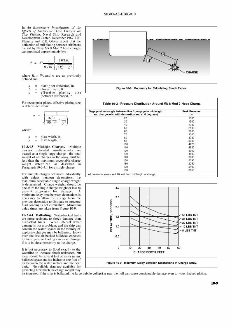
8132019 Articol despre explozii submarine
httpslidepdfcomreaderfullarticol-despre-explozii-submarine 924
S0300-A8-HBK-010
In An Exploratory Investigation of the
Figure 10-8 Geometry for Calculating Shock Factor
CHARGE
R
φ
Effects of Underwater Line Charges onShip Plating Naval Ship Research andDevelopment Center December 1967 JKFleming and RE Oliver report that thedeflection of hull plating between stiffenerscaused by Navy Mk 8 Mod 2 hose chargescan predicted approximately by
where R t W and σ are as previously
d = 37 a
Ro σ t
2WLRo
4 R2
o L 2
defined and
d = plating set deflection in L = charge length fta = e ff ec ti ve p la ti ng s iz e
(between stiffeners) in
Table 10-2 Pressure Distribution Around Mk 8 Mod 2 Hose Charge
Gage position (angle between line from gage to midlength
and charge axis with detonation end at 0 degrees)
Peak Pressure
psi20 1300
30 1500
40 1730
50 2100
60 2600
70 3300
80 3730
90 3900
100 4220
110 4620
120 5000
130 4000
140 3960
150 2390
160 2250
170 2400
180 3050
All pressures measured 20 feet from midlength of charge
For rectangular plates effective plating sizeis determined from
where
a = 116
90
1
x 2
1
y 2
x = plate width in y = plate length in
10-343 Multiple Charges Multiplecharges detonated simultaneously aretreated as a single large chargemdashthe totalweight of all charges in the array must beless than the maximum acceptable chargeweight determined as described inParagraph 10-341 for a single charge
For multiple charges detonated individuallywith delays between detonations themaximum acceptable single charge weightis determined Charge weights should be
Figure 10-9 Minimum Delay Between Detonations in Charge Array
CHARGE DEPTH FEET
55 LBS TNT
35 LBS TNT
20 LBS TNT
10 LBS TNT
5 LBS TNT D E
L A Y
T I M E
S
E C O N D S
0
05
10
15
20
25
30
10 20 30 40 50 60
one-third the single charge weight or less toprevent progressive hull damage Aminimum delay time between detonations isnecessary to allow the energy from theprevious detonation to dissipate so structureblast loading is not cumulative Minimumdelay times are taken from Figure 10-9
10-344 Ballasting Water-backed hullsare more resistant to shock damage thanair-backed hulls When internal waterdamage is not a problem and the ship can
contain the water spaces in the vicinity of explosive charges may be ballasted How-ever the first air-backed bulkhead exposedto the explosive loading can incur damageif it is in close proximity to the charge
It is not necessary to flood exactly to thewaterline to increase shock resistance butthere should be several feet of water in anyballasted space and six inches to one foot of air between the water surface and the nextdeck No reliable data are available forpredicting how much the charge weight maybe increased if the ship is ballasted A large bubble collapsing near the hull can cause considerable damage even to water-backed plating
10-10-
8132019 Articol despre explozii submarine
httpslidepdfcomreaderfullarticol-despre-explozii-submarine 1024
S0300-A8-HBK-010
10-35 Effects on Marine Life Environmental protection agencies may require salvors to estimate blast effects on local marine life Lethal
ranges may be specified that will limit charge weight
Lethal range seldom exceeds 650 feet and is estimated by
Table 10-3 Fish Kill Range Constants
Fish Weight Depth of Blast ft K
α
1 oz 10 328 0220
1 oz 50 385 0256
1 oz 200 475 0262
1 lb 10 174 0264
1 lb 50 235 0275
1 lb 200 272 0299
30 lbs 10 86 0284
30 lbs 50 131 0314
30 lbs 200 139 0342
H MAX = KW α
where
H MAX = maximum horizontal range of lethal overpressures
feet
K α = coefficients from Table 10-3
W = charge weight pounds
Although fish kill range can be estimated it is very difficult to keep
fish out of a specified area Bubble screens have been used with
some success
10-36 Safe Distances for Above-water Blasts The minimum
distances to protect personnel against shock wave and overpressure
are
SD = 300 W 13
Bare charges on or in ground
SD = 350 W 13
Charges in rock
where
SD = safe distance ft
W = charge weight lbs TNT = W times RE factor
Fragments and debris may be thrown greater distances and hazard personnel in the open The projectile hazard can be reduced by
bull Greater separation distances
bull Confinement of the explosion at the source
bull Barricades between personnel and the blast site
bull Evacuation of nonessential personnel
bull Overhead cover
10-1010-10
8132019 Articol despre explozii submarine
httpslidepdfcomreaderfullarticol-despre-explozii-submarine 1124
8132019 Articol despre explozii submarine
httpslidepdfcomreaderfullarticol-despre-explozii-submarine 1224
S0300-A8-HBK-010
10-41 Charge Weight Charge weight selection is based on two criteria
bull The charge must be large enough to perform the task
bull The charge must not be so large that it causes unacceptable damage to the casualty nearby structures or the environment
The minimum charge weight that will accomplish the task (in one shot) may be greater than the maximum charge weight what will not causedamage It is usually possible to perform the task in a series of steps each using charge weights smaller than the maximum acceptable weight
10-42 Underwater Blasting Water
Figure 10-11 Shared Charge Cutting Sequence
EXPLOSIVECHARGE
CONTAINER
LINER
CAVITY
SHAPEDCHARGE
(a)
S T A N D
- O F F
DETONA-TION WAVEAPPROACHESCAVITY LINER
(b)SHOCK WAVECOLLAPSESLINER INDUCINGJET FORMATION
(c)
CUTTING JETAPPROACHESTARGETSURFACE
(d) PLASTIC FLOW
IS INDUCED INTHE TARGETMATERIAL ANDTHE JET STARTSTO PENETRATE
(e)
JET PASSESTHROUGHTHE TARGET -CUT ISCOMPLETE
(f)
INITIATORpressure on the side of an object oppositethe explosive blast opposes the impact andexpansion of the explosive When the work involves moving large surface areasresistance to movement caused by waterpressure and hydrodynamic drag issignificant and explosive effectiveness isreduced For example it takes about onepound of explosive to break up and move acubic yard of rock in dry air Two to sixpounds of explosive per cubic yard arerequired to break and move the same rock underwater Explosive effectiveness is
further reduced as depth increases
Steel cutting by ribbon charges shapedcharges etc where little surface movementis required is not significantly affected byimmersion in water Shaped chargeeffectiveness is reduced if water cannot bedisplaced or evacuated from the cavity andstand-off (shaped charges are discussed inParagraph 10-421)
Most explosives detonate satisfactorilyunder water Some explosives containwater-soluble ingredients and aredesensitized with time when immersedunless sealed in waterproof containers
Certain explosives depend on dispersed microscopic air or gas bubbles for ease of initiation Immersion in deep water compresses the bubblesand renders them ineffective so they can be used only in shallow water or if specially formulated for deep water use Explosives dependingon dispersed bubbles for initiation include those based on or sensitized by nitroglycerine and nitroglycerol such as gelignites and blastinggelatins and those containing aqueous solutions of ammonium nitrate such as water gels and emulsions
Most military high explosives and commercial explosives based on PETN RDX and TNT can be used reliably in deep water because theyare not are not significantly water-soluble and do not depend on gas bubbles for initiation
Overlying water is an effective tamping agent but if the charge is not in intimate contact with the target the intervening water layer will largelynegate the tamping effect Even a thin water layer between the charge and target will dissipate some of the explosive energy before it reachesthe target The shock and compression waves pass through two media interfacesmdashexplosive to water and water to target energy is reflectedaway from the target at each interface If charges cannot be placed in intimate contact with the work additional tamping in the form of sandbags clay or soil should be used to overcome the dissipation of energy by the intervening water
Potential water tamping lends a slight theoretical advantage to blasting from the wet side of a hull but offsetting advantages accrue whenexplosives are placed in the dry
bull Explosives fuses and initiators are not subject to the desensitizing effects of water immersion or to disturbing forces of currentand surge
bull Charges can be placed more effectivelymdashit is easier to secure charges and intimate contact with the target surface can be attained
bull Charges and firing circuits can be inspected immediately before firing
bull There is greater control over the personnel placing explosives and their work can be monitored and inspected with less effort
Immersion time prior to firing should be minimized to reduce the desensitization of the explosives and the possibility that current or surge willdislodge charges or initiating circuits
10-1210-12
8132019 Articol despre explozii submarine
httpslidepdfcomreaderfullarticol-despre-explozii-submarine 1324
S0300-A8-HBK-010
10-43 Cutting and Fracturing Charges A principal use of explosives in salvage is cutting hull plating and structure in ships High-velocitybrisant explosives such as TNT and plastic explosives are best for cutting steel or aluminum Structural members are cut by a variety ocharges
bull Shaped charges ndash A lined or unlined cavity in the explosive produces a high-energy cutting jet
bull Fracturing charges ndash Specialized charge geometry causes convergence of strain waves in the target
bull Simple contact charges ndash Breakage is accomplished by the combined but uncoordinated effects of shock waves strain pulses angas expansion
Shaped and fracturing charges are far more efficient than contact charges and should be used when available and when suited to working conditions Because of their relatively small charge weights shaped and fracturing charges must be placed precisely and must be held in positioagainst current or surge to be effective If charges cannot be placed precisely better results may be obtained with less efficient contact charge
10-431 Shaped Charges A hollowed-
Figure 10-12 Typical Shaped Charges for Salvage Work
FLEXIBLE LINEARSHAPED CHARGE
BOX TYPELINEAR CHARGE
EXPLOSIVE
TARGET
CASE
METALLINER
ENCLOSED
STAND-OFFSPACE
CYLINDRICALCHARGE
EXPLOSIVECORE
DENSEFLEXIBLE
SHEATH
WOODENSPOOL
out or shaped charge detonated against ahard surface produces a crater that isapproximately a mirror image of the chargecavity The shaped charge is initiated at apoint behind the cavity the detonation waveexpands omnidirectionally from theinitiation point or axis Reaching the cavitythe detonation wave converges on a plane
(for linear charges) or axis (in cylindricalcharges) perpendicular to the target surfaceThe convergence of the shock waveconcentrates the explosive energy in a smallarea The resultant cratering is called the
Munro Effect If the charge is lined withmetal or other dense material the explosioncollapses the liner and carries it in the shock wave to the target surface as a slug (orblade) of metal and hot gas that acts as acutting jet The jet heats and erodes thetarget surface Shock-wave pressure and jeteffects combine to induce plastic flow in thetarget and cut through the material Figure10-11 illustrates the cutting sequence for alined shaped charge
For optimum effect shaped charges arepositioned at a stand-off distance from thetarget surface to allow the penetration jet toform completely before it reaches the targetsurface Optimum stand-off varies with thecavity angle and charge size stand-off isd et er m in ed f r om t ec hn ic al o rmanufacturerrsquos data for the charge used
Various-sized cylindrical shaped chargesare made for hole cutting Linear chargesare used for long cuts Linear charges areusually made in the form of a box with thecavity liner set across the inside of the boxas shown in Figure 10-12 Flexible linearshaped charges can conform to irregular
surfaces and cut lines Well-designedlinear cutting charges obtain good resultswith relatively small charge weightsIndividual charge weight and explosiversquosconsumption are based on data publishedfor the particular explosives used Data formilitary shaped charges is given in the Technical Manual for the Use of Explosives in Underwater Salvage (NAVSEA SW061-AA-MMA-010Typical manufacturerrsquos data for linear shaped charges are shown in Figure 10-13 (Page 10-14)
10-110-1
8132019 Articol despre explozii submarine
httpslidepdfcomreaderfullarticol-despre-explozii-submarine 1424
S0300-A8-HBK-010
Shaped charges can be improvised as
Figure 10-13 Typical Manufacturerrsquos Data for Linear Shaped Charges
STAND-OFF FOR OPTIMUM PERFORMANCE(RDX OR PETN EXPLOSIVE)
MINIMUM CUTTING PERFORMANCEAT OPTIMUM STAND-OFF
MINIMUM CUTTING PERFORMANCEAT OPTIMUM STAND-OFF
MINIMUM CUTTING PERFORMANCEAT OPTIMUM STAND-OFF
MINIMUM CUTTING PERFORMANCEAT OPTIMUM STAND-OFF
5
30 15
10
05
02
01
2010
JETCORDSTAND-OFFTARGET
05
02
01
05
0201
01
02
05
01
02
01
02
05
10
20
02
05
01
02
05
10
1 0
2 0
3 0
4 0
5 0
1 0 0
2 0 0
EXPLOSIVE CORELOAD GRAINSFOOT
EXPLOSIVE CORELOAD GRAINSFOOT
EXPLOSIVE CORELOAD GRAINSFOOT
EXPLOSIVE CORELOAD GRAINSFOOT
NOTE CUTS AT 7 AND 10 GRFTMADE AT ZERO STAND-OFF
EXPLOSIVE CORELOAD GRAINSFOOT
100
5
5
10
10
50 100 200 500 1000
20
20
50
50
100
100
200 500
200 500 1000 2000 5 0 0
S T A N D
- O F F I N C H E S
T H I C K
N E S S
C U T
I N
C H E S
T H I C K N E S S
C U T
I N
C H E S
T H I C K N E S S
C U T
I N
C H E S
T H I C K N E S S
C U T
I N
C H E S
1 0 0 0
2 0 0 0
A L U M
I N U M
S H E A
T H
C O P P
E R S H E A
T H
L E A D
S H E A
T H
C 1 0 1 8 S T E E
L T A R G
E T
COPPER-SHEATHEDJETCORD (RDX ORPETN EXPLOSIVE)
LEAD-SHEATHEDJETCORD (RDX ORPETN EXPLOSIVE)
2024-T351ALUMINUM
TARGET
C10118STEELTARGET
2024-T351ALUMINUM
TARGET
C10118STEELTARGET
ALUMINUM-SHEATHEDJETCORD (RDX
OR PETN EXPLOSIVE)
SILVER-SHEATHEDJETCORD
(DIPAMEXPLOSIVE)
CUT7075-T6
ALUMINUMTARGET
OPTIMUMSTAND-OFF
shown in Figure 10-14 When performance
data for a particular material is not
available cutting ability can be estimated
from the following
where
t = t o
ρρ
o
t = unknown cutting capacity
(thickness) in material of
density ρt o = known cutting capacity in
material of density ρo from
manufacturerrsquos data
Water in the stand-off and cavity prevents
the formation of the cutting jet Theenclosed stand-off of box-type shaped
charges excludes water but boxes can
withstand hydrostatic pressures only to
shallow depths that vary with the particular
unit For depths of 30 to 60 feet the stand-
off can be filled with closed-cell plastic
foam The foam inhibits jet formation
slightly so that performance is decreased
For deeper immersion the stand-off and
cavity must be constructed to withstand
hydrostatic pressure or made free flooding
and then evacuated with compressed air or
gas at depth For underwater use flexible
linear charges can be enclosed in flexibletubes filled with foam or evacuated by
compressed gas One manufacturer markets
a line of circular cutters prefabricated with
compressed gas fittings
10-432 Fracturing Charges A diamond-shaped sheet of plastic explosive laid on a steel plate and detonated simultaneously from two
opposite corners will fracture the metal along a line between the two uninitiated corners This effect is shown in Figure 10-15(a) The fracture
mechanism depends on the pressure rise as the shock waves from the two detonating points collide followed by the relaxation as the waves
pass through one another and the combined effect of two tension waves rebounding from the far side of the target This arrangement is a
diamond charge and is suitable for cutting bars and pipes but has limited application for plate cutting because the fracture extends only slightly
beyond the charge
The diamond charge principle was first applied to extended plate cutting in fracture tape Fracture tape shown in Figure 10-15(b) consists of
a series of diamond charges connected by continuous strips of explosive along the edges of the charges Fracture tape has seen only limiteduse because it was not manufactured in a flexible form The charge may fail to cut if bilateral asymmetry develops between the two initiation
trains Fracture tape can be improvised by cutting explosive sheet to the appropriate shape
Shock-wave refraction tape (SRT) is a recently developed explosive charge that works on the principle of shock-wave collision within metal
targets In this charge a continuous strip of explosive is molded to the back of an inert wave-shaping element as shown in Figure 10-15(c)
One manufacturer uses magnetic rubber as the wave-shaping element providing both flexibility as well as an attachment method (provided the
surfaces are clean and smooth) The performance of shock-wave refraction tape is comparable to that of shaped charges when cutting ordinary
steels very high strength fracture-resistant steels may not be cut as easily There is no cavity or stand-off to flood so SRT is more adaptable
to underwater use than linear shaped charges
10-1410-14
8132019 Articol despre explozii submarine
httpslidepdfcomreaderfullarticol-despre-explozii-submarine 1524
S0300-A8-HBK-010
Figure 10-14 Improvised Shaped Charges
SHEETEXPLOSIVE
STEEL ORALUMINUM
ANGLE
PLASTICEXPLOSIVE
PLASTICEXPLOSIVE
CONE
WINEBOTTLE
STICKS TAPEDTO SIDE ASSTAND-OFF
FUSE
CAP
S T A N D - O
F F
D I S T A N C E
FOOD CANWITH BOTHENDS CUT
OUTPLASTICEXPLOSIVE
SHEETMETALOR LEADSHEETCONE
RIVET
SIDES OFCAN FORMSTAND-OFF
CAP
80˚ - 90˚
Figure 10-15 Fracturing Charges
A
Arsquo
A ArsquoEXPLOSIVE
FRACTURE
EXPLOSIVESHOCK-WAVEFRONTS
REFLECTEDTENSION WAVE
(a) DIAMOND CHARGE (INITIATED AT POINTS A AND Arsquo)
(c) SHOCK-WAVE REFRACTION TAPE (SRT)(b) FRACTURE TAPE
EXPLOSIVE
INERT BARRIERSINITIATION POINT
EXPLOSIVE
WAVE-SHAPINGELEMENT
FRACTURES TENSIONWAVE
SHOCK WAVE
10-110-1
8132019 Articol despre explozii submarine
httpslidepdfcomreaderfullarticol-despre-explozii-submarine 1624
S0300-A8-HBK-010
10-433 Contact Charges Simple
Figure 10-16 Steel Cutting Contact Charges
DETONATINGCORD
EXPLOSIVE
STEEL PLATE
WELDS
STEELCHANNEL
STUD
PLATE
SECURINGSTRAP
EXPLOSIVESHEET OR
PLASTICEXPLOSIVE
contact charges require much heaviercharges than shaped or fracturing chargesExplosive performance can be increasedand charge weight reduced by carefulcharge placement confinement tampingand by scoring cut lines with cuttingtorches or mechanical cutters Some
effective charge placements and geometryare shown in Figure 10-16
Charge weights can be estimated from thefollowing relationships
where
W = 3
8 A Structural steel
W = D 2 High carbon or alloy steel
W = charge weight lbs TNT
A = cross-sectional area of sectionto be cut in2
D = diameter or thickness of section to be cut in
To determine charge weights for explosivesother than TNT the TNT charge weight isdivided by the relative effectiveness (RE)factor
10-434 Charge Placement Cutting charges are most effective when the cut line is adjacent to but not on a rigid portion of the target surfaceThe target must be restrained from moving away from shaped and fracturing charges so the explosive energy is expended in cutting or fracturingthe target rather than pushing it away Contact charges create a strong shearing action along the line between the movable and rigid surfaceHull cutting charges are most effective when slightly offset from frames
bull If placed in the middle of the span a large portion of the explosive energy is expended in deflecting the plate
bull If placed directly over a stiffener both the stiffener and the plate must be cut
For efficient cutting charges must be placed in intimate contact with the target surface Charges must be secured to all vertical steeply angledand overhead surfaces and to horizontal surfaces where current wind vibration or target movement may dislodge them Where no tie-downpoints exist the following securing methods can be used
bull Light metal straps bolted to studs explosively set or friction welded along each side of the cut line
bull Tie-down wires lines or bongee cords inserted through holes cut drilled or burned through the plating (tie-downs can also beled to studs or magnetic clamps)
bull Sandbags or similar weights placed on charges on horizontal surfaces
bull Backing charges with magnetic strips adhesive strips or small suction pads (these methods have had limited success)
bull Hose charges can be stretched between tie-down points over flat or smoothly convex surfaces
10-435 Ship Sectioning Explosives are commonly used to section wrecks for piecemeal removal or to separate a casualty into two piecesso that one part can be salvaged Ship sectioning including explosive methods is discussed in the US Navy Ship Salvage Manual Volume 2(S0300-A6-MAN-020) The following notes supplement that discussion
10-1610-16
8132019 Articol despre explozii submarine
httpslidepdfcomreaderfullarticol-despre-explozii-submarine 1724
S0300-A8-HBK-010
When cutting a ship transversely the internal structure must be cut as well as the more accessible hull plate and stiffeners It is very difficu
to obtain complete separation in a single shot Salvors should plan to make cuts in several shots or have thermal or mechanical cutting gea
available to sever stubborn structure
In a landmark operation in 1973 the salvageable aft section of a 960-foot laden ore carrier was explosively separated from the forward part o
the ship which was abandoned The ship had sunk by the bow in 130 feet of water With holds 7 8 9 and 10 their associated wing and
double-bottom tanks and the machinery spaces dry the after section was buoyant and afloat The hull was cut in way of number 7 hold b
more than 1800 feet of custom engineered and fabricated high speed explosive cutters All cutters were placed in the dry number 7 wing anbottom tanks Instantaneous separation (necessary to prevent capsize of or damage to the aft section) was attained by
bull Placing cutters against all bulkheads shell plating stringers void tank sections and pipes extending through the transvers
bulkhead separating holds 7 and 8
bull Taking advantage of the vertical shear on the hull resulting from the weight of the forward section laden with 90000 tons of ore
and the buoyancy of the after section and
bull Maintaining a 300-ton horizontal astern pull on the after section as the cutters were detonated
Blast curtains were rigged in the number 7 tanks and hold and the number 8 wing and bottom tanks were pressurized with compressed air to
protect the separating bulkhead A diverrsquos survey after the successful separation revealed no damage to the bulkhead The operation was mad
possible by the salvorsrsquo employment of specialist explosives engineers who custom designed the explosive cutters taking into account permissiblblast effects on the aft number 7 bulkhead gas generation and dispersion requirements mutual interference between charges and the strength
of hull structural members See The Cutting of the Igara in Reedrsquos Commercial Salvage Practice for a more detailed discussion of th
operation
The order in which the different members are to be cutmdashas well as the methods to be usedmdashmust be considered carefully Preliminary cut
should not weaken the structure to the point that it is in danger of collapsing and injuring personnel placing charges for subsequent cuts
Cutting methods are frequently combined A hull can be opened up with explosives to permit access to internal structure to be cut by mechanica
or thermal methods In some cases preparatory weakening cuts are made by divers with oxy-arc or exothermic torches with the final cuts mad
explosively
Simple types of ships are better candidates for explosive sectioning than more complex types The following ship types lend themselves t
explosive sectioning
bull Transversely framed ships because there are fewer longitudinal stiffeners to cut
bull Freighters and bulk carriers because most do not have centerline longitudinal bulkheads (some bulk carriers have wing tanks whos
inner bulkheads must be cut) Small ships often do not have double bottoms
bull Small single-product tankers because they do not have wing tanks or double bottoms
The following ship types are not good candidates for explosive sectioning
bull Longitudinally framed ships because of the large number of longitudinal stiffeners
bull Passenger ships and warships because of their extensive joiner work internal subdivision wireways piping and ventilatio
systems
bull Large tankers and product carriers because they are constructed with two or more longitudinal bulkheads
bull Freighters with insulated holds
10-110-1
8132019 Articol despre explozii submarine
httpslidepdfcomreaderfullarticol-despre-explozii-submarine 1824
S0300-A8-HBK-010
10-44 Seafloor Blasting Seafloor
Figure 10-17 Obstruction Blasting
CONTACT BLASTING MUDCAPPING
SNAKEHOLING
STEMMINGSTEMMING
CHARGE
CHARGE
BLOCKHOLING
blasting moves large amounts of seafloor
material by channeling trenching etc or
removes isolated obstructions such as
pinnacles coral heads and boulders The
basic techniques are
bull Contact Blasting ndash Chargesare placed on the formation
to be blasted either indi-
vidually or in line or
checkerboard patterns The
detonating explosive imparts
a violent blow to the seafloor
material The efficiency of
contact blasting depends on
maintaining intimate contact
with the material to be
blasted Contact blasting is
the least efficient blasting
method in terms of explosive
consumption but requires the
least time and effort to
prepare and set charges
bull Boreholes ndash Internal charges
are placed in boreholes
drilled or augured into the
object or strata to be blasted
10-441 Rock Blasting The choice of explosive for a particular rock-blasting job depends on the hardness and density of the rock and the
type of breakage desired Fast brisant explosives such as TNT or composition C-4 are required to break most kinds of rock although slower
explosives are effective on soft rock such as limestone
Rock is weakest in tension so internal charges are most effective Contact blasting depends on the tamping effect of overlying water to confine
the explosion momentarily and is effective only on soft rock and coral where the material is broken by crushing rather than shattering The
rock fragments are moved by the expanding gases so high gas production is required to move dense rock If the object is to break up rock for
removal by nonexplosive means gas production of the explosive is less important Individual boulders are broken by one of the methods
discussed below The methods are illustrated in Figure 10-17
bull Mudcapping ndash A contact charge is covered with 10 to 12 inches of mud clay or moist soil tamping Plastic clay is the most
effective tamping Loose sand should not be used but sandbags are effective
bull Snakeholing ndash The charge is placed in a hole jetted bored or otherwise excavated under an object lying on or partially buried
in a soft seafloor Snakeholing is more effective than mudcapping under all conditions and requires about one-half as much
explosive as contact blasting
bull Blockholing ndash The charge or charges are placed in one or more boreholes Explosive effect can be altered by changing charge
weights and placement rock formations boulders concrete structures etc can be completely demolished be broken into
fragments of varying size or have portions broken off Blockholing requires about one-third as much explosive as contact blasting
Table 10-4 gives approximate explosive requirements in pounds per
Table 10-4 Powder Factors (lbyd3) for Rock Blasting
Blas ting Metho d A ir B la sting Und erwater Blas ting
Contact Blasting Not effective 6 - 20
Mudcapping 1 - 2 4 - 15
Snakeholing 1 - 11 frasl 2 3 - 10
cubic yard or powder factor for different rock-blasting methods A
range of powder factors for each method is given The actual powder
factor for any project will depend on
bull The relative density and toughness of the rock
bull Whether individual boulders or massive rock formations
are being blasted
bull Water depth
10-1810-18
8132019 Articol despre explozii submarine
httpslidepdfcomreaderfullarticol-despre-explozii-submarine 1924
S0300-A8-HBK-010
The lower values in Table 10-4 are based
Table 10-5 Rock Density and Toughness
Type of Rock Density lbft3 Relative Toughness (Limestone = 1)
Andesite 150 - 175 11
Basalt 150 - 200 17 - 23
Conglomerate 125 - 162 NA
Dioritic 156 - 200 19 - 21
Felsite 150 - 200 NA
Gabbro 169 - 200 NA
Granite 156 - 194 15 - 21
Gneiss 150 - 181 10 - 19
Limestone 160 - 187 10
Marble 131 - 181 NA
Quartzite 125 - 200 19 - 27
Sandstone 124 - 194 15 - 26
Schist 150 - 175 10 - 21
Shale 112 - 194 NA
Slate 156 - 194 12
on blasting massive limestone at depths of 30 to 60 feet Values high in the range areused with tougher or denser rocks andgreater depth Lower values are used whenblasting individual boulders or outcrop-pings Table 10-5 compares densities andtoughness of common rocks
Rock blasting by internal charges is mosteffective when there is a free face approxi-mately parallel to the borehole Thedetonation of the explosive creates a highgas pressure in the charge hole generating acompressive strain pulse in the surroundingrock The compressive pulse travels outwardin all directions Near the hole theamplitude of the strain pulse is sufficient tocrush the rock Amplitude decays rapidly asthe pulse travels outward until it can nolonger crush the rock The pulse travels out-ward until it is reflected from a free surfaceas a tensile strain pulse As rock is much
Figure 10-18 Excavation Rock Blasting
DRILLING FACE
WORKING OR FREE FACE
BOREHOLE
BENCH
EXCAVATION FLOOR(PROJECT DEPTH)
L
B
BltL
INSUFFICIENT EXPLOSIVEENERGY RELEASE AT
BOTTOM OF HOLE
B
MAINFRACTURELINES
COLUMN LOADEDHOLE
45˚
STRESS PATTERN FOR ACONCENTRATED CHARGE
IN BOTTOM OF HOLE
REFLECTEDTENSION WAVE
UNREFLECTEDCOMPRESSIONWAVE
TOE
weaker in tension than compression the
tensile pulse is able to break the rock pro-gressing from the free face back towards thecharge hole The expanding gases in thecharge hole are not directly responsible formuch of the rock breakage to some extentthe rock is pulled apart rather than pushedapart
Blasting massive seafloor rock formations issubject to constraints similar to those en-countered in quarry blasting and similarmethods are employed Detailed informationon rock blasting is found in publications onmining and quarrying For effective blastingit is necessary to establish a breaking orworking face at an angle to the drilling faceThe drilling face is most often the horizontalseafloor the working face is vertical orinclined from the vertical by an angle of 45degrees or less The working face is brokenback in steps by detonating charges in rowsof holes behind the face For cuts deeperthan the maximum practical drilling depththe working face is broken back in stages byestablishing intermediate floor levels orbenches as shown in Figure 10-18
A working face can be established in aflush surface by blasting out a crater with asingle charged hole cluster of holes or lineof holes Empty relief holes between andaround charged holes provide free faces toreflect strain pulses and space for displaced
rock to move into The excavation floorand work face can be squared up bysubsequent blasting
Boreholes can be drilled by diver-operated jackhammers or rock drills for smalloperations For extensive drillingoperations a spud-moored drill barge or asubmersible crawler-mounted rock drillshould be used
10-110-1
8132019 Articol despre explozii submarine
httpslidepdfcomreaderfullarticol-despre-explozii-submarine 2024
S0300-A8-HBK-010
10-442 Coral Blasting Coral is difficult
Figure 10-19 Coral Blasting
13
13
12
12
11
11
10
10
9
9
8
8
7
7
6
6
5
5
4
4
3
3
2
2
1
1
0
0
DEPTH AND WIDTH OF CUTS MADE IN CORAL WHEN BLASTING WITH CAVITY CHARGES
DEPTH AND WIDTH OF CUTS MADE IN CORAL BY STANDARDUS MARK 8 DEMOLITION CHARGES
VOLUME OF CORAL REMOVED USING9-KG (20 POUND) CHARGES
CRATER WIDTH IN FEET
CRATER WIDTH IN FEET
NUMBER OF PACKS
V O L U M E
I N
C U B I C
F E E T
1 2 3 4 5
1
1
2
2
3
3
4
4
5
5
6
6
7
7
8
8
9
9
10
10
11
11
12
12
13
13
1
1
2
2
3
3
4
4
5
5
100
20
30
40
50
60
70
80
90
100110
D E P T H
I N
F E E T
D E P T H
I N
F E E T
to blast because of its porosity High-velocity explosives have been successfulbut slow-detonating explosives are moreeffective Coral will clog rock drills sointernal charges are set in powder points(pipes driven into the formation) Powderfactors for coral are about five pounds per
cubic foot for mushroom-shaped coralheads and higher for solid headsDemolition of an above-water coralformation requires about three times asmuch explosive as an equivalent underwaterformation unless a well-placed thoroughlytamped internal charge is used Linecharges can be used to cut trenches orchannels in coral Figure 10-19 showstypical results of coral blasting
10-443 Blasting ImpalementsRemoving an impaling rock or coral head isa slow and tedious process The chargesmust be large enough to break the rock orcoral but light enough that they do not
damage the ship or drive the impalementfurther into the ship The only feasibleprocedure is to begin with very smallcharges and check the results after eachshot Charge size can be increasedincrementally if there is no hull damage orthe same charge can be repeated until theimpalement is gradually severed or brokenaway A large internal concrete patch overthe impalement and surrounding platingstrengthens the hull against shock loadingso that larger charges can be used Theimpalement should be cut off about twofeet below the hull
When external access to the impalement isdangerous or impossible the impalement isattacked from the inside The bestprocedure is to use small charges inshallow boreholes with interspersed relief holes to progressively shatter theimpalement and lower it sufficiently toclear the hull Doors and hatches should beopen during blasting to prevent the hull from being pressurized internally by the explosive gases It may be necessary to build a trunk aroundthe impalement to provide a watertight enclosure and to vent explosive gases to the atmosphere
10-444 Setting Anchors Anchors can be set in hard pan coral clay or mud bottoms with explosives Small charges are set near the anchoras shown in Figure 10-20 and detonated The anchor is lifted and dropped into the blast crater At the same time a quantity of loose or brokenseafloor is lifted out of the crater and some of this material will settle on the anchor Anchors can be explosively settled into seafloors subjectto liquefication under high-frequency cyclic loading such as clean medium- or low-density cohesionless soils A number of small chargesdetonated sequentially on short delay in the vicinity of the anchor can liquefy the soil allowing the anchor to settle into the seafloor underits own weight
10-445 Channeling in Soft Bottoms Military dynamite or other low-velocity low-brisance explosives are best for moving soft plasticmaterial Powder points contact charges charges in augured or excavated holes or hose charges in checkerboard or linear patterns are usedContact blasting will normally dig a channel or crater four to five feet deep Deeper cuts can be attained by driving powder points to the desiredchannel depth plus the distance between points Powder factors are three to five pounds of explosive per cubic yard of soil Alternate pointsshould contain charges of different weights so that the detonation waves do not cancel one another Soft seafloors are almost always excavatedmore effectively by nonexplosive means such as dredging or scouring
10-2010-20
8132019 Articol despre explozii submarine
httpslidepdfcomreaderfullarticol-despre-explozii-submarine 2124
S0300-A8-HBK-010
10-45 Concrete and Masonry Blasting
Figure 10-20 Setting Anchors with Explosive Charges
CHARGESANCHOR
FIRING SYSTEM BLASTING CAP
BUOY
DETONATING CORD MADEUP TO WORKING LINE
LIGHT LINE TO KEEP STRAINOFF DETONATING CORD
Concrete and masonry are blasted by thesame methods as rock Simple concretedispersal requires about one pound of explosive per cubic foot Breachingcharges for concrete and masonry structuresare estimated by
W = R
3
KC where
W = charge weight lbs TNT R = breaking radius ft
= thickness for externalcharges
= distance to outside surfacefor internal charges
K = material factor from Table10-6
C = tamping factor from Figure10-21 (Page 10-22)
10-46 Timber and Pile Cutting Forcutting timber high-velocity brisant
explosives work best but low-velocityexplosives are effective when appliedproperly Charge weights vary as thesquare of the diameter of the timberEmpirical relationships for determiningcharge weights are given below
where
W = D 2
4Untamped external charges
W = D 2
250Tamped internal charges
Table 10-6 Material Factor K for Concrete Breaching Charges
Material R K
Poor masonry shale and hardpan All values 0225
Good masonry ordinary concrete rock
Less than 3 ft
3 to 5 ft
5 to 7 ft
More than 7 ft
035
0275
025
0225
Dense concrete first-class masonry
Less than 3 ft
3 to 5 ft
5 to 7 ft
More than 7 ft
045
0375
0325
0275
Reinforced concrete (concrete only will
not cut reinforcing steel)
Less than 3 ft
3 to 5 ft
5 to 7 ft
More than 7 ft
070
055
050
0425
W = charge weight lbs TNT D = diameter of round or leastdimension of dressedtimber in
For explosives other than TNT chargeweight is determined by dividing the TNTcharge weight by the relative effectiveness(RE) factor
10-47 Reducing Underwater ShockWave Pressure and Impulse Shock waves damage structures by two differentmechanisms
bull The peak shock wave pressureexceeds the compressive strengthof the material
bull The impulse causes structural elements to vibrate with their natural frequency The deflection may be great enough to cause damageImpulse caused vibrations can cause damage even when the peak pressure does not exceed the compressive strength of the material
Shock wave pressure or impulse at a structure can be reduced by charge placement bubble screens and in the case of multiple charges firingsequence
10-210-2
8132019 Articol despre explozii submarine
httpslidepdfcomreaderfullarticol-despre-explozii-submarine 2224
S0300-A8-HBK-010
10-471 Charge Placement Observations
Figure 10-21 Tamping Factor C for Concrete Breaching Charges
C = 45
C = 25 C = 20 - 25
C = 23C = 35
C = 20 C = 15
C = 25
UNTAMPED CHARGES
TAMPED CHARGES
R
R R
R
R
R R
R
t 03tltdltt
D
C = 125C = 125
STEMMED PLACED IN
CENTER OFMASS
C = 125 - 10
R
t dgtt
DR
R
FILL
Figure 10-22 Shock Wave Effects for Various Blasting Conditions
NOTE
620PSI
50PSI
29PSI
14 MS
13 MS
2 MS
(a) 33 FT FROM 1LB CHARGEIN FREE WATER
EXTRAPOLATED FROM DATAFOR POINT 47 FT FROM 3LBCHARGE IN FREE WATER
NOTEEXTRAPOLATED FROM DATAFOR POINT 47 FT FROM 2LBCHARGE IN 29 FT3 OF ROCK
(b) 33 FT FROM 1LBCHARGE IN ROCK
(c) 33 FT FROM 1LB CHARGEIN FREE WATER THROUGHBUBBLE SCREEN(0043 FT3SEC PER FT)
of underwater rock blasting operations haveshown that peak pressures for explosiveswell packed in bore holes is much less thanthat of charges in the water Figure 10-22compares time pressure curves 33 feet froma one pound charge in free water and thesame sized charge in submerged rock Thegreat difference in peak pressures and totalimpulse indicates that a principal means of reducing underwater shock wave effects isto ensure that charges are not detonated whileexposed to free water In seafloor orobstruction blasting internal charges shouldbe used The top portions of boreholes fora distance of 15 times the borehole diametershould be left uncharged Blasting patternsshould be arranged to avoid sympatheticdetonation and ensure that charges to bedetonated later in a firing sequence are notexposed by rock breakage from earlierdetonations Heavy sandbag or clay tampingover cutting charges can significantly reduceshock effects in the surrounding area
10-472 Bubble Screens An impingingshock wave compresses the bubbles of abubble screen over a period of somemilliseconds On their subsequent re-expansion over a period of milliseconds thebubbles emit new compression waves withlower peak values The part of the shock wave that passes between the bubbles isalso attenuated Increasing the number of air bubbles increases the reduction in peak pressure but also increases the duration of the pressure on the side of the bubblescreen away from the blast Investigationsby AT Edwards at the Hydro-electricPower Commission of Ontario showed thatthe peak pressure 33 feet from a one poundcharge was reduced by a factor of 10 by anintervening bubble screen produced by anair flow of 0043 cubic feet per second perfoot of pipe Doubling the air flow reducedpeak pressure by a factor of 70 at the samedistance with the same charge weight At164 feet the corresponding reductionfactors were 8 and 40 Three inchdiameter pipe was used in the experimentswith groups of two diametrically opposite1 frasl 16-inch holes spaced 3 frasl 4-inch or 11 frasl 2 inchesapart Figure 10-22 shows the pressure-time history 33 feet from a one poundcharge with an intervening water curtain
In reducing peak pressure while simultan-eously extending the decay time the bubble
screen redistributes but does not decrease to-tal impulse Bubbles screens are ineffectivein preventing damage in most cases wherethe damage mechanism is primarily impulse
10-473 Firing Sequence In multiple-charge shot-delay shots firing the chargesclosest to the structure to be shielded firstwill reduce the impulse transmitted to thestructure by the delayed charges Theimpulse from the delayed charges is partlyscreened off by explosion gases (and brokenrock when seafloor blasting) from earliercharges
10-2210-22
8132019 Articol despre explozii submarine
httpslidepdfcomreaderfullarticol-despre-explozii-submarine 2324
S0300-A8-HBK-010
10-5 PERMITS
Authorization from the appropriate fleet commander is required for all underwater explosives detonations OPNAVINST 85302 lists the basi
requirements to be met before using demolitions Amplifying instructions in the 8530 series have been issued by fleet commanders
Some of the additional permits required from various Federal and local agencies are described in the following paragraphs It may take man
months to obtain all the required permits Planning for explosives operations should start well in advance and be coordinated carefully so thaall permits are valid over the desired time frame and that other salvage tasks that proceed sequentially or concurrently with the explosive
operations are ready on schedule
10-51 Corps of Engineers Section 10 of the River and Harbor Act of March 3 1899 (30 Stat 1151 33 USC 403) prohibits the obstructio
or alteration of any navigable water of the United States without authorization from the Secretary of the Army Requirements for and limitation
of permits are described in Title 33 of the US Code of Federal Regulations (33 CFR) Article 209120 Detailed information concerning th
permits required for a specific project can be obtained from the local Corps of Engineers Office or from the Department of the Army Offic
of the Chief of Engineers Washington DC 20314
10-52 Environmental Impact Statement Explosives projects that may have an adverse effect on the environment may require the filing o
an Environmental Impact Statement Information on the filing of the statement is found in OPNAVINST 50901 (series)
10-53 State and Local Agencies The number and kind of permits required for explosives operations varies widely from location to location
A partial listing of agencies that may require permits includes
bull State Fish and Game Commission
bull State Lands Commission
bull State Oil and Gas Commission
bull StateEnvironmental Commission Department of Environmental ManagementEnvironmental Protection Agency or similar agency
bull County Board of Supervisors
bull Local police or sheriff
bull Fire Marshal
bull City Engineer
10-6 OPERATIONAL NOTES
10-61 Test Shots Because of the imprecise nature of charge weight and blast effect calculations test shots should always be made before
or at the beginning of an explosives job Test shots are made to determine two quantities
bull The minimum charge weight required to perform the task
bull The maximum charge weight that will not cause unacceptable damage to the casualty nearby structures or the environment
Tests to determine minimum charge weight should be conducted well before the operation at an explosives range or remote site
The maximum acceptable charge weight is estimated by calculation and verified by on-site test shots Test shots are usually conducted as th
first working shots Test shots start with charges lighter than those calculated for the job gradually increasing the charge weights until th
minimum charge weight to perform the task is reached or blast effects become unacceptable
10-210-2
8132019 Articol despre explozii submarine
httpslidepdfcomreaderfullarticol-despre-explozii-submarine 2424
S0300-A8-HBK-010
10-62 Explosives Expertise The importance of seeking the advice of experienced hands for explosives projects cannot be overemphasized
There is no program in the US Navy to train or certify salvage demolitions specialists Navy first class divers and diving officers receive
limited explosives demolitions training Explosive ordnance disposal (EOD) divers and special warfare swimmers (SEAL) receive additional
training in specialized procedures that are not always applicable to salvage The particular demolitions expertise of a Navy diver is a function
of on-the-job experience that may vary from extensive to none In the absence of personnel experienced in salvage demolitions advice may
be sought from Navy Mobile Construction Battalions or the Army Corps of Engineers Commercial explosives consultants may be retained
through the Supervisor of Salvage
10-63 US Military Explosives A wide variety of explosives in various types of demolition charges are maintained in the system for use
by military forces These explosives and charges are described in the Navy technical manuals Use of Explosives in Underwater Salvage
(NAVSEA-SW061-AA-MMA-010) and Demolition Materials (NAVSEA OP 2212) and the Army field manual Explosives and Demolitions (FM
5-25) A summary of the characteristics of US Military explosives is given in Table 10-7
Table 10-7 Characteristics of Military Explosives
Explosive Typical Uses
Rate of Detonation
(Feet per Second)
Relative Effectiveness as
an External Charge
(TNT = 100)
Intensity of
Toxic Fumes
Water
Resistance
Amatol Bursting Charge 16000 fps 117 Dangerous Poor
Ammonium Nitrate Cratering Charge and
Composition Explosives 8900 fps 042 Dangerous None
Black Powder Time Blasting Fuse 1300 fps 055 Dangerous None
Composition A-3 Booster Charge and Bursting
Charge 26500 fps 126 Dangerous Good
Composition B Bursting Charge 25600 fps 135 Dangerous Excellent
Composition C-3 Demolition Charge 25000 fps 126 Dangerous Good
Composition C-4 Demolition Charge 26500 fps 126 Dangerous Excellent
HBX-1 and HBX-3 Demolition Charge 24300 fps Air 148
Underwater 168 Dangerous Excellent
H-6 Demolition Charge 24300 fps Air 148
Underwater 168 Dangerous Excellent
Pentolite 5050
Booster Charge and Bursting
Charge 24600 fps 126 Dangerous Excellent
PETN Detonating Cord Blasting Cap
and Demolition Charge 26000 fps 166 Dangerous Excellent
RDX Blasting Caps Composition
Explosives 27400 fps 160 Dangerous Excellent
Tetryl Booster Charge and
Composition Explosives 23300 fps 125 Dangerous Excellent
Tetrytol 7525 Demolition Charge 23000 fps 120 Dangerous Excellent
TNT Demolition Charge and
Composition Explosives 22500 fps 100 Dangerous Excellent
TNT is used as the standard (TNT = 100) for comparison of the effectiveness of other explosives
10-64 Commercial Explosives A variety of commercial explosives and explosive devices are available including highly effective custom-
made steel cutting charges liquid explosives gelatins etc The Supervisor of Salvage should be contacted if the use of commercial explosives
is indicated
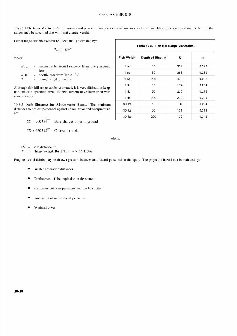
8132019 Articol despre explozii submarine
httpslidepdfcomreaderfullarticol-despre-explozii-submarine 1024
S0300-A8-HBK-010
10-35 Effects on Marine Life Environmental protection agencies may require salvors to estimate blast effects on local marine life Lethal
ranges may be specified that will limit charge weight
Lethal range seldom exceeds 650 feet and is estimated by
Table 10-3 Fish Kill Range Constants
Fish Weight Depth of Blast ft K
α
1 oz 10 328 0220
1 oz 50 385 0256
1 oz 200 475 0262
1 lb 10 174 0264
1 lb 50 235 0275
1 lb 200 272 0299
30 lbs 10 86 0284
30 lbs 50 131 0314
30 lbs 200 139 0342
H MAX = KW α
where
H MAX = maximum horizontal range of lethal overpressures
feet
K α = coefficients from Table 10-3
W = charge weight pounds
Although fish kill range can be estimated it is very difficult to keep
fish out of a specified area Bubble screens have been used with
some success
10-36 Safe Distances for Above-water Blasts The minimum
distances to protect personnel against shock wave and overpressure
are
SD = 300 W 13
Bare charges on or in ground
SD = 350 W 13
Charges in rock
where
SD = safe distance ft
W = charge weight lbs TNT = W times RE factor
Fragments and debris may be thrown greater distances and hazard personnel in the open The projectile hazard can be reduced by
bull Greater separation distances
bull Confinement of the explosion at the source
bull Barricades between personnel and the blast site
bull Evacuation of nonessential personnel
bull Overhead cover
10-1010-10
8132019 Articol despre explozii submarine
httpslidepdfcomreaderfullarticol-despre-explozii-submarine 1124
8132019 Articol despre explozii submarine
httpslidepdfcomreaderfullarticol-despre-explozii-submarine 1224
S0300-A8-HBK-010
10-41 Charge Weight Charge weight selection is based on two criteria
bull The charge must be large enough to perform the task
bull The charge must not be so large that it causes unacceptable damage to the casualty nearby structures or the environment
The minimum charge weight that will accomplish the task (in one shot) may be greater than the maximum charge weight what will not causedamage It is usually possible to perform the task in a series of steps each using charge weights smaller than the maximum acceptable weight
10-42 Underwater Blasting Water
Figure 10-11 Shared Charge Cutting Sequence
EXPLOSIVECHARGE
CONTAINER
LINER
CAVITY
SHAPEDCHARGE
(a)
S T A N D
- O F F
DETONA-TION WAVEAPPROACHESCAVITY LINER
(b)SHOCK WAVECOLLAPSESLINER INDUCINGJET FORMATION
(c)
CUTTING JETAPPROACHESTARGETSURFACE
(d) PLASTIC FLOW
IS INDUCED INTHE TARGETMATERIAL ANDTHE JET STARTSTO PENETRATE
(e)
JET PASSESTHROUGHTHE TARGET -CUT ISCOMPLETE
(f)
INITIATORpressure on the side of an object oppositethe explosive blast opposes the impact andexpansion of the explosive When the work involves moving large surface areasresistance to movement caused by waterpressure and hydrodynamic drag issignificant and explosive effectiveness isreduced For example it takes about onepound of explosive to break up and move acubic yard of rock in dry air Two to sixpounds of explosive per cubic yard arerequired to break and move the same rock underwater Explosive effectiveness is
further reduced as depth increases
Steel cutting by ribbon charges shapedcharges etc where little surface movementis required is not significantly affected byimmersion in water Shaped chargeeffectiveness is reduced if water cannot bedisplaced or evacuated from the cavity andstand-off (shaped charges are discussed inParagraph 10-421)
Most explosives detonate satisfactorilyunder water Some explosives containwater-soluble ingredients and aredesensitized with time when immersedunless sealed in waterproof containers
Certain explosives depend on dispersed microscopic air or gas bubbles for ease of initiation Immersion in deep water compresses the bubblesand renders them ineffective so they can be used only in shallow water or if specially formulated for deep water use Explosives dependingon dispersed bubbles for initiation include those based on or sensitized by nitroglycerine and nitroglycerol such as gelignites and blastinggelatins and those containing aqueous solutions of ammonium nitrate such as water gels and emulsions
Most military high explosives and commercial explosives based on PETN RDX and TNT can be used reliably in deep water because theyare not are not significantly water-soluble and do not depend on gas bubbles for initiation
Overlying water is an effective tamping agent but if the charge is not in intimate contact with the target the intervening water layer will largelynegate the tamping effect Even a thin water layer between the charge and target will dissipate some of the explosive energy before it reachesthe target The shock and compression waves pass through two media interfacesmdashexplosive to water and water to target energy is reflectedaway from the target at each interface If charges cannot be placed in intimate contact with the work additional tamping in the form of sandbags clay or soil should be used to overcome the dissipation of energy by the intervening water
Potential water tamping lends a slight theoretical advantage to blasting from the wet side of a hull but offsetting advantages accrue whenexplosives are placed in the dry
bull Explosives fuses and initiators are not subject to the desensitizing effects of water immersion or to disturbing forces of currentand surge
bull Charges can be placed more effectivelymdashit is easier to secure charges and intimate contact with the target surface can be attained
bull Charges and firing circuits can be inspected immediately before firing
bull There is greater control over the personnel placing explosives and their work can be monitored and inspected with less effort
Immersion time prior to firing should be minimized to reduce the desensitization of the explosives and the possibility that current or surge willdislodge charges or initiating circuits
10-1210-12
8132019 Articol despre explozii submarine
httpslidepdfcomreaderfullarticol-despre-explozii-submarine 1324
S0300-A8-HBK-010
10-43 Cutting and Fracturing Charges A principal use of explosives in salvage is cutting hull plating and structure in ships High-velocitybrisant explosives such as TNT and plastic explosives are best for cutting steel or aluminum Structural members are cut by a variety ocharges
bull Shaped charges ndash A lined or unlined cavity in the explosive produces a high-energy cutting jet
bull Fracturing charges ndash Specialized charge geometry causes convergence of strain waves in the target
bull Simple contact charges ndash Breakage is accomplished by the combined but uncoordinated effects of shock waves strain pulses angas expansion
Shaped and fracturing charges are far more efficient than contact charges and should be used when available and when suited to working conditions Because of their relatively small charge weights shaped and fracturing charges must be placed precisely and must be held in positioagainst current or surge to be effective If charges cannot be placed precisely better results may be obtained with less efficient contact charge
10-431 Shaped Charges A hollowed-
Figure 10-12 Typical Shaped Charges for Salvage Work
FLEXIBLE LINEARSHAPED CHARGE
BOX TYPELINEAR CHARGE
EXPLOSIVE
TARGET
CASE
METALLINER
ENCLOSED
STAND-OFFSPACE
CYLINDRICALCHARGE
EXPLOSIVECORE
DENSEFLEXIBLE
SHEATH
WOODENSPOOL
out or shaped charge detonated against ahard surface produces a crater that isapproximately a mirror image of the chargecavity The shaped charge is initiated at apoint behind the cavity the detonation waveexpands omnidirectionally from theinitiation point or axis Reaching the cavitythe detonation wave converges on a plane
(for linear charges) or axis (in cylindricalcharges) perpendicular to the target surfaceThe convergence of the shock waveconcentrates the explosive energy in a smallarea The resultant cratering is called the
Munro Effect If the charge is lined withmetal or other dense material the explosioncollapses the liner and carries it in the shock wave to the target surface as a slug (orblade) of metal and hot gas that acts as acutting jet The jet heats and erodes thetarget surface Shock-wave pressure and jeteffects combine to induce plastic flow in thetarget and cut through the material Figure10-11 illustrates the cutting sequence for alined shaped charge
For optimum effect shaped charges arepositioned at a stand-off distance from thetarget surface to allow the penetration jet toform completely before it reaches the targetsurface Optimum stand-off varies with thecavity angle and charge size stand-off isd et er m in ed f r om t ec hn ic al o rmanufacturerrsquos data for the charge used
Various-sized cylindrical shaped chargesare made for hole cutting Linear chargesare used for long cuts Linear charges areusually made in the form of a box with thecavity liner set across the inside of the boxas shown in Figure 10-12 Flexible linearshaped charges can conform to irregular
surfaces and cut lines Well-designedlinear cutting charges obtain good resultswith relatively small charge weightsIndividual charge weight and explosiversquosconsumption are based on data publishedfor the particular explosives used Data formilitary shaped charges is given in the Technical Manual for the Use of Explosives in Underwater Salvage (NAVSEA SW061-AA-MMA-010Typical manufacturerrsquos data for linear shaped charges are shown in Figure 10-13 (Page 10-14)
10-110-1
8132019 Articol despre explozii submarine
httpslidepdfcomreaderfullarticol-despre-explozii-submarine 1424
S0300-A8-HBK-010
Shaped charges can be improvised as
Figure 10-13 Typical Manufacturerrsquos Data for Linear Shaped Charges
STAND-OFF FOR OPTIMUM PERFORMANCE(RDX OR PETN EXPLOSIVE)
MINIMUM CUTTING PERFORMANCEAT OPTIMUM STAND-OFF
MINIMUM CUTTING PERFORMANCEAT OPTIMUM STAND-OFF
MINIMUM CUTTING PERFORMANCEAT OPTIMUM STAND-OFF
MINIMUM CUTTING PERFORMANCEAT OPTIMUM STAND-OFF
5
30 15
10
05
02
01
2010
JETCORDSTAND-OFFTARGET
05
02
01
05
0201
01
02
05
01
02
01
02
05
10
20
02
05
01
02
05
10
1 0
2 0
3 0
4 0
5 0
1 0 0
2 0 0
EXPLOSIVE CORELOAD GRAINSFOOT
EXPLOSIVE CORELOAD GRAINSFOOT
EXPLOSIVE CORELOAD GRAINSFOOT
EXPLOSIVE CORELOAD GRAINSFOOT
NOTE CUTS AT 7 AND 10 GRFTMADE AT ZERO STAND-OFF
EXPLOSIVE CORELOAD GRAINSFOOT
100
5
5
10
10
50 100 200 500 1000
20
20
50
50
100
100
200 500
200 500 1000 2000 5 0 0
S T A N D
- O F F I N C H E S
T H I C K
N E S S
C U T
I N
C H E S
T H I C K N E S S
C U T
I N
C H E S
T H I C K N E S S
C U T
I N
C H E S
T H I C K N E S S
C U T
I N
C H E S
1 0 0 0
2 0 0 0
A L U M
I N U M
S H E A
T H
C O P P
E R S H E A
T H
L E A D
S H E A
T H
C 1 0 1 8 S T E E
L T A R G
E T
COPPER-SHEATHEDJETCORD (RDX ORPETN EXPLOSIVE)
LEAD-SHEATHEDJETCORD (RDX ORPETN EXPLOSIVE)
2024-T351ALUMINUM
TARGET
C10118STEELTARGET
2024-T351ALUMINUM
TARGET
C10118STEELTARGET
ALUMINUM-SHEATHEDJETCORD (RDX
OR PETN EXPLOSIVE)
SILVER-SHEATHEDJETCORD
(DIPAMEXPLOSIVE)
CUT7075-T6
ALUMINUMTARGET
OPTIMUMSTAND-OFF
shown in Figure 10-14 When performance
data for a particular material is not
available cutting ability can be estimated
from the following
where
t = t o
ρρ
o
t = unknown cutting capacity
(thickness) in material of
density ρt o = known cutting capacity in
material of density ρo from
manufacturerrsquos data
Water in the stand-off and cavity prevents
the formation of the cutting jet Theenclosed stand-off of box-type shaped
charges excludes water but boxes can
withstand hydrostatic pressures only to
shallow depths that vary with the particular
unit For depths of 30 to 60 feet the stand-
off can be filled with closed-cell plastic
foam The foam inhibits jet formation
slightly so that performance is decreased
For deeper immersion the stand-off and
cavity must be constructed to withstand
hydrostatic pressure or made free flooding
and then evacuated with compressed air or
gas at depth For underwater use flexible
linear charges can be enclosed in flexibletubes filled with foam or evacuated by
compressed gas One manufacturer markets
a line of circular cutters prefabricated with
compressed gas fittings
10-432 Fracturing Charges A diamond-shaped sheet of plastic explosive laid on a steel plate and detonated simultaneously from two
opposite corners will fracture the metal along a line between the two uninitiated corners This effect is shown in Figure 10-15(a) The fracture
mechanism depends on the pressure rise as the shock waves from the two detonating points collide followed by the relaxation as the waves
pass through one another and the combined effect of two tension waves rebounding from the far side of the target This arrangement is a
diamond charge and is suitable for cutting bars and pipes but has limited application for plate cutting because the fracture extends only slightly
beyond the charge
The diamond charge principle was first applied to extended plate cutting in fracture tape Fracture tape shown in Figure 10-15(b) consists of
a series of diamond charges connected by continuous strips of explosive along the edges of the charges Fracture tape has seen only limiteduse because it was not manufactured in a flexible form The charge may fail to cut if bilateral asymmetry develops between the two initiation
trains Fracture tape can be improvised by cutting explosive sheet to the appropriate shape
Shock-wave refraction tape (SRT) is a recently developed explosive charge that works on the principle of shock-wave collision within metal
targets In this charge a continuous strip of explosive is molded to the back of an inert wave-shaping element as shown in Figure 10-15(c)
One manufacturer uses magnetic rubber as the wave-shaping element providing both flexibility as well as an attachment method (provided the
surfaces are clean and smooth) The performance of shock-wave refraction tape is comparable to that of shaped charges when cutting ordinary
steels very high strength fracture-resistant steels may not be cut as easily There is no cavity or stand-off to flood so SRT is more adaptable
to underwater use than linear shaped charges
10-1410-14
8132019 Articol despre explozii submarine
httpslidepdfcomreaderfullarticol-despre-explozii-submarine 1524
S0300-A8-HBK-010
Figure 10-14 Improvised Shaped Charges
SHEETEXPLOSIVE
STEEL ORALUMINUM
ANGLE
PLASTICEXPLOSIVE
PLASTICEXPLOSIVE
CONE
WINEBOTTLE
STICKS TAPEDTO SIDE ASSTAND-OFF
FUSE
CAP
S T A N D - O
F F
D I S T A N C E
FOOD CANWITH BOTHENDS CUT
OUTPLASTICEXPLOSIVE
SHEETMETALOR LEADSHEETCONE
RIVET
SIDES OFCAN FORMSTAND-OFF
CAP
80˚ - 90˚
Figure 10-15 Fracturing Charges
A
Arsquo
A ArsquoEXPLOSIVE
FRACTURE
EXPLOSIVESHOCK-WAVEFRONTS
REFLECTEDTENSION WAVE
(a) DIAMOND CHARGE (INITIATED AT POINTS A AND Arsquo)
(c) SHOCK-WAVE REFRACTION TAPE (SRT)(b) FRACTURE TAPE
EXPLOSIVE
INERT BARRIERSINITIATION POINT
EXPLOSIVE
WAVE-SHAPINGELEMENT
FRACTURES TENSIONWAVE
SHOCK WAVE
10-110-1
8132019 Articol despre explozii submarine
httpslidepdfcomreaderfullarticol-despre-explozii-submarine 1624
S0300-A8-HBK-010
10-433 Contact Charges Simple
Figure 10-16 Steel Cutting Contact Charges
DETONATINGCORD
EXPLOSIVE
STEEL PLATE
WELDS
STEELCHANNEL
STUD
PLATE
SECURINGSTRAP
EXPLOSIVESHEET OR
PLASTICEXPLOSIVE
contact charges require much heaviercharges than shaped or fracturing chargesExplosive performance can be increasedand charge weight reduced by carefulcharge placement confinement tampingand by scoring cut lines with cuttingtorches or mechanical cutters Some
effective charge placements and geometryare shown in Figure 10-16
Charge weights can be estimated from thefollowing relationships
where
W = 3
8 A Structural steel
W = D 2 High carbon or alloy steel
W = charge weight lbs TNT
A = cross-sectional area of sectionto be cut in2
D = diameter or thickness of section to be cut in
To determine charge weights for explosivesother than TNT the TNT charge weight isdivided by the relative effectiveness (RE)factor
10-434 Charge Placement Cutting charges are most effective when the cut line is adjacent to but not on a rigid portion of the target surfaceThe target must be restrained from moving away from shaped and fracturing charges so the explosive energy is expended in cutting or fracturingthe target rather than pushing it away Contact charges create a strong shearing action along the line between the movable and rigid surfaceHull cutting charges are most effective when slightly offset from frames
bull If placed in the middle of the span a large portion of the explosive energy is expended in deflecting the plate
bull If placed directly over a stiffener both the stiffener and the plate must be cut
For efficient cutting charges must be placed in intimate contact with the target surface Charges must be secured to all vertical steeply angledand overhead surfaces and to horizontal surfaces where current wind vibration or target movement may dislodge them Where no tie-downpoints exist the following securing methods can be used
bull Light metal straps bolted to studs explosively set or friction welded along each side of the cut line
bull Tie-down wires lines or bongee cords inserted through holes cut drilled or burned through the plating (tie-downs can also beled to studs or magnetic clamps)
bull Sandbags or similar weights placed on charges on horizontal surfaces
bull Backing charges with magnetic strips adhesive strips or small suction pads (these methods have had limited success)
bull Hose charges can be stretched between tie-down points over flat or smoothly convex surfaces
10-435 Ship Sectioning Explosives are commonly used to section wrecks for piecemeal removal or to separate a casualty into two piecesso that one part can be salvaged Ship sectioning including explosive methods is discussed in the US Navy Ship Salvage Manual Volume 2(S0300-A6-MAN-020) The following notes supplement that discussion
10-1610-16
8132019 Articol despre explozii submarine
httpslidepdfcomreaderfullarticol-despre-explozii-submarine 1724
S0300-A8-HBK-010
When cutting a ship transversely the internal structure must be cut as well as the more accessible hull plate and stiffeners It is very difficu
to obtain complete separation in a single shot Salvors should plan to make cuts in several shots or have thermal or mechanical cutting gea
available to sever stubborn structure
In a landmark operation in 1973 the salvageable aft section of a 960-foot laden ore carrier was explosively separated from the forward part o
the ship which was abandoned The ship had sunk by the bow in 130 feet of water With holds 7 8 9 and 10 their associated wing and
double-bottom tanks and the machinery spaces dry the after section was buoyant and afloat The hull was cut in way of number 7 hold b
more than 1800 feet of custom engineered and fabricated high speed explosive cutters All cutters were placed in the dry number 7 wing anbottom tanks Instantaneous separation (necessary to prevent capsize of or damage to the aft section) was attained by
bull Placing cutters against all bulkheads shell plating stringers void tank sections and pipes extending through the transvers
bulkhead separating holds 7 and 8
bull Taking advantage of the vertical shear on the hull resulting from the weight of the forward section laden with 90000 tons of ore
and the buoyancy of the after section and
bull Maintaining a 300-ton horizontal astern pull on the after section as the cutters were detonated
Blast curtains were rigged in the number 7 tanks and hold and the number 8 wing and bottom tanks were pressurized with compressed air to
protect the separating bulkhead A diverrsquos survey after the successful separation revealed no damage to the bulkhead The operation was mad
possible by the salvorsrsquo employment of specialist explosives engineers who custom designed the explosive cutters taking into account permissiblblast effects on the aft number 7 bulkhead gas generation and dispersion requirements mutual interference between charges and the strength
of hull structural members See The Cutting of the Igara in Reedrsquos Commercial Salvage Practice for a more detailed discussion of th
operation
The order in which the different members are to be cutmdashas well as the methods to be usedmdashmust be considered carefully Preliminary cut
should not weaken the structure to the point that it is in danger of collapsing and injuring personnel placing charges for subsequent cuts
Cutting methods are frequently combined A hull can be opened up with explosives to permit access to internal structure to be cut by mechanica
or thermal methods In some cases preparatory weakening cuts are made by divers with oxy-arc or exothermic torches with the final cuts mad
explosively
Simple types of ships are better candidates for explosive sectioning than more complex types The following ship types lend themselves t
explosive sectioning
bull Transversely framed ships because there are fewer longitudinal stiffeners to cut
bull Freighters and bulk carriers because most do not have centerline longitudinal bulkheads (some bulk carriers have wing tanks whos
inner bulkheads must be cut) Small ships often do not have double bottoms
bull Small single-product tankers because they do not have wing tanks or double bottoms
The following ship types are not good candidates for explosive sectioning
bull Longitudinally framed ships because of the large number of longitudinal stiffeners
bull Passenger ships and warships because of their extensive joiner work internal subdivision wireways piping and ventilatio
systems
bull Large tankers and product carriers because they are constructed with two or more longitudinal bulkheads
bull Freighters with insulated holds
10-110-1
8132019 Articol despre explozii submarine
httpslidepdfcomreaderfullarticol-despre-explozii-submarine 1824
S0300-A8-HBK-010
10-44 Seafloor Blasting Seafloor
Figure 10-17 Obstruction Blasting
CONTACT BLASTING MUDCAPPING
SNAKEHOLING
STEMMINGSTEMMING
CHARGE
CHARGE
BLOCKHOLING
blasting moves large amounts of seafloor
material by channeling trenching etc or
removes isolated obstructions such as
pinnacles coral heads and boulders The
basic techniques are
bull Contact Blasting ndash Chargesare placed on the formation
to be blasted either indi-
vidually or in line or
checkerboard patterns The
detonating explosive imparts
a violent blow to the seafloor
material The efficiency of
contact blasting depends on
maintaining intimate contact
with the material to be
blasted Contact blasting is
the least efficient blasting
method in terms of explosive
consumption but requires the
least time and effort to
prepare and set charges
bull Boreholes ndash Internal charges
are placed in boreholes
drilled or augured into the
object or strata to be blasted
10-441 Rock Blasting The choice of explosive for a particular rock-blasting job depends on the hardness and density of the rock and the
type of breakage desired Fast brisant explosives such as TNT or composition C-4 are required to break most kinds of rock although slower
explosives are effective on soft rock such as limestone
Rock is weakest in tension so internal charges are most effective Contact blasting depends on the tamping effect of overlying water to confine
the explosion momentarily and is effective only on soft rock and coral where the material is broken by crushing rather than shattering The
rock fragments are moved by the expanding gases so high gas production is required to move dense rock If the object is to break up rock for
removal by nonexplosive means gas production of the explosive is less important Individual boulders are broken by one of the methods
discussed below The methods are illustrated in Figure 10-17
bull Mudcapping ndash A contact charge is covered with 10 to 12 inches of mud clay or moist soil tamping Plastic clay is the most
effective tamping Loose sand should not be used but sandbags are effective
bull Snakeholing ndash The charge is placed in a hole jetted bored or otherwise excavated under an object lying on or partially buried
in a soft seafloor Snakeholing is more effective than mudcapping under all conditions and requires about one-half as much
explosive as contact blasting
bull Blockholing ndash The charge or charges are placed in one or more boreholes Explosive effect can be altered by changing charge
weights and placement rock formations boulders concrete structures etc can be completely demolished be broken into
fragments of varying size or have portions broken off Blockholing requires about one-third as much explosive as contact blasting
Table 10-4 gives approximate explosive requirements in pounds per
Table 10-4 Powder Factors (lbyd3) for Rock Blasting
Blas ting Metho d A ir B la sting Und erwater Blas ting
Contact Blasting Not effective 6 - 20
Mudcapping 1 - 2 4 - 15
Snakeholing 1 - 11 frasl 2 3 - 10
cubic yard or powder factor for different rock-blasting methods A
range of powder factors for each method is given The actual powder
factor for any project will depend on
bull The relative density and toughness of the rock
bull Whether individual boulders or massive rock formations
are being blasted
bull Water depth
10-1810-18
8132019 Articol despre explozii submarine
httpslidepdfcomreaderfullarticol-despre-explozii-submarine 1924
S0300-A8-HBK-010
The lower values in Table 10-4 are based
Table 10-5 Rock Density and Toughness
Type of Rock Density lbft3 Relative Toughness (Limestone = 1)
Andesite 150 - 175 11
Basalt 150 - 200 17 - 23
Conglomerate 125 - 162 NA
Dioritic 156 - 200 19 - 21
Felsite 150 - 200 NA
Gabbro 169 - 200 NA
Granite 156 - 194 15 - 21
Gneiss 150 - 181 10 - 19
Limestone 160 - 187 10
Marble 131 - 181 NA
Quartzite 125 - 200 19 - 27
Sandstone 124 - 194 15 - 26
Schist 150 - 175 10 - 21
Shale 112 - 194 NA
Slate 156 - 194 12
on blasting massive limestone at depths of 30 to 60 feet Values high in the range areused with tougher or denser rocks andgreater depth Lower values are used whenblasting individual boulders or outcrop-pings Table 10-5 compares densities andtoughness of common rocks
Rock blasting by internal charges is mosteffective when there is a free face approxi-mately parallel to the borehole Thedetonation of the explosive creates a highgas pressure in the charge hole generating acompressive strain pulse in the surroundingrock The compressive pulse travels outwardin all directions Near the hole theamplitude of the strain pulse is sufficient tocrush the rock Amplitude decays rapidly asthe pulse travels outward until it can nolonger crush the rock The pulse travels out-ward until it is reflected from a free surfaceas a tensile strain pulse As rock is much
Figure 10-18 Excavation Rock Blasting
DRILLING FACE
WORKING OR FREE FACE
BOREHOLE
BENCH
EXCAVATION FLOOR(PROJECT DEPTH)
L
B
BltL
INSUFFICIENT EXPLOSIVEENERGY RELEASE AT
BOTTOM OF HOLE
B
MAINFRACTURELINES
COLUMN LOADEDHOLE
45˚
STRESS PATTERN FOR ACONCENTRATED CHARGE
IN BOTTOM OF HOLE
REFLECTEDTENSION WAVE
UNREFLECTEDCOMPRESSIONWAVE
TOE
weaker in tension than compression the
tensile pulse is able to break the rock pro-gressing from the free face back towards thecharge hole The expanding gases in thecharge hole are not directly responsible formuch of the rock breakage to some extentthe rock is pulled apart rather than pushedapart
Blasting massive seafloor rock formations issubject to constraints similar to those en-countered in quarry blasting and similarmethods are employed Detailed informationon rock blasting is found in publications onmining and quarrying For effective blastingit is necessary to establish a breaking orworking face at an angle to the drilling faceThe drilling face is most often the horizontalseafloor the working face is vertical orinclined from the vertical by an angle of 45degrees or less The working face is brokenback in steps by detonating charges in rowsof holes behind the face For cuts deeperthan the maximum practical drilling depththe working face is broken back in stages byestablishing intermediate floor levels orbenches as shown in Figure 10-18
A working face can be established in aflush surface by blasting out a crater with asingle charged hole cluster of holes or lineof holes Empty relief holes between andaround charged holes provide free faces toreflect strain pulses and space for displaced
rock to move into The excavation floorand work face can be squared up bysubsequent blasting
Boreholes can be drilled by diver-operated jackhammers or rock drills for smalloperations For extensive drillingoperations a spud-moored drill barge or asubmersible crawler-mounted rock drillshould be used
10-110-1
8132019 Articol despre explozii submarine
httpslidepdfcomreaderfullarticol-despre-explozii-submarine 2024
S0300-A8-HBK-010
10-442 Coral Blasting Coral is difficult
Figure 10-19 Coral Blasting
13
13
12
12
11
11
10
10
9
9
8
8
7
7
6
6
5
5
4
4
3
3
2
2
1
1
0
0
DEPTH AND WIDTH OF CUTS MADE IN CORAL WHEN BLASTING WITH CAVITY CHARGES
DEPTH AND WIDTH OF CUTS MADE IN CORAL BY STANDARDUS MARK 8 DEMOLITION CHARGES
VOLUME OF CORAL REMOVED USING9-KG (20 POUND) CHARGES
CRATER WIDTH IN FEET
CRATER WIDTH IN FEET
NUMBER OF PACKS
V O L U M E
I N
C U B I C
F E E T
1 2 3 4 5
1
1
2
2
3
3
4
4
5
5
6
6
7
7
8
8
9
9
10
10
11
11
12
12
13
13
1
1
2
2
3
3
4
4
5
5
100
20
30
40
50
60
70
80
90
100110
D E P T H
I N
F E E T
D E P T H
I N
F E E T
to blast because of its porosity High-velocity explosives have been successfulbut slow-detonating explosives are moreeffective Coral will clog rock drills sointernal charges are set in powder points(pipes driven into the formation) Powderfactors for coral are about five pounds per
cubic foot for mushroom-shaped coralheads and higher for solid headsDemolition of an above-water coralformation requires about three times asmuch explosive as an equivalent underwaterformation unless a well-placed thoroughlytamped internal charge is used Linecharges can be used to cut trenches orchannels in coral Figure 10-19 showstypical results of coral blasting
10-443 Blasting ImpalementsRemoving an impaling rock or coral head isa slow and tedious process The chargesmust be large enough to break the rock orcoral but light enough that they do not
damage the ship or drive the impalementfurther into the ship The only feasibleprocedure is to begin with very smallcharges and check the results after eachshot Charge size can be increasedincrementally if there is no hull damage orthe same charge can be repeated until theimpalement is gradually severed or brokenaway A large internal concrete patch overthe impalement and surrounding platingstrengthens the hull against shock loadingso that larger charges can be used Theimpalement should be cut off about twofeet below the hull
When external access to the impalement isdangerous or impossible the impalement isattacked from the inside The bestprocedure is to use small charges inshallow boreholes with interspersed relief holes to progressively shatter theimpalement and lower it sufficiently toclear the hull Doors and hatches should beopen during blasting to prevent the hull from being pressurized internally by the explosive gases It may be necessary to build a trunk aroundthe impalement to provide a watertight enclosure and to vent explosive gases to the atmosphere
10-444 Setting Anchors Anchors can be set in hard pan coral clay or mud bottoms with explosives Small charges are set near the anchoras shown in Figure 10-20 and detonated The anchor is lifted and dropped into the blast crater At the same time a quantity of loose or brokenseafloor is lifted out of the crater and some of this material will settle on the anchor Anchors can be explosively settled into seafloors subjectto liquefication under high-frequency cyclic loading such as clean medium- or low-density cohesionless soils A number of small chargesdetonated sequentially on short delay in the vicinity of the anchor can liquefy the soil allowing the anchor to settle into the seafloor underits own weight
10-445 Channeling in Soft Bottoms Military dynamite or other low-velocity low-brisance explosives are best for moving soft plasticmaterial Powder points contact charges charges in augured or excavated holes or hose charges in checkerboard or linear patterns are usedContact blasting will normally dig a channel or crater four to five feet deep Deeper cuts can be attained by driving powder points to the desiredchannel depth plus the distance between points Powder factors are three to five pounds of explosive per cubic yard of soil Alternate pointsshould contain charges of different weights so that the detonation waves do not cancel one another Soft seafloors are almost always excavatedmore effectively by nonexplosive means such as dredging or scouring
10-2010-20
8132019 Articol despre explozii submarine
httpslidepdfcomreaderfullarticol-despre-explozii-submarine 2124
S0300-A8-HBK-010
10-45 Concrete and Masonry Blasting
Figure 10-20 Setting Anchors with Explosive Charges
CHARGESANCHOR
FIRING SYSTEM BLASTING CAP
BUOY
DETONATING CORD MADEUP TO WORKING LINE
LIGHT LINE TO KEEP STRAINOFF DETONATING CORD
Concrete and masonry are blasted by thesame methods as rock Simple concretedispersal requires about one pound of explosive per cubic foot Breachingcharges for concrete and masonry structuresare estimated by
W = R
3
KC where
W = charge weight lbs TNT R = breaking radius ft
= thickness for externalcharges
= distance to outside surfacefor internal charges
K = material factor from Table10-6
C = tamping factor from Figure10-21 (Page 10-22)
10-46 Timber and Pile Cutting Forcutting timber high-velocity brisant
explosives work best but low-velocityexplosives are effective when appliedproperly Charge weights vary as thesquare of the diameter of the timberEmpirical relationships for determiningcharge weights are given below
where
W = D 2
4Untamped external charges
W = D 2
250Tamped internal charges
Table 10-6 Material Factor K for Concrete Breaching Charges
Material R K
Poor masonry shale and hardpan All values 0225
Good masonry ordinary concrete rock
Less than 3 ft
3 to 5 ft
5 to 7 ft
More than 7 ft
035
0275
025
0225
Dense concrete first-class masonry
Less than 3 ft
3 to 5 ft
5 to 7 ft
More than 7 ft
045
0375
0325
0275
Reinforced concrete (concrete only will
not cut reinforcing steel)
Less than 3 ft
3 to 5 ft
5 to 7 ft
More than 7 ft
070
055
050
0425
W = charge weight lbs TNT D = diameter of round or leastdimension of dressedtimber in
For explosives other than TNT chargeweight is determined by dividing the TNTcharge weight by the relative effectiveness(RE) factor
10-47 Reducing Underwater ShockWave Pressure and Impulse Shock waves damage structures by two differentmechanisms
bull The peak shock wave pressureexceeds the compressive strengthof the material
bull The impulse causes structural elements to vibrate with their natural frequency The deflection may be great enough to cause damageImpulse caused vibrations can cause damage even when the peak pressure does not exceed the compressive strength of the material
Shock wave pressure or impulse at a structure can be reduced by charge placement bubble screens and in the case of multiple charges firingsequence
10-210-2
8132019 Articol despre explozii submarine
httpslidepdfcomreaderfullarticol-despre-explozii-submarine 2224
S0300-A8-HBK-010
10-471 Charge Placement Observations
Figure 10-21 Tamping Factor C for Concrete Breaching Charges
C = 45
C = 25 C = 20 - 25
C = 23C = 35
C = 20 C = 15
C = 25
UNTAMPED CHARGES
TAMPED CHARGES
R
R R
R
R
R R
R
t 03tltdltt
D
C = 125C = 125
STEMMED PLACED IN
CENTER OFMASS
C = 125 - 10
R
t dgtt
DR
R
FILL
Figure 10-22 Shock Wave Effects for Various Blasting Conditions
NOTE
620PSI
50PSI
29PSI
14 MS
13 MS
2 MS
(a) 33 FT FROM 1LB CHARGEIN FREE WATER
EXTRAPOLATED FROM DATAFOR POINT 47 FT FROM 3LBCHARGE IN FREE WATER
NOTEEXTRAPOLATED FROM DATAFOR POINT 47 FT FROM 2LBCHARGE IN 29 FT3 OF ROCK
(b) 33 FT FROM 1LBCHARGE IN ROCK
(c) 33 FT FROM 1LB CHARGEIN FREE WATER THROUGHBUBBLE SCREEN(0043 FT3SEC PER FT)
of underwater rock blasting operations haveshown that peak pressures for explosiveswell packed in bore holes is much less thanthat of charges in the water Figure 10-22compares time pressure curves 33 feet froma one pound charge in free water and thesame sized charge in submerged rock Thegreat difference in peak pressures and totalimpulse indicates that a principal means of reducing underwater shock wave effects isto ensure that charges are not detonated whileexposed to free water In seafloor orobstruction blasting internal charges shouldbe used The top portions of boreholes fora distance of 15 times the borehole diametershould be left uncharged Blasting patternsshould be arranged to avoid sympatheticdetonation and ensure that charges to bedetonated later in a firing sequence are notexposed by rock breakage from earlierdetonations Heavy sandbag or clay tampingover cutting charges can significantly reduceshock effects in the surrounding area
10-472 Bubble Screens An impingingshock wave compresses the bubbles of abubble screen over a period of somemilliseconds On their subsequent re-expansion over a period of milliseconds thebubbles emit new compression waves withlower peak values The part of the shock wave that passes between the bubbles isalso attenuated Increasing the number of air bubbles increases the reduction in peak pressure but also increases the duration of the pressure on the side of the bubblescreen away from the blast Investigationsby AT Edwards at the Hydro-electricPower Commission of Ontario showed thatthe peak pressure 33 feet from a one poundcharge was reduced by a factor of 10 by anintervening bubble screen produced by anair flow of 0043 cubic feet per second perfoot of pipe Doubling the air flow reducedpeak pressure by a factor of 70 at the samedistance with the same charge weight At164 feet the corresponding reductionfactors were 8 and 40 Three inchdiameter pipe was used in the experimentswith groups of two diametrically opposite1 frasl 16-inch holes spaced 3 frasl 4-inch or 11 frasl 2 inchesapart Figure 10-22 shows the pressure-time history 33 feet from a one poundcharge with an intervening water curtain
In reducing peak pressure while simultan-eously extending the decay time the bubble
screen redistributes but does not decrease to-tal impulse Bubbles screens are ineffectivein preventing damage in most cases wherethe damage mechanism is primarily impulse
10-473 Firing Sequence In multiple-charge shot-delay shots firing the chargesclosest to the structure to be shielded firstwill reduce the impulse transmitted to thestructure by the delayed charges Theimpulse from the delayed charges is partlyscreened off by explosion gases (and brokenrock when seafloor blasting) from earliercharges
10-2210-22
8132019 Articol despre explozii submarine
httpslidepdfcomreaderfullarticol-despre-explozii-submarine 2324
S0300-A8-HBK-010
10-5 PERMITS
Authorization from the appropriate fleet commander is required for all underwater explosives detonations OPNAVINST 85302 lists the basi
requirements to be met before using demolitions Amplifying instructions in the 8530 series have been issued by fleet commanders
Some of the additional permits required from various Federal and local agencies are described in the following paragraphs It may take man
months to obtain all the required permits Planning for explosives operations should start well in advance and be coordinated carefully so thaall permits are valid over the desired time frame and that other salvage tasks that proceed sequentially or concurrently with the explosive
operations are ready on schedule
10-51 Corps of Engineers Section 10 of the River and Harbor Act of March 3 1899 (30 Stat 1151 33 USC 403) prohibits the obstructio
or alteration of any navigable water of the United States without authorization from the Secretary of the Army Requirements for and limitation
of permits are described in Title 33 of the US Code of Federal Regulations (33 CFR) Article 209120 Detailed information concerning th
permits required for a specific project can be obtained from the local Corps of Engineers Office or from the Department of the Army Offic
of the Chief of Engineers Washington DC 20314
10-52 Environmental Impact Statement Explosives projects that may have an adverse effect on the environment may require the filing o
an Environmental Impact Statement Information on the filing of the statement is found in OPNAVINST 50901 (series)
10-53 State and Local Agencies The number and kind of permits required for explosives operations varies widely from location to location
A partial listing of agencies that may require permits includes
bull State Fish and Game Commission
bull State Lands Commission
bull State Oil and Gas Commission
bull StateEnvironmental Commission Department of Environmental ManagementEnvironmental Protection Agency or similar agency
bull County Board of Supervisors
bull Local police or sheriff
bull Fire Marshal
bull City Engineer
10-6 OPERATIONAL NOTES
10-61 Test Shots Because of the imprecise nature of charge weight and blast effect calculations test shots should always be made before
or at the beginning of an explosives job Test shots are made to determine two quantities
bull The minimum charge weight required to perform the task
bull The maximum charge weight that will not cause unacceptable damage to the casualty nearby structures or the environment
Tests to determine minimum charge weight should be conducted well before the operation at an explosives range or remote site
The maximum acceptable charge weight is estimated by calculation and verified by on-site test shots Test shots are usually conducted as th
first working shots Test shots start with charges lighter than those calculated for the job gradually increasing the charge weights until th
minimum charge weight to perform the task is reached or blast effects become unacceptable
10-210-2
8132019 Articol despre explozii submarine
httpslidepdfcomreaderfullarticol-despre-explozii-submarine 2424
S0300-A8-HBK-010
10-62 Explosives Expertise The importance of seeking the advice of experienced hands for explosives projects cannot be overemphasized
There is no program in the US Navy to train or certify salvage demolitions specialists Navy first class divers and diving officers receive
limited explosives demolitions training Explosive ordnance disposal (EOD) divers and special warfare swimmers (SEAL) receive additional
training in specialized procedures that are not always applicable to salvage The particular demolitions expertise of a Navy diver is a function
of on-the-job experience that may vary from extensive to none In the absence of personnel experienced in salvage demolitions advice may
be sought from Navy Mobile Construction Battalions or the Army Corps of Engineers Commercial explosives consultants may be retained
through the Supervisor of Salvage
10-63 US Military Explosives A wide variety of explosives in various types of demolition charges are maintained in the system for use
by military forces These explosives and charges are described in the Navy technical manuals Use of Explosives in Underwater Salvage
(NAVSEA-SW061-AA-MMA-010) and Demolition Materials (NAVSEA OP 2212) and the Army field manual Explosives and Demolitions (FM
5-25) A summary of the characteristics of US Military explosives is given in Table 10-7
Table 10-7 Characteristics of Military Explosives
Explosive Typical Uses
Rate of Detonation
(Feet per Second)
Relative Effectiveness as
an External Charge
(TNT = 100)
Intensity of
Toxic Fumes
Water
Resistance
Amatol Bursting Charge 16000 fps 117 Dangerous Poor
Ammonium Nitrate Cratering Charge and
Composition Explosives 8900 fps 042 Dangerous None
Black Powder Time Blasting Fuse 1300 fps 055 Dangerous None
Composition A-3 Booster Charge and Bursting
Charge 26500 fps 126 Dangerous Good
Composition B Bursting Charge 25600 fps 135 Dangerous Excellent
Composition C-3 Demolition Charge 25000 fps 126 Dangerous Good
Composition C-4 Demolition Charge 26500 fps 126 Dangerous Excellent
HBX-1 and HBX-3 Demolition Charge 24300 fps Air 148
Underwater 168 Dangerous Excellent
H-6 Demolition Charge 24300 fps Air 148
Underwater 168 Dangerous Excellent
Pentolite 5050
Booster Charge and Bursting
Charge 24600 fps 126 Dangerous Excellent
PETN Detonating Cord Blasting Cap
and Demolition Charge 26000 fps 166 Dangerous Excellent
RDX Blasting Caps Composition
Explosives 27400 fps 160 Dangerous Excellent
Tetryl Booster Charge and
Composition Explosives 23300 fps 125 Dangerous Excellent
Tetrytol 7525 Demolition Charge 23000 fps 120 Dangerous Excellent
TNT Demolition Charge and
Composition Explosives 22500 fps 100 Dangerous Excellent
TNT is used as the standard (TNT = 100) for comparison of the effectiveness of other explosives
10-64 Commercial Explosives A variety of commercial explosives and explosive devices are available including highly effective custom-
made steel cutting charges liquid explosives gelatins etc The Supervisor of Salvage should be contacted if the use of commercial explosives
is indicated
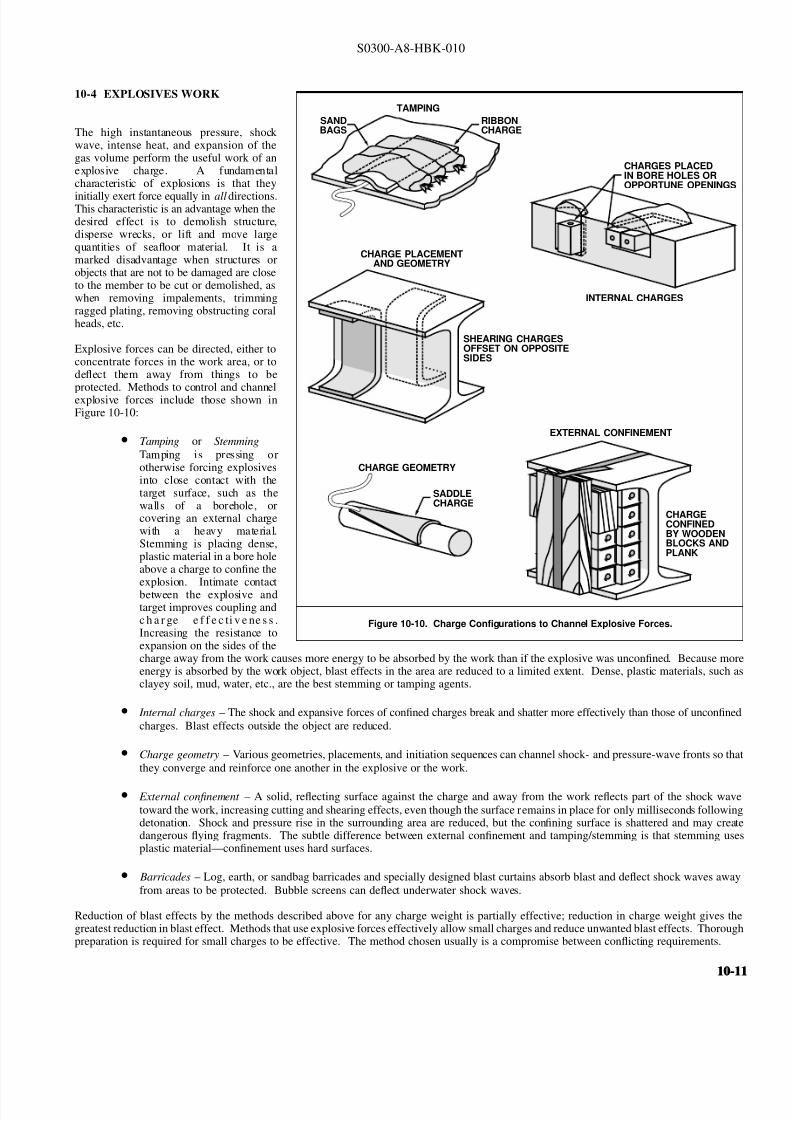
8132019 Articol despre explozii submarine
httpslidepdfcomreaderfullarticol-despre-explozii-submarine 1124
8132019 Articol despre explozii submarine
httpslidepdfcomreaderfullarticol-despre-explozii-submarine 1224
S0300-A8-HBK-010
10-41 Charge Weight Charge weight selection is based on two criteria
bull The charge must be large enough to perform the task
bull The charge must not be so large that it causes unacceptable damage to the casualty nearby structures or the environment
The minimum charge weight that will accomplish the task (in one shot) may be greater than the maximum charge weight what will not causedamage It is usually possible to perform the task in a series of steps each using charge weights smaller than the maximum acceptable weight
10-42 Underwater Blasting Water
Figure 10-11 Shared Charge Cutting Sequence
EXPLOSIVECHARGE
CONTAINER
LINER
CAVITY
SHAPEDCHARGE
(a)
S T A N D
- O F F
DETONA-TION WAVEAPPROACHESCAVITY LINER
(b)SHOCK WAVECOLLAPSESLINER INDUCINGJET FORMATION
(c)
CUTTING JETAPPROACHESTARGETSURFACE
(d) PLASTIC FLOW
IS INDUCED INTHE TARGETMATERIAL ANDTHE JET STARTSTO PENETRATE
(e)
JET PASSESTHROUGHTHE TARGET -CUT ISCOMPLETE
(f)
INITIATORpressure on the side of an object oppositethe explosive blast opposes the impact andexpansion of the explosive When the work involves moving large surface areasresistance to movement caused by waterpressure and hydrodynamic drag issignificant and explosive effectiveness isreduced For example it takes about onepound of explosive to break up and move acubic yard of rock in dry air Two to sixpounds of explosive per cubic yard arerequired to break and move the same rock underwater Explosive effectiveness is
further reduced as depth increases
Steel cutting by ribbon charges shapedcharges etc where little surface movementis required is not significantly affected byimmersion in water Shaped chargeeffectiveness is reduced if water cannot bedisplaced or evacuated from the cavity andstand-off (shaped charges are discussed inParagraph 10-421)
Most explosives detonate satisfactorilyunder water Some explosives containwater-soluble ingredients and aredesensitized with time when immersedunless sealed in waterproof containers
Certain explosives depend on dispersed microscopic air or gas bubbles for ease of initiation Immersion in deep water compresses the bubblesand renders them ineffective so they can be used only in shallow water or if specially formulated for deep water use Explosives dependingon dispersed bubbles for initiation include those based on or sensitized by nitroglycerine and nitroglycerol such as gelignites and blastinggelatins and those containing aqueous solutions of ammonium nitrate such as water gels and emulsions
Most military high explosives and commercial explosives based on PETN RDX and TNT can be used reliably in deep water because theyare not are not significantly water-soluble and do not depend on gas bubbles for initiation
Overlying water is an effective tamping agent but if the charge is not in intimate contact with the target the intervening water layer will largelynegate the tamping effect Even a thin water layer between the charge and target will dissipate some of the explosive energy before it reachesthe target The shock and compression waves pass through two media interfacesmdashexplosive to water and water to target energy is reflectedaway from the target at each interface If charges cannot be placed in intimate contact with the work additional tamping in the form of sandbags clay or soil should be used to overcome the dissipation of energy by the intervening water
Potential water tamping lends a slight theoretical advantage to blasting from the wet side of a hull but offsetting advantages accrue whenexplosives are placed in the dry
bull Explosives fuses and initiators are not subject to the desensitizing effects of water immersion or to disturbing forces of currentand surge
bull Charges can be placed more effectivelymdashit is easier to secure charges and intimate contact with the target surface can be attained
bull Charges and firing circuits can be inspected immediately before firing
bull There is greater control over the personnel placing explosives and their work can be monitored and inspected with less effort
Immersion time prior to firing should be minimized to reduce the desensitization of the explosives and the possibility that current or surge willdislodge charges or initiating circuits
10-1210-12
8132019 Articol despre explozii submarine
httpslidepdfcomreaderfullarticol-despre-explozii-submarine 1324
S0300-A8-HBK-010
10-43 Cutting and Fracturing Charges A principal use of explosives in salvage is cutting hull plating and structure in ships High-velocitybrisant explosives such as TNT and plastic explosives are best for cutting steel or aluminum Structural members are cut by a variety ocharges
bull Shaped charges ndash A lined or unlined cavity in the explosive produces a high-energy cutting jet
bull Fracturing charges ndash Specialized charge geometry causes convergence of strain waves in the target
bull Simple contact charges ndash Breakage is accomplished by the combined but uncoordinated effects of shock waves strain pulses angas expansion
Shaped and fracturing charges are far more efficient than contact charges and should be used when available and when suited to working conditions Because of their relatively small charge weights shaped and fracturing charges must be placed precisely and must be held in positioagainst current or surge to be effective If charges cannot be placed precisely better results may be obtained with less efficient contact charge
10-431 Shaped Charges A hollowed-
Figure 10-12 Typical Shaped Charges for Salvage Work
FLEXIBLE LINEARSHAPED CHARGE
BOX TYPELINEAR CHARGE
EXPLOSIVE
TARGET
CASE
METALLINER
ENCLOSED
STAND-OFFSPACE
CYLINDRICALCHARGE
EXPLOSIVECORE
DENSEFLEXIBLE
SHEATH
WOODENSPOOL
out or shaped charge detonated against ahard surface produces a crater that isapproximately a mirror image of the chargecavity The shaped charge is initiated at apoint behind the cavity the detonation waveexpands omnidirectionally from theinitiation point or axis Reaching the cavitythe detonation wave converges on a plane
(for linear charges) or axis (in cylindricalcharges) perpendicular to the target surfaceThe convergence of the shock waveconcentrates the explosive energy in a smallarea The resultant cratering is called the
Munro Effect If the charge is lined withmetal or other dense material the explosioncollapses the liner and carries it in the shock wave to the target surface as a slug (orblade) of metal and hot gas that acts as acutting jet The jet heats and erodes thetarget surface Shock-wave pressure and jeteffects combine to induce plastic flow in thetarget and cut through the material Figure10-11 illustrates the cutting sequence for alined shaped charge
For optimum effect shaped charges arepositioned at a stand-off distance from thetarget surface to allow the penetration jet toform completely before it reaches the targetsurface Optimum stand-off varies with thecavity angle and charge size stand-off isd et er m in ed f r om t ec hn ic al o rmanufacturerrsquos data for the charge used
Various-sized cylindrical shaped chargesare made for hole cutting Linear chargesare used for long cuts Linear charges areusually made in the form of a box with thecavity liner set across the inside of the boxas shown in Figure 10-12 Flexible linearshaped charges can conform to irregular
surfaces and cut lines Well-designedlinear cutting charges obtain good resultswith relatively small charge weightsIndividual charge weight and explosiversquosconsumption are based on data publishedfor the particular explosives used Data formilitary shaped charges is given in the Technical Manual for the Use of Explosives in Underwater Salvage (NAVSEA SW061-AA-MMA-010Typical manufacturerrsquos data for linear shaped charges are shown in Figure 10-13 (Page 10-14)
10-110-1
8132019 Articol despre explozii submarine
httpslidepdfcomreaderfullarticol-despre-explozii-submarine 1424
S0300-A8-HBK-010
Shaped charges can be improvised as
Figure 10-13 Typical Manufacturerrsquos Data for Linear Shaped Charges
STAND-OFF FOR OPTIMUM PERFORMANCE(RDX OR PETN EXPLOSIVE)
MINIMUM CUTTING PERFORMANCEAT OPTIMUM STAND-OFF
MINIMUM CUTTING PERFORMANCEAT OPTIMUM STAND-OFF
MINIMUM CUTTING PERFORMANCEAT OPTIMUM STAND-OFF
MINIMUM CUTTING PERFORMANCEAT OPTIMUM STAND-OFF
5
30 15
10
05
02
01
2010
JETCORDSTAND-OFFTARGET
05
02
01
05
0201
01
02
05
01
02
01
02
05
10
20
02
05
01
02
05
10
1 0
2 0
3 0
4 0
5 0
1 0 0
2 0 0
EXPLOSIVE CORELOAD GRAINSFOOT
EXPLOSIVE CORELOAD GRAINSFOOT
EXPLOSIVE CORELOAD GRAINSFOOT
EXPLOSIVE CORELOAD GRAINSFOOT
NOTE CUTS AT 7 AND 10 GRFTMADE AT ZERO STAND-OFF
EXPLOSIVE CORELOAD GRAINSFOOT
100
5
5
10
10
50 100 200 500 1000
20
20
50
50
100
100
200 500
200 500 1000 2000 5 0 0
S T A N D
- O F F I N C H E S
T H I C K
N E S S
C U T
I N
C H E S
T H I C K N E S S
C U T
I N
C H E S
T H I C K N E S S
C U T
I N
C H E S
T H I C K N E S S
C U T
I N
C H E S
1 0 0 0
2 0 0 0
A L U M
I N U M
S H E A
T H
C O P P
E R S H E A
T H
L E A D
S H E A
T H
C 1 0 1 8 S T E E
L T A R G
E T
COPPER-SHEATHEDJETCORD (RDX ORPETN EXPLOSIVE)
LEAD-SHEATHEDJETCORD (RDX ORPETN EXPLOSIVE)
2024-T351ALUMINUM
TARGET
C10118STEELTARGET
2024-T351ALUMINUM
TARGET
C10118STEELTARGET
ALUMINUM-SHEATHEDJETCORD (RDX
OR PETN EXPLOSIVE)
SILVER-SHEATHEDJETCORD
(DIPAMEXPLOSIVE)
CUT7075-T6
ALUMINUMTARGET
OPTIMUMSTAND-OFF
shown in Figure 10-14 When performance
data for a particular material is not
available cutting ability can be estimated
from the following
where
t = t o
ρρ
o
t = unknown cutting capacity
(thickness) in material of
density ρt o = known cutting capacity in
material of density ρo from
manufacturerrsquos data
Water in the stand-off and cavity prevents
the formation of the cutting jet Theenclosed stand-off of box-type shaped
charges excludes water but boxes can
withstand hydrostatic pressures only to
shallow depths that vary with the particular
unit For depths of 30 to 60 feet the stand-
off can be filled with closed-cell plastic
foam The foam inhibits jet formation
slightly so that performance is decreased
For deeper immersion the stand-off and
cavity must be constructed to withstand
hydrostatic pressure or made free flooding
and then evacuated with compressed air or
gas at depth For underwater use flexible
linear charges can be enclosed in flexibletubes filled with foam or evacuated by
compressed gas One manufacturer markets
a line of circular cutters prefabricated with
compressed gas fittings
10-432 Fracturing Charges A diamond-shaped sheet of plastic explosive laid on a steel plate and detonated simultaneously from two
opposite corners will fracture the metal along a line between the two uninitiated corners This effect is shown in Figure 10-15(a) The fracture
mechanism depends on the pressure rise as the shock waves from the two detonating points collide followed by the relaxation as the waves
pass through one another and the combined effect of two tension waves rebounding from the far side of the target This arrangement is a
diamond charge and is suitable for cutting bars and pipes but has limited application for plate cutting because the fracture extends only slightly
beyond the charge
The diamond charge principle was first applied to extended plate cutting in fracture tape Fracture tape shown in Figure 10-15(b) consists of
a series of diamond charges connected by continuous strips of explosive along the edges of the charges Fracture tape has seen only limiteduse because it was not manufactured in a flexible form The charge may fail to cut if bilateral asymmetry develops between the two initiation
trains Fracture tape can be improvised by cutting explosive sheet to the appropriate shape
Shock-wave refraction tape (SRT) is a recently developed explosive charge that works on the principle of shock-wave collision within metal
targets In this charge a continuous strip of explosive is molded to the back of an inert wave-shaping element as shown in Figure 10-15(c)
One manufacturer uses magnetic rubber as the wave-shaping element providing both flexibility as well as an attachment method (provided the
surfaces are clean and smooth) The performance of shock-wave refraction tape is comparable to that of shaped charges when cutting ordinary
steels very high strength fracture-resistant steels may not be cut as easily There is no cavity or stand-off to flood so SRT is more adaptable
to underwater use than linear shaped charges
10-1410-14
8132019 Articol despre explozii submarine
httpslidepdfcomreaderfullarticol-despre-explozii-submarine 1524
S0300-A8-HBK-010
Figure 10-14 Improvised Shaped Charges
SHEETEXPLOSIVE
STEEL ORALUMINUM
ANGLE
PLASTICEXPLOSIVE
PLASTICEXPLOSIVE
CONE
WINEBOTTLE
STICKS TAPEDTO SIDE ASSTAND-OFF
FUSE
CAP
S T A N D - O
F F
D I S T A N C E
FOOD CANWITH BOTHENDS CUT
OUTPLASTICEXPLOSIVE
SHEETMETALOR LEADSHEETCONE
RIVET
SIDES OFCAN FORMSTAND-OFF
CAP
80˚ - 90˚
Figure 10-15 Fracturing Charges
A
Arsquo
A ArsquoEXPLOSIVE
FRACTURE
EXPLOSIVESHOCK-WAVEFRONTS
REFLECTEDTENSION WAVE
(a) DIAMOND CHARGE (INITIATED AT POINTS A AND Arsquo)
(c) SHOCK-WAVE REFRACTION TAPE (SRT)(b) FRACTURE TAPE
EXPLOSIVE
INERT BARRIERSINITIATION POINT
EXPLOSIVE
WAVE-SHAPINGELEMENT
FRACTURES TENSIONWAVE
SHOCK WAVE
10-110-1
8132019 Articol despre explozii submarine
httpslidepdfcomreaderfullarticol-despre-explozii-submarine 1624
S0300-A8-HBK-010
10-433 Contact Charges Simple
Figure 10-16 Steel Cutting Contact Charges
DETONATINGCORD
EXPLOSIVE
STEEL PLATE
WELDS
STEELCHANNEL
STUD
PLATE
SECURINGSTRAP
EXPLOSIVESHEET OR
PLASTICEXPLOSIVE
contact charges require much heaviercharges than shaped or fracturing chargesExplosive performance can be increasedand charge weight reduced by carefulcharge placement confinement tampingand by scoring cut lines with cuttingtorches or mechanical cutters Some
effective charge placements and geometryare shown in Figure 10-16
Charge weights can be estimated from thefollowing relationships
where
W = 3
8 A Structural steel
W = D 2 High carbon or alloy steel
W = charge weight lbs TNT
A = cross-sectional area of sectionto be cut in2
D = diameter or thickness of section to be cut in
To determine charge weights for explosivesother than TNT the TNT charge weight isdivided by the relative effectiveness (RE)factor
10-434 Charge Placement Cutting charges are most effective when the cut line is adjacent to but not on a rigid portion of the target surfaceThe target must be restrained from moving away from shaped and fracturing charges so the explosive energy is expended in cutting or fracturingthe target rather than pushing it away Contact charges create a strong shearing action along the line between the movable and rigid surfaceHull cutting charges are most effective when slightly offset from frames
bull If placed in the middle of the span a large portion of the explosive energy is expended in deflecting the plate
bull If placed directly over a stiffener both the stiffener and the plate must be cut
For efficient cutting charges must be placed in intimate contact with the target surface Charges must be secured to all vertical steeply angledand overhead surfaces and to horizontal surfaces where current wind vibration or target movement may dislodge them Where no tie-downpoints exist the following securing methods can be used
bull Light metal straps bolted to studs explosively set or friction welded along each side of the cut line
bull Tie-down wires lines or bongee cords inserted through holes cut drilled or burned through the plating (tie-downs can also beled to studs or magnetic clamps)
bull Sandbags or similar weights placed on charges on horizontal surfaces
bull Backing charges with magnetic strips adhesive strips or small suction pads (these methods have had limited success)
bull Hose charges can be stretched between tie-down points over flat or smoothly convex surfaces
10-435 Ship Sectioning Explosives are commonly used to section wrecks for piecemeal removal or to separate a casualty into two piecesso that one part can be salvaged Ship sectioning including explosive methods is discussed in the US Navy Ship Salvage Manual Volume 2(S0300-A6-MAN-020) The following notes supplement that discussion
10-1610-16
8132019 Articol despre explozii submarine
httpslidepdfcomreaderfullarticol-despre-explozii-submarine 1724
S0300-A8-HBK-010
When cutting a ship transversely the internal structure must be cut as well as the more accessible hull plate and stiffeners It is very difficu
to obtain complete separation in a single shot Salvors should plan to make cuts in several shots or have thermal or mechanical cutting gea
available to sever stubborn structure
In a landmark operation in 1973 the salvageable aft section of a 960-foot laden ore carrier was explosively separated from the forward part o
the ship which was abandoned The ship had sunk by the bow in 130 feet of water With holds 7 8 9 and 10 their associated wing and
double-bottom tanks and the machinery spaces dry the after section was buoyant and afloat The hull was cut in way of number 7 hold b
more than 1800 feet of custom engineered and fabricated high speed explosive cutters All cutters were placed in the dry number 7 wing anbottom tanks Instantaneous separation (necessary to prevent capsize of or damage to the aft section) was attained by
bull Placing cutters against all bulkheads shell plating stringers void tank sections and pipes extending through the transvers
bulkhead separating holds 7 and 8
bull Taking advantage of the vertical shear on the hull resulting from the weight of the forward section laden with 90000 tons of ore
and the buoyancy of the after section and
bull Maintaining a 300-ton horizontal astern pull on the after section as the cutters were detonated
Blast curtains were rigged in the number 7 tanks and hold and the number 8 wing and bottom tanks were pressurized with compressed air to
protect the separating bulkhead A diverrsquos survey after the successful separation revealed no damage to the bulkhead The operation was mad
possible by the salvorsrsquo employment of specialist explosives engineers who custom designed the explosive cutters taking into account permissiblblast effects on the aft number 7 bulkhead gas generation and dispersion requirements mutual interference between charges and the strength
of hull structural members See The Cutting of the Igara in Reedrsquos Commercial Salvage Practice for a more detailed discussion of th
operation
The order in which the different members are to be cutmdashas well as the methods to be usedmdashmust be considered carefully Preliminary cut
should not weaken the structure to the point that it is in danger of collapsing and injuring personnel placing charges for subsequent cuts
Cutting methods are frequently combined A hull can be opened up with explosives to permit access to internal structure to be cut by mechanica
or thermal methods In some cases preparatory weakening cuts are made by divers with oxy-arc or exothermic torches with the final cuts mad
explosively
Simple types of ships are better candidates for explosive sectioning than more complex types The following ship types lend themselves t
explosive sectioning
bull Transversely framed ships because there are fewer longitudinal stiffeners to cut
bull Freighters and bulk carriers because most do not have centerline longitudinal bulkheads (some bulk carriers have wing tanks whos
inner bulkheads must be cut) Small ships often do not have double bottoms
bull Small single-product tankers because they do not have wing tanks or double bottoms
The following ship types are not good candidates for explosive sectioning
bull Longitudinally framed ships because of the large number of longitudinal stiffeners
bull Passenger ships and warships because of their extensive joiner work internal subdivision wireways piping and ventilatio
systems
bull Large tankers and product carriers because they are constructed with two or more longitudinal bulkheads
bull Freighters with insulated holds
10-110-1
8132019 Articol despre explozii submarine
httpslidepdfcomreaderfullarticol-despre-explozii-submarine 1824
S0300-A8-HBK-010
10-44 Seafloor Blasting Seafloor
Figure 10-17 Obstruction Blasting
CONTACT BLASTING MUDCAPPING
SNAKEHOLING
STEMMINGSTEMMING
CHARGE
CHARGE
BLOCKHOLING
blasting moves large amounts of seafloor
material by channeling trenching etc or
removes isolated obstructions such as
pinnacles coral heads and boulders The
basic techniques are
bull Contact Blasting ndash Chargesare placed on the formation
to be blasted either indi-
vidually or in line or
checkerboard patterns The
detonating explosive imparts
a violent blow to the seafloor
material The efficiency of
contact blasting depends on
maintaining intimate contact
with the material to be
blasted Contact blasting is
the least efficient blasting
method in terms of explosive
consumption but requires the
least time and effort to
prepare and set charges
bull Boreholes ndash Internal charges
are placed in boreholes
drilled or augured into the
object or strata to be blasted
10-441 Rock Blasting The choice of explosive for a particular rock-blasting job depends on the hardness and density of the rock and the
type of breakage desired Fast brisant explosives such as TNT or composition C-4 are required to break most kinds of rock although slower
explosives are effective on soft rock such as limestone
Rock is weakest in tension so internal charges are most effective Contact blasting depends on the tamping effect of overlying water to confine
the explosion momentarily and is effective only on soft rock and coral where the material is broken by crushing rather than shattering The
rock fragments are moved by the expanding gases so high gas production is required to move dense rock If the object is to break up rock for
removal by nonexplosive means gas production of the explosive is less important Individual boulders are broken by one of the methods
discussed below The methods are illustrated in Figure 10-17
bull Mudcapping ndash A contact charge is covered with 10 to 12 inches of mud clay or moist soil tamping Plastic clay is the most
effective tamping Loose sand should not be used but sandbags are effective
bull Snakeholing ndash The charge is placed in a hole jetted bored or otherwise excavated under an object lying on or partially buried
in a soft seafloor Snakeholing is more effective than mudcapping under all conditions and requires about one-half as much
explosive as contact blasting
bull Blockholing ndash The charge or charges are placed in one or more boreholes Explosive effect can be altered by changing charge
weights and placement rock formations boulders concrete structures etc can be completely demolished be broken into
fragments of varying size or have portions broken off Blockholing requires about one-third as much explosive as contact blasting
Table 10-4 gives approximate explosive requirements in pounds per
Table 10-4 Powder Factors (lbyd3) for Rock Blasting
Blas ting Metho d A ir B la sting Und erwater Blas ting
Contact Blasting Not effective 6 - 20
Mudcapping 1 - 2 4 - 15
Snakeholing 1 - 11 frasl 2 3 - 10
cubic yard or powder factor for different rock-blasting methods A
range of powder factors for each method is given The actual powder
factor for any project will depend on
bull The relative density and toughness of the rock
bull Whether individual boulders or massive rock formations
are being blasted
bull Water depth
10-1810-18
8132019 Articol despre explozii submarine
httpslidepdfcomreaderfullarticol-despre-explozii-submarine 1924
S0300-A8-HBK-010
The lower values in Table 10-4 are based
Table 10-5 Rock Density and Toughness
Type of Rock Density lbft3 Relative Toughness (Limestone = 1)
Andesite 150 - 175 11
Basalt 150 - 200 17 - 23
Conglomerate 125 - 162 NA
Dioritic 156 - 200 19 - 21
Felsite 150 - 200 NA
Gabbro 169 - 200 NA
Granite 156 - 194 15 - 21
Gneiss 150 - 181 10 - 19
Limestone 160 - 187 10
Marble 131 - 181 NA
Quartzite 125 - 200 19 - 27
Sandstone 124 - 194 15 - 26
Schist 150 - 175 10 - 21
Shale 112 - 194 NA
Slate 156 - 194 12
on blasting massive limestone at depths of 30 to 60 feet Values high in the range areused with tougher or denser rocks andgreater depth Lower values are used whenblasting individual boulders or outcrop-pings Table 10-5 compares densities andtoughness of common rocks
Rock blasting by internal charges is mosteffective when there is a free face approxi-mately parallel to the borehole Thedetonation of the explosive creates a highgas pressure in the charge hole generating acompressive strain pulse in the surroundingrock The compressive pulse travels outwardin all directions Near the hole theamplitude of the strain pulse is sufficient tocrush the rock Amplitude decays rapidly asthe pulse travels outward until it can nolonger crush the rock The pulse travels out-ward until it is reflected from a free surfaceas a tensile strain pulse As rock is much
Figure 10-18 Excavation Rock Blasting
DRILLING FACE
WORKING OR FREE FACE
BOREHOLE
BENCH
EXCAVATION FLOOR(PROJECT DEPTH)
L
B
BltL
INSUFFICIENT EXPLOSIVEENERGY RELEASE AT
BOTTOM OF HOLE
B
MAINFRACTURELINES
COLUMN LOADEDHOLE
45˚
STRESS PATTERN FOR ACONCENTRATED CHARGE
IN BOTTOM OF HOLE
REFLECTEDTENSION WAVE
UNREFLECTEDCOMPRESSIONWAVE
TOE
weaker in tension than compression the
tensile pulse is able to break the rock pro-gressing from the free face back towards thecharge hole The expanding gases in thecharge hole are not directly responsible formuch of the rock breakage to some extentthe rock is pulled apart rather than pushedapart
Blasting massive seafloor rock formations issubject to constraints similar to those en-countered in quarry blasting and similarmethods are employed Detailed informationon rock blasting is found in publications onmining and quarrying For effective blastingit is necessary to establish a breaking orworking face at an angle to the drilling faceThe drilling face is most often the horizontalseafloor the working face is vertical orinclined from the vertical by an angle of 45degrees or less The working face is brokenback in steps by detonating charges in rowsof holes behind the face For cuts deeperthan the maximum practical drilling depththe working face is broken back in stages byestablishing intermediate floor levels orbenches as shown in Figure 10-18
A working face can be established in aflush surface by blasting out a crater with asingle charged hole cluster of holes or lineof holes Empty relief holes between andaround charged holes provide free faces toreflect strain pulses and space for displaced
rock to move into The excavation floorand work face can be squared up bysubsequent blasting
Boreholes can be drilled by diver-operated jackhammers or rock drills for smalloperations For extensive drillingoperations a spud-moored drill barge or asubmersible crawler-mounted rock drillshould be used
10-110-1
8132019 Articol despre explozii submarine
httpslidepdfcomreaderfullarticol-despre-explozii-submarine 2024
S0300-A8-HBK-010
10-442 Coral Blasting Coral is difficult
Figure 10-19 Coral Blasting
13
13
12
12
11
11
10
10
9
9
8
8
7
7
6
6
5
5
4
4
3
3
2
2
1
1
0
0
DEPTH AND WIDTH OF CUTS MADE IN CORAL WHEN BLASTING WITH CAVITY CHARGES
DEPTH AND WIDTH OF CUTS MADE IN CORAL BY STANDARDUS MARK 8 DEMOLITION CHARGES
VOLUME OF CORAL REMOVED USING9-KG (20 POUND) CHARGES
CRATER WIDTH IN FEET
CRATER WIDTH IN FEET
NUMBER OF PACKS
V O L U M E
I N
C U B I C
F E E T
1 2 3 4 5
1
1
2
2
3
3
4
4
5
5
6
6
7
7
8
8
9
9
10
10
11
11
12
12
13
13
1
1
2
2
3
3
4
4
5
5
100
20
30
40
50
60
70
80
90
100110
D E P T H
I N
F E E T
D E P T H
I N
F E E T
to blast because of its porosity High-velocity explosives have been successfulbut slow-detonating explosives are moreeffective Coral will clog rock drills sointernal charges are set in powder points(pipes driven into the formation) Powderfactors for coral are about five pounds per
cubic foot for mushroom-shaped coralheads and higher for solid headsDemolition of an above-water coralformation requires about three times asmuch explosive as an equivalent underwaterformation unless a well-placed thoroughlytamped internal charge is used Linecharges can be used to cut trenches orchannels in coral Figure 10-19 showstypical results of coral blasting
10-443 Blasting ImpalementsRemoving an impaling rock or coral head isa slow and tedious process The chargesmust be large enough to break the rock orcoral but light enough that they do not
damage the ship or drive the impalementfurther into the ship The only feasibleprocedure is to begin with very smallcharges and check the results after eachshot Charge size can be increasedincrementally if there is no hull damage orthe same charge can be repeated until theimpalement is gradually severed or brokenaway A large internal concrete patch overthe impalement and surrounding platingstrengthens the hull against shock loadingso that larger charges can be used Theimpalement should be cut off about twofeet below the hull
When external access to the impalement isdangerous or impossible the impalement isattacked from the inside The bestprocedure is to use small charges inshallow boreholes with interspersed relief holes to progressively shatter theimpalement and lower it sufficiently toclear the hull Doors and hatches should beopen during blasting to prevent the hull from being pressurized internally by the explosive gases It may be necessary to build a trunk aroundthe impalement to provide a watertight enclosure and to vent explosive gases to the atmosphere
10-444 Setting Anchors Anchors can be set in hard pan coral clay or mud bottoms with explosives Small charges are set near the anchoras shown in Figure 10-20 and detonated The anchor is lifted and dropped into the blast crater At the same time a quantity of loose or brokenseafloor is lifted out of the crater and some of this material will settle on the anchor Anchors can be explosively settled into seafloors subjectto liquefication under high-frequency cyclic loading such as clean medium- or low-density cohesionless soils A number of small chargesdetonated sequentially on short delay in the vicinity of the anchor can liquefy the soil allowing the anchor to settle into the seafloor underits own weight
10-445 Channeling in Soft Bottoms Military dynamite or other low-velocity low-brisance explosives are best for moving soft plasticmaterial Powder points contact charges charges in augured or excavated holes or hose charges in checkerboard or linear patterns are usedContact blasting will normally dig a channel or crater four to five feet deep Deeper cuts can be attained by driving powder points to the desiredchannel depth plus the distance between points Powder factors are three to five pounds of explosive per cubic yard of soil Alternate pointsshould contain charges of different weights so that the detonation waves do not cancel one another Soft seafloors are almost always excavatedmore effectively by nonexplosive means such as dredging or scouring
10-2010-20
8132019 Articol despre explozii submarine
httpslidepdfcomreaderfullarticol-despre-explozii-submarine 2124
S0300-A8-HBK-010
10-45 Concrete and Masonry Blasting
Figure 10-20 Setting Anchors with Explosive Charges
CHARGESANCHOR
FIRING SYSTEM BLASTING CAP
BUOY
DETONATING CORD MADEUP TO WORKING LINE
LIGHT LINE TO KEEP STRAINOFF DETONATING CORD
Concrete and masonry are blasted by thesame methods as rock Simple concretedispersal requires about one pound of explosive per cubic foot Breachingcharges for concrete and masonry structuresare estimated by
W = R
3
KC where
W = charge weight lbs TNT R = breaking radius ft
= thickness for externalcharges
= distance to outside surfacefor internal charges
K = material factor from Table10-6
C = tamping factor from Figure10-21 (Page 10-22)
10-46 Timber and Pile Cutting Forcutting timber high-velocity brisant
explosives work best but low-velocityexplosives are effective when appliedproperly Charge weights vary as thesquare of the diameter of the timberEmpirical relationships for determiningcharge weights are given below
where
W = D 2
4Untamped external charges
W = D 2
250Tamped internal charges
Table 10-6 Material Factor K for Concrete Breaching Charges
Material R K
Poor masonry shale and hardpan All values 0225
Good masonry ordinary concrete rock
Less than 3 ft
3 to 5 ft
5 to 7 ft
More than 7 ft
035
0275
025
0225
Dense concrete first-class masonry
Less than 3 ft
3 to 5 ft
5 to 7 ft
More than 7 ft
045
0375
0325
0275
Reinforced concrete (concrete only will
not cut reinforcing steel)
Less than 3 ft
3 to 5 ft
5 to 7 ft
More than 7 ft
070
055
050
0425
W = charge weight lbs TNT D = diameter of round or leastdimension of dressedtimber in
For explosives other than TNT chargeweight is determined by dividing the TNTcharge weight by the relative effectiveness(RE) factor
10-47 Reducing Underwater ShockWave Pressure and Impulse Shock waves damage structures by two differentmechanisms
bull The peak shock wave pressureexceeds the compressive strengthof the material
bull The impulse causes structural elements to vibrate with their natural frequency The deflection may be great enough to cause damageImpulse caused vibrations can cause damage even when the peak pressure does not exceed the compressive strength of the material
Shock wave pressure or impulse at a structure can be reduced by charge placement bubble screens and in the case of multiple charges firingsequence
10-210-2
8132019 Articol despre explozii submarine
httpslidepdfcomreaderfullarticol-despre-explozii-submarine 2224
S0300-A8-HBK-010
10-471 Charge Placement Observations
Figure 10-21 Tamping Factor C for Concrete Breaching Charges
C = 45
C = 25 C = 20 - 25
C = 23C = 35
C = 20 C = 15
C = 25
UNTAMPED CHARGES
TAMPED CHARGES
R
R R
R
R
R R
R
t 03tltdltt
D
C = 125C = 125
STEMMED PLACED IN
CENTER OFMASS
C = 125 - 10
R
t dgtt
DR
R
FILL
Figure 10-22 Shock Wave Effects for Various Blasting Conditions
NOTE
620PSI
50PSI
29PSI
14 MS
13 MS
2 MS
(a) 33 FT FROM 1LB CHARGEIN FREE WATER
EXTRAPOLATED FROM DATAFOR POINT 47 FT FROM 3LBCHARGE IN FREE WATER
NOTEEXTRAPOLATED FROM DATAFOR POINT 47 FT FROM 2LBCHARGE IN 29 FT3 OF ROCK
(b) 33 FT FROM 1LBCHARGE IN ROCK
(c) 33 FT FROM 1LB CHARGEIN FREE WATER THROUGHBUBBLE SCREEN(0043 FT3SEC PER FT)
of underwater rock blasting operations haveshown that peak pressures for explosiveswell packed in bore holes is much less thanthat of charges in the water Figure 10-22compares time pressure curves 33 feet froma one pound charge in free water and thesame sized charge in submerged rock Thegreat difference in peak pressures and totalimpulse indicates that a principal means of reducing underwater shock wave effects isto ensure that charges are not detonated whileexposed to free water In seafloor orobstruction blasting internal charges shouldbe used The top portions of boreholes fora distance of 15 times the borehole diametershould be left uncharged Blasting patternsshould be arranged to avoid sympatheticdetonation and ensure that charges to bedetonated later in a firing sequence are notexposed by rock breakage from earlierdetonations Heavy sandbag or clay tampingover cutting charges can significantly reduceshock effects in the surrounding area
10-472 Bubble Screens An impingingshock wave compresses the bubbles of abubble screen over a period of somemilliseconds On their subsequent re-expansion over a period of milliseconds thebubbles emit new compression waves withlower peak values The part of the shock wave that passes between the bubbles isalso attenuated Increasing the number of air bubbles increases the reduction in peak pressure but also increases the duration of the pressure on the side of the bubblescreen away from the blast Investigationsby AT Edwards at the Hydro-electricPower Commission of Ontario showed thatthe peak pressure 33 feet from a one poundcharge was reduced by a factor of 10 by anintervening bubble screen produced by anair flow of 0043 cubic feet per second perfoot of pipe Doubling the air flow reducedpeak pressure by a factor of 70 at the samedistance with the same charge weight At164 feet the corresponding reductionfactors were 8 and 40 Three inchdiameter pipe was used in the experimentswith groups of two diametrically opposite1 frasl 16-inch holes spaced 3 frasl 4-inch or 11 frasl 2 inchesapart Figure 10-22 shows the pressure-time history 33 feet from a one poundcharge with an intervening water curtain
In reducing peak pressure while simultan-eously extending the decay time the bubble
screen redistributes but does not decrease to-tal impulse Bubbles screens are ineffectivein preventing damage in most cases wherethe damage mechanism is primarily impulse
10-473 Firing Sequence In multiple-charge shot-delay shots firing the chargesclosest to the structure to be shielded firstwill reduce the impulse transmitted to thestructure by the delayed charges Theimpulse from the delayed charges is partlyscreened off by explosion gases (and brokenrock when seafloor blasting) from earliercharges
10-2210-22
8132019 Articol despre explozii submarine
httpslidepdfcomreaderfullarticol-despre-explozii-submarine 2324
S0300-A8-HBK-010
10-5 PERMITS
Authorization from the appropriate fleet commander is required for all underwater explosives detonations OPNAVINST 85302 lists the basi
requirements to be met before using demolitions Amplifying instructions in the 8530 series have been issued by fleet commanders
Some of the additional permits required from various Federal and local agencies are described in the following paragraphs It may take man
months to obtain all the required permits Planning for explosives operations should start well in advance and be coordinated carefully so thaall permits are valid over the desired time frame and that other salvage tasks that proceed sequentially or concurrently with the explosive
operations are ready on schedule
10-51 Corps of Engineers Section 10 of the River and Harbor Act of March 3 1899 (30 Stat 1151 33 USC 403) prohibits the obstructio
or alteration of any navigable water of the United States without authorization from the Secretary of the Army Requirements for and limitation
of permits are described in Title 33 of the US Code of Federal Regulations (33 CFR) Article 209120 Detailed information concerning th
permits required for a specific project can be obtained from the local Corps of Engineers Office or from the Department of the Army Offic
of the Chief of Engineers Washington DC 20314
10-52 Environmental Impact Statement Explosives projects that may have an adverse effect on the environment may require the filing o
an Environmental Impact Statement Information on the filing of the statement is found in OPNAVINST 50901 (series)
10-53 State and Local Agencies The number and kind of permits required for explosives operations varies widely from location to location
A partial listing of agencies that may require permits includes
bull State Fish and Game Commission
bull State Lands Commission
bull State Oil and Gas Commission
bull StateEnvironmental Commission Department of Environmental ManagementEnvironmental Protection Agency or similar agency
bull County Board of Supervisors
bull Local police or sheriff
bull Fire Marshal
bull City Engineer
10-6 OPERATIONAL NOTES
10-61 Test Shots Because of the imprecise nature of charge weight and blast effect calculations test shots should always be made before
or at the beginning of an explosives job Test shots are made to determine two quantities
bull The minimum charge weight required to perform the task
bull The maximum charge weight that will not cause unacceptable damage to the casualty nearby structures or the environment
Tests to determine minimum charge weight should be conducted well before the operation at an explosives range or remote site
The maximum acceptable charge weight is estimated by calculation and verified by on-site test shots Test shots are usually conducted as th
first working shots Test shots start with charges lighter than those calculated for the job gradually increasing the charge weights until th
minimum charge weight to perform the task is reached or blast effects become unacceptable
10-210-2
8132019 Articol despre explozii submarine
httpslidepdfcomreaderfullarticol-despre-explozii-submarine 2424
S0300-A8-HBK-010
10-62 Explosives Expertise The importance of seeking the advice of experienced hands for explosives projects cannot be overemphasized
There is no program in the US Navy to train or certify salvage demolitions specialists Navy first class divers and diving officers receive
limited explosives demolitions training Explosive ordnance disposal (EOD) divers and special warfare swimmers (SEAL) receive additional
training in specialized procedures that are not always applicable to salvage The particular demolitions expertise of a Navy diver is a function
of on-the-job experience that may vary from extensive to none In the absence of personnel experienced in salvage demolitions advice may
be sought from Navy Mobile Construction Battalions or the Army Corps of Engineers Commercial explosives consultants may be retained
through the Supervisor of Salvage
10-63 US Military Explosives A wide variety of explosives in various types of demolition charges are maintained in the system for use
by military forces These explosives and charges are described in the Navy technical manuals Use of Explosives in Underwater Salvage
(NAVSEA-SW061-AA-MMA-010) and Demolition Materials (NAVSEA OP 2212) and the Army field manual Explosives and Demolitions (FM
5-25) A summary of the characteristics of US Military explosives is given in Table 10-7
Table 10-7 Characteristics of Military Explosives
Explosive Typical Uses
Rate of Detonation
(Feet per Second)
Relative Effectiveness as
an External Charge
(TNT = 100)
Intensity of
Toxic Fumes
Water
Resistance
Amatol Bursting Charge 16000 fps 117 Dangerous Poor
Ammonium Nitrate Cratering Charge and
Composition Explosives 8900 fps 042 Dangerous None
Black Powder Time Blasting Fuse 1300 fps 055 Dangerous None
Composition A-3 Booster Charge and Bursting
Charge 26500 fps 126 Dangerous Good
Composition B Bursting Charge 25600 fps 135 Dangerous Excellent
Composition C-3 Demolition Charge 25000 fps 126 Dangerous Good
Composition C-4 Demolition Charge 26500 fps 126 Dangerous Excellent
HBX-1 and HBX-3 Demolition Charge 24300 fps Air 148
Underwater 168 Dangerous Excellent
H-6 Demolition Charge 24300 fps Air 148
Underwater 168 Dangerous Excellent
Pentolite 5050
Booster Charge and Bursting
Charge 24600 fps 126 Dangerous Excellent
PETN Detonating Cord Blasting Cap
and Demolition Charge 26000 fps 166 Dangerous Excellent
RDX Blasting Caps Composition
Explosives 27400 fps 160 Dangerous Excellent
Tetryl Booster Charge and
Composition Explosives 23300 fps 125 Dangerous Excellent
Tetrytol 7525 Demolition Charge 23000 fps 120 Dangerous Excellent
TNT Demolition Charge and
Composition Explosives 22500 fps 100 Dangerous Excellent
TNT is used as the standard (TNT = 100) for comparison of the effectiveness of other explosives
10-64 Commercial Explosives A variety of commercial explosives and explosive devices are available including highly effective custom-
made steel cutting charges liquid explosives gelatins etc The Supervisor of Salvage should be contacted if the use of commercial explosives
is indicated
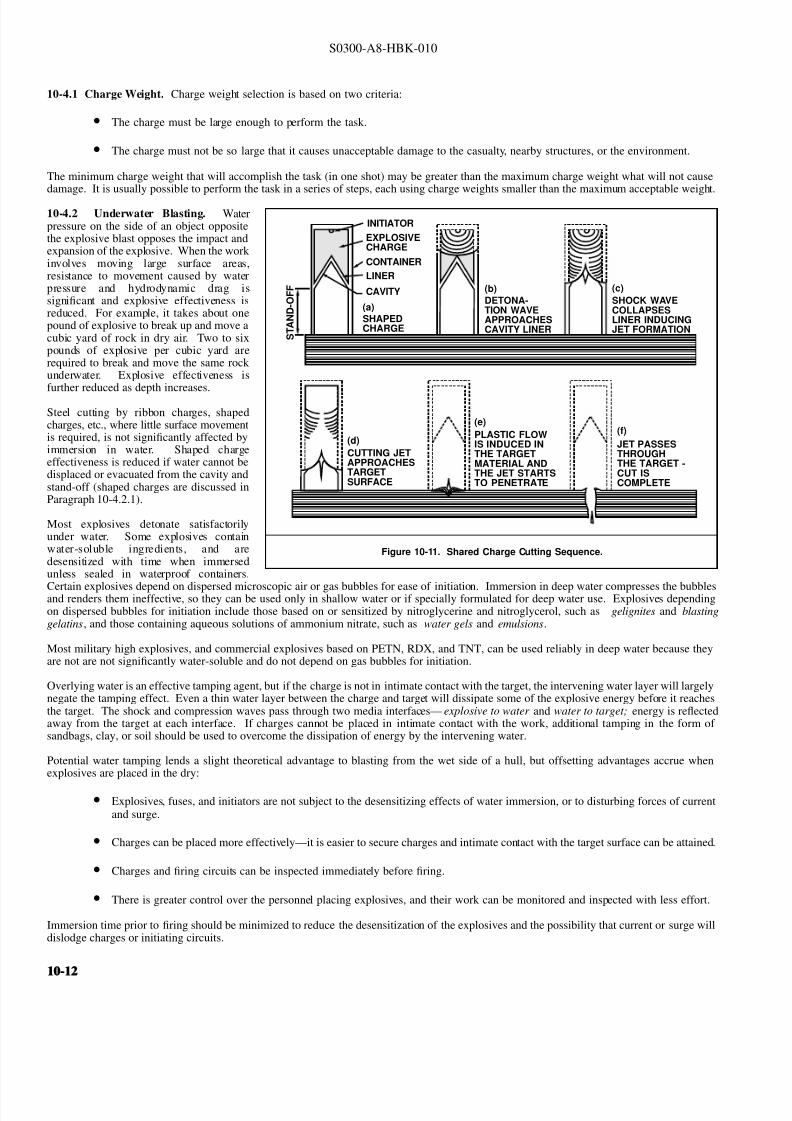
8132019 Articol despre explozii submarine
httpslidepdfcomreaderfullarticol-despre-explozii-submarine 1224
S0300-A8-HBK-010
10-41 Charge Weight Charge weight selection is based on two criteria
bull The charge must be large enough to perform the task
bull The charge must not be so large that it causes unacceptable damage to the casualty nearby structures or the environment
The minimum charge weight that will accomplish the task (in one shot) may be greater than the maximum charge weight what will not causedamage It is usually possible to perform the task in a series of steps each using charge weights smaller than the maximum acceptable weight
10-42 Underwater Blasting Water
Figure 10-11 Shared Charge Cutting Sequence
EXPLOSIVECHARGE
CONTAINER
LINER
CAVITY
SHAPEDCHARGE
(a)
S T A N D
- O F F
DETONA-TION WAVEAPPROACHESCAVITY LINER
(b)SHOCK WAVECOLLAPSESLINER INDUCINGJET FORMATION
(c)
CUTTING JETAPPROACHESTARGETSURFACE
(d) PLASTIC FLOW
IS INDUCED INTHE TARGETMATERIAL ANDTHE JET STARTSTO PENETRATE
(e)
JET PASSESTHROUGHTHE TARGET -CUT ISCOMPLETE
(f)
INITIATORpressure on the side of an object oppositethe explosive blast opposes the impact andexpansion of the explosive When the work involves moving large surface areasresistance to movement caused by waterpressure and hydrodynamic drag issignificant and explosive effectiveness isreduced For example it takes about onepound of explosive to break up and move acubic yard of rock in dry air Two to sixpounds of explosive per cubic yard arerequired to break and move the same rock underwater Explosive effectiveness is
further reduced as depth increases
Steel cutting by ribbon charges shapedcharges etc where little surface movementis required is not significantly affected byimmersion in water Shaped chargeeffectiveness is reduced if water cannot bedisplaced or evacuated from the cavity andstand-off (shaped charges are discussed inParagraph 10-421)
Most explosives detonate satisfactorilyunder water Some explosives containwater-soluble ingredients and aredesensitized with time when immersedunless sealed in waterproof containers
Certain explosives depend on dispersed microscopic air or gas bubbles for ease of initiation Immersion in deep water compresses the bubblesand renders them ineffective so they can be used only in shallow water or if specially formulated for deep water use Explosives dependingon dispersed bubbles for initiation include those based on or sensitized by nitroglycerine and nitroglycerol such as gelignites and blastinggelatins and those containing aqueous solutions of ammonium nitrate such as water gels and emulsions
Most military high explosives and commercial explosives based on PETN RDX and TNT can be used reliably in deep water because theyare not are not significantly water-soluble and do not depend on gas bubbles for initiation
Overlying water is an effective tamping agent but if the charge is not in intimate contact with the target the intervening water layer will largelynegate the tamping effect Even a thin water layer between the charge and target will dissipate some of the explosive energy before it reachesthe target The shock and compression waves pass through two media interfacesmdashexplosive to water and water to target energy is reflectedaway from the target at each interface If charges cannot be placed in intimate contact with the work additional tamping in the form of sandbags clay or soil should be used to overcome the dissipation of energy by the intervening water
Potential water tamping lends a slight theoretical advantage to blasting from the wet side of a hull but offsetting advantages accrue whenexplosives are placed in the dry
bull Explosives fuses and initiators are not subject to the desensitizing effects of water immersion or to disturbing forces of currentand surge
bull Charges can be placed more effectivelymdashit is easier to secure charges and intimate contact with the target surface can be attained
bull Charges and firing circuits can be inspected immediately before firing
bull There is greater control over the personnel placing explosives and their work can be monitored and inspected with less effort
Immersion time prior to firing should be minimized to reduce the desensitization of the explosives and the possibility that current or surge willdislodge charges or initiating circuits
10-1210-12
8132019 Articol despre explozii submarine
httpslidepdfcomreaderfullarticol-despre-explozii-submarine 1324
S0300-A8-HBK-010
10-43 Cutting and Fracturing Charges A principal use of explosives in salvage is cutting hull plating and structure in ships High-velocitybrisant explosives such as TNT and plastic explosives are best for cutting steel or aluminum Structural members are cut by a variety ocharges
bull Shaped charges ndash A lined or unlined cavity in the explosive produces a high-energy cutting jet
bull Fracturing charges ndash Specialized charge geometry causes convergence of strain waves in the target
bull Simple contact charges ndash Breakage is accomplished by the combined but uncoordinated effects of shock waves strain pulses angas expansion
Shaped and fracturing charges are far more efficient than contact charges and should be used when available and when suited to working conditions Because of their relatively small charge weights shaped and fracturing charges must be placed precisely and must be held in positioagainst current or surge to be effective If charges cannot be placed precisely better results may be obtained with less efficient contact charge
10-431 Shaped Charges A hollowed-
Figure 10-12 Typical Shaped Charges for Salvage Work
FLEXIBLE LINEARSHAPED CHARGE
BOX TYPELINEAR CHARGE
EXPLOSIVE
TARGET
CASE
METALLINER
ENCLOSED
STAND-OFFSPACE
CYLINDRICALCHARGE
EXPLOSIVECORE
DENSEFLEXIBLE
SHEATH
WOODENSPOOL
out or shaped charge detonated against ahard surface produces a crater that isapproximately a mirror image of the chargecavity The shaped charge is initiated at apoint behind the cavity the detonation waveexpands omnidirectionally from theinitiation point or axis Reaching the cavitythe detonation wave converges on a plane
(for linear charges) or axis (in cylindricalcharges) perpendicular to the target surfaceThe convergence of the shock waveconcentrates the explosive energy in a smallarea The resultant cratering is called the
Munro Effect If the charge is lined withmetal or other dense material the explosioncollapses the liner and carries it in the shock wave to the target surface as a slug (orblade) of metal and hot gas that acts as acutting jet The jet heats and erodes thetarget surface Shock-wave pressure and jeteffects combine to induce plastic flow in thetarget and cut through the material Figure10-11 illustrates the cutting sequence for alined shaped charge
For optimum effect shaped charges arepositioned at a stand-off distance from thetarget surface to allow the penetration jet toform completely before it reaches the targetsurface Optimum stand-off varies with thecavity angle and charge size stand-off isd et er m in ed f r om t ec hn ic al o rmanufacturerrsquos data for the charge used
Various-sized cylindrical shaped chargesare made for hole cutting Linear chargesare used for long cuts Linear charges areusually made in the form of a box with thecavity liner set across the inside of the boxas shown in Figure 10-12 Flexible linearshaped charges can conform to irregular
surfaces and cut lines Well-designedlinear cutting charges obtain good resultswith relatively small charge weightsIndividual charge weight and explosiversquosconsumption are based on data publishedfor the particular explosives used Data formilitary shaped charges is given in the Technical Manual for the Use of Explosives in Underwater Salvage (NAVSEA SW061-AA-MMA-010Typical manufacturerrsquos data for linear shaped charges are shown in Figure 10-13 (Page 10-14)
10-110-1
8132019 Articol despre explozii submarine
httpslidepdfcomreaderfullarticol-despre-explozii-submarine 1424
S0300-A8-HBK-010
Shaped charges can be improvised as
Figure 10-13 Typical Manufacturerrsquos Data for Linear Shaped Charges
STAND-OFF FOR OPTIMUM PERFORMANCE(RDX OR PETN EXPLOSIVE)
MINIMUM CUTTING PERFORMANCEAT OPTIMUM STAND-OFF
MINIMUM CUTTING PERFORMANCEAT OPTIMUM STAND-OFF
MINIMUM CUTTING PERFORMANCEAT OPTIMUM STAND-OFF
MINIMUM CUTTING PERFORMANCEAT OPTIMUM STAND-OFF
5
30 15
10
05
02
01
2010
JETCORDSTAND-OFFTARGET
05
02
01
05
0201
01
02
05
01
02
01
02
05
10
20
02
05
01
02
05
10
1 0
2 0
3 0
4 0
5 0
1 0 0
2 0 0
EXPLOSIVE CORELOAD GRAINSFOOT
EXPLOSIVE CORELOAD GRAINSFOOT
EXPLOSIVE CORELOAD GRAINSFOOT
EXPLOSIVE CORELOAD GRAINSFOOT
NOTE CUTS AT 7 AND 10 GRFTMADE AT ZERO STAND-OFF
EXPLOSIVE CORELOAD GRAINSFOOT
100
5
5
10
10
50 100 200 500 1000
20
20
50
50
100
100
200 500
200 500 1000 2000 5 0 0
S T A N D
- O F F I N C H E S
T H I C K
N E S S
C U T
I N
C H E S
T H I C K N E S S
C U T
I N
C H E S
T H I C K N E S S
C U T
I N
C H E S
T H I C K N E S S
C U T
I N
C H E S
1 0 0 0
2 0 0 0
A L U M
I N U M
S H E A
T H
C O P P
E R S H E A
T H
L E A D
S H E A
T H
C 1 0 1 8 S T E E
L T A R G
E T
COPPER-SHEATHEDJETCORD (RDX ORPETN EXPLOSIVE)
LEAD-SHEATHEDJETCORD (RDX ORPETN EXPLOSIVE)
2024-T351ALUMINUM
TARGET
C10118STEELTARGET
2024-T351ALUMINUM
TARGET
C10118STEELTARGET
ALUMINUM-SHEATHEDJETCORD (RDX
OR PETN EXPLOSIVE)
SILVER-SHEATHEDJETCORD
(DIPAMEXPLOSIVE)
CUT7075-T6
ALUMINUMTARGET
OPTIMUMSTAND-OFF
shown in Figure 10-14 When performance
data for a particular material is not
available cutting ability can be estimated
from the following
where
t = t o
ρρ
o
t = unknown cutting capacity
(thickness) in material of
density ρt o = known cutting capacity in
material of density ρo from
manufacturerrsquos data
Water in the stand-off and cavity prevents
the formation of the cutting jet Theenclosed stand-off of box-type shaped
charges excludes water but boxes can
withstand hydrostatic pressures only to
shallow depths that vary with the particular
unit For depths of 30 to 60 feet the stand-
off can be filled with closed-cell plastic
foam The foam inhibits jet formation
slightly so that performance is decreased
For deeper immersion the stand-off and
cavity must be constructed to withstand
hydrostatic pressure or made free flooding
and then evacuated with compressed air or
gas at depth For underwater use flexible
linear charges can be enclosed in flexibletubes filled with foam or evacuated by
compressed gas One manufacturer markets
a line of circular cutters prefabricated with
compressed gas fittings
10-432 Fracturing Charges A diamond-shaped sheet of plastic explosive laid on a steel plate and detonated simultaneously from two
opposite corners will fracture the metal along a line between the two uninitiated corners This effect is shown in Figure 10-15(a) The fracture
mechanism depends on the pressure rise as the shock waves from the two detonating points collide followed by the relaxation as the waves
pass through one another and the combined effect of two tension waves rebounding from the far side of the target This arrangement is a
diamond charge and is suitable for cutting bars and pipes but has limited application for plate cutting because the fracture extends only slightly
beyond the charge
The diamond charge principle was first applied to extended plate cutting in fracture tape Fracture tape shown in Figure 10-15(b) consists of
a series of diamond charges connected by continuous strips of explosive along the edges of the charges Fracture tape has seen only limiteduse because it was not manufactured in a flexible form The charge may fail to cut if bilateral asymmetry develops between the two initiation
trains Fracture tape can be improvised by cutting explosive sheet to the appropriate shape
Shock-wave refraction tape (SRT) is a recently developed explosive charge that works on the principle of shock-wave collision within metal
targets In this charge a continuous strip of explosive is molded to the back of an inert wave-shaping element as shown in Figure 10-15(c)
One manufacturer uses magnetic rubber as the wave-shaping element providing both flexibility as well as an attachment method (provided the
surfaces are clean and smooth) The performance of shock-wave refraction tape is comparable to that of shaped charges when cutting ordinary
steels very high strength fracture-resistant steels may not be cut as easily There is no cavity or stand-off to flood so SRT is more adaptable
to underwater use than linear shaped charges
10-1410-14
8132019 Articol despre explozii submarine
httpslidepdfcomreaderfullarticol-despre-explozii-submarine 1524
S0300-A8-HBK-010
Figure 10-14 Improvised Shaped Charges
SHEETEXPLOSIVE
STEEL ORALUMINUM
ANGLE
PLASTICEXPLOSIVE
PLASTICEXPLOSIVE
CONE
WINEBOTTLE
STICKS TAPEDTO SIDE ASSTAND-OFF
FUSE
CAP
S T A N D - O
F F
D I S T A N C E
FOOD CANWITH BOTHENDS CUT
OUTPLASTICEXPLOSIVE
SHEETMETALOR LEADSHEETCONE
RIVET
SIDES OFCAN FORMSTAND-OFF
CAP
80˚ - 90˚
Figure 10-15 Fracturing Charges
A
Arsquo
A ArsquoEXPLOSIVE
FRACTURE
EXPLOSIVESHOCK-WAVEFRONTS
REFLECTEDTENSION WAVE
(a) DIAMOND CHARGE (INITIATED AT POINTS A AND Arsquo)
(c) SHOCK-WAVE REFRACTION TAPE (SRT)(b) FRACTURE TAPE
EXPLOSIVE
INERT BARRIERSINITIATION POINT
EXPLOSIVE
WAVE-SHAPINGELEMENT
FRACTURES TENSIONWAVE
SHOCK WAVE
10-110-1
8132019 Articol despre explozii submarine
httpslidepdfcomreaderfullarticol-despre-explozii-submarine 1624
S0300-A8-HBK-010
10-433 Contact Charges Simple
Figure 10-16 Steel Cutting Contact Charges
DETONATINGCORD
EXPLOSIVE
STEEL PLATE
WELDS
STEELCHANNEL
STUD
PLATE
SECURINGSTRAP
EXPLOSIVESHEET OR
PLASTICEXPLOSIVE
contact charges require much heaviercharges than shaped or fracturing chargesExplosive performance can be increasedand charge weight reduced by carefulcharge placement confinement tampingand by scoring cut lines with cuttingtorches or mechanical cutters Some
effective charge placements and geometryare shown in Figure 10-16
Charge weights can be estimated from thefollowing relationships
where
W = 3
8 A Structural steel
W = D 2 High carbon or alloy steel
W = charge weight lbs TNT
A = cross-sectional area of sectionto be cut in2
D = diameter or thickness of section to be cut in
To determine charge weights for explosivesother than TNT the TNT charge weight isdivided by the relative effectiveness (RE)factor
10-434 Charge Placement Cutting charges are most effective when the cut line is adjacent to but not on a rigid portion of the target surfaceThe target must be restrained from moving away from shaped and fracturing charges so the explosive energy is expended in cutting or fracturingthe target rather than pushing it away Contact charges create a strong shearing action along the line between the movable and rigid surfaceHull cutting charges are most effective when slightly offset from frames
bull If placed in the middle of the span a large portion of the explosive energy is expended in deflecting the plate
bull If placed directly over a stiffener both the stiffener and the plate must be cut
For efficient cutting charges must be placed in intimate contact with the target surface Charges must be secured to all vertical steeply angledand overhead surfaces and to horizontal surfaces where current wind vibration or target movement may dislodge them Where no tie-downpoints exist the following securing methods can be used
bull Light metal straps bolted to studs explosively set or friction welded along each side of the cut line
bull Tie-down wires lines or bongee cords inserted through holes cut drilled or burned through the plating (tie-downs can also beled to studs or magnetic clamps)
bull Sandbags or similar weights placed on charges on horizontal surfaces
bull Backing charges with magnetic strips adhesive strips or small suction pads (these methods have had limited success)
bull Hose charges can be stretched between tie-down points over flat or smoothly convex surfaces
10-435 Ship Sectioning Explosives are commonly used to section wrecks for piecemeal removal or to separate a casualty into two piecesso that one part can be salvaged Ship sectioning including explosive methods is discussed in the US Navy Ship Salvage Manual Volume 2(S0300-A6-MAN-020) The following notes supplement that discussion
10-1610-16
8132019 Articol despre explozii submarine
httpslidepdfcomreaderfullarticol-despre-explozii-submarine 1724
S0300-A8-HBK-010
When cutting a ship transversely the internal structure must be cut as well as the more accessible hull plate and stiffeners It is very difficu
to obtain complete separation in a single shot Salvors should plan to make cuts in several shots or have thermal or mechanical cutting gea
available to sever stubborn structure
In a landmark operation in 1973 the salvageable aft section of a 960-foot laden ore carrier was explosively separated from the forward part o
the ship which was abandoned The ship had sunk by the bow in 130 feet of water With holds 7 8 9 and 10 their associated wing and
double-bottom tanks and the machinery spaces dry the after section was buoyant and afloat The hull was cut in way of number 7 hold b
more than 1800 feet of custom engineered and fabricated high speed explosive cutters All cutters were placed in the dry number 7 wing anbottom tanks Instantaneous separation (necessary to prevent capsize of or damage to the aft section) was attained by
bull Placing cutters against all bulkheads shell plating stringers void tank sections and pipes extending through the transvers
bulkhead separating holds 7 and 8
bull Taking advantage of the vertical shear on the hull resulting from the weight of the forward section laden with 90000 tons of ore
and the buoyancy of the after section and
bull Maintaining a 300-ton horizontal astern pull on the after section as the cutters were detonated
Blast curtains were rigged in the number 7 tanks and hold and the number 8 wing and bottom tanks were pressurized with compressed air to
protect the separating bulkhead A diverrsquos survey after the successful separation revealed no damage to the bulkhead The operation was mad
possible by the salvorsrsquo employment of specialist explosives engineers who custom designed the explosive cutters taking into account permissiblblast effects on the aft number 7 bulkhead gas generation and dispersion requirements mutual interference between charges and the strength
of hull structural members See The Cutting of the Igara in Reedrsquos Commercial Salvage Practice for a more detailed discussion of th
operation
The order in which the different members are to be cutmdashas well as the methods to be usedmdashmust be considered carefully Preliminary cut
should not weaken the structure to the point that it is in danger of collapsing and injuring personnel placing charges for subsequent cuts
Cutting methods are frequently combined A hull can be opened up with explosives to permit access to internal structure to be cut by mechanica
or thermal methods In some cases preparatory weakening cuts are made by divers with oxy-arc or exothermic torches with the final cuts mad
explosively
Simple types of ships are better candidates for explosive sectioning than more complex types The following ship types lend themselves t
explosive sectioning
bull Transversely framed ships because there are fewer longitudinal stiffeners to cut
bull Freighters and bulk carriers because most do not have centerline longitudinal bulkheads (some bulk carriers have wing tanks whos
inner bulkheads must be cut) Small ships often do not have double bottoms
bull Small single-product tankers because they do not have wing tanks or double bottoms
The following ship types are not good candidates for explosive sectioning
bull Longitudinally framed ships because of the large number of longitudinal stiffeners
bull Passenger ships and warships because of their extensive joiner work internal subdivision wireways piping and ventilatio
systems
bull Large tankers and product carriers because they are constructed with two or more longitudinal bulkheads
bull Freighters with insulated holds
10-110-1
8132019 Articol despre explozii submarine
httpslidepdfcomreaderfullarticol-despre-explozii-submarine 1824
S0300-A8-HBK-010
10-44 Seafloor Blasting Seafloor
Figure 10-17 Obstruction Blasting
CONTACT BLASTING MUDCAPPING
SNAKEHOLING
STEMMINGSTEMMING
CHARGE
CHARGE
BLOCKHOLING
blasting moves large amounts of seafloor
material by channeling trenching etc or
removes isolated obstructions such as
pinnacles coral heads and boulders The
basic techniques are
bull Contact Blasting ndash Chargesare placed on the formation
to be blasted either indi-
vidually or in line or
checkerboard patterns The
detonating explosive imparts
a violent blow to the seafloor
material The efficiency of
contact blasting depends on
maintaining intimate contact
with the material to be
blasted Contact blasting is
the least efficient blasting
method in terms of explosive
consumption but requires the
least time and effort to
prepare and set charges
bull Boreholes ndash Internal charges
are placed in boreholes
drilled or augured into the
object or strata to be blasted
10-441 Rock Blasting The choice of explosive for a particular rock-blasting job depends on the hardness and density of the rock and the
type of breakage desired Fast brisant explosives such as TNT or composition C-4 are required to break most kinds of rock although slower
explosives are effective on soft rock such as limestone
Rock is weakest in tension so internal charges are most effective Contact blasting depends on the tamping effect of overlying water to confine
the explosion momentarily and is effective only on soft rock and coral where the material is broken by crushing rather than shattering The
rock fragments are moved by the expanding gases so high gas production is required to move dense rock If the object is to break up rock for
removal by nonexplosive means gas production of the explosive is less important Individual boulders are broken by one of the methods
discussed below The methods are illustrated in Figure 10-17
bull Mudcapping ndash A contact charge is covered with 10 to 12 inches of mud clay or moist soil tamping Plastic clay is the most
effective tamping Loose sand should not be used but sandbags are effective
bull Snakeholing ndash The charge is placed in a hole jetted bored or otherwise excavated under an object lying on or partially buried
in a soft seafloor Snakeholing is more effective than mudcapping under all conditions and requires about one-half as much
explosive as contact blasting
bull Blockholing ndash The charge or charges are placed in one or more boreholes Explosive effect can be altered by changing charge
weights and placement rock formations boulders concrete structures etc can be completely demolished be broken into
fragments of varying size or have portions broken off Blockholing requires about one-third as much explosive as contact blasting
Table 10-4 gives approximate explosive requirements in pounds per
Table 10-4 Powder Factors (lbyd3) for Rock Blasting
Blas ting Metho d A ir B la sting Und erwater Blas ting
Contact Blasting Not effective 6 - 20
Mudcapping 1 - 2 4 - 15
Snakeholing 1 - 11 frasl 2 3 - 10
cubic yard or powder factor for different rock-blasting methods A
range of powder factors for each method is given The actual powder
factor for any project will depend on
bull The relative density and toughness of the rock
bull Whether individual boulders or massive rock formations
are being blasted
bull Water depth
10-1810-18
8132019 Articol despre explozii submarine
httpslidepdfcomreaderfullarticol-despre-explozii-submarine 1924
S0300-A8-HBK-010
The lower values in Table 10-4 are based
Table 10-5 Rock Density and Toughness
Type of Rock Density lbft3 Relative Toughness (Limestone = 1)
Andesite 150 - 175 11
Basalt 150 - 200 17 - 23
Conglomerate 125 - 162 NA
Dioritic 156 - 200 19 - 21
Felsite 150 - 200 NA
Gabbro 169 - 200 NA
Granite 156 - 194 15 - 21
Gneiss 150 - 181 10 - 19
Limestone 160 - 187 10
Marble 131 - 181 NA
Quartzite 125 - 200 19 - 27
Sandstone 124 - 194 15 - 26
Schist 150 - 175 10 - 21
Shale 112 - 194 NA
Slate 156 - 194 12
on blasting massive limestone at depths of 30 to 60 feet Values high in the range areused with tougher or denser rocks andgreater depth Lower values are used whenblasting individual boulders or outcrop-pings Table 10-5 compares densities andtoughness of common rocks
Rock blasting by internal charges is mosteffective when there is a free face approxi-mately parallel to the borehole Thedetonation of the explosive creates a highgas pressure in the charge hole generating acompressive strain pulse in the surroundingrock The compressive pulse travels outwardin all directions Near the hole theamplitude of the strain pulse is sufficient tocrush the rock Amplitude decays rapidly asthe pulse travels outward until it can nolonger crush the rock The pulse travels out-ward until it is reflected from a free surfaceas a tensile strain pulse As rock is much
Figure 10-18 Excavation Rock Blasting
DRILLING FACE
WORKING OR FREE FACE
BOREHOLE
BENCH
EXCAVATION FLOOR(PROJECT DEPTH)
L
B
BltL
INSUFFICIENT EXPLOSIVEENERGY RELEASE AT
BOTTOM OF HOLE
B
MAINFRACTURELINES
COLUMN LOADEDHOLE
45˚
STRESS PATTERN FOR ACONCENTRATED CHARGE
IN BOTTOM OF HOLE
REFLECTEDTENSION WAVE
UNREFLECTEDCOMPRESSIONWAVE
TOE
weaker in tension than compression the
tensile pulse is able to break the rock pro-gressing from the free face back towards thecharge hole The expanding gases in thecharge hole are not directly responsible formuch of the rock breakage to some extentthe rock is pulled apart rather than pushedapart
Blasting massive seafloor rock formations issubject to constraints similar to those en-countered in quarry blasting and similarmethods are employed Detailed informationon rock blasting is found in publications onmining and quarrying For effective blastingit is necessary to establish a breaking orworking face at an angle to the drilling faceThe drilling face is most often the horizontalseafloor the working face is vertical orinclined from the vertical by an angle of 45degrees or less The working face is brokenback in steps by detonating charges in rowsof holes behind the face For cuts deeperthan the maximum practical drilling depththe working face is broken back in stages byestablishing intermediate floor levels orbenches as shown in Figure 10-18
A working face can be established in aflush surface by blasting out a crater with asingle charged hole cluster of holes or lineof holes Empty relief holes between andaround charged holes provide free faces toreflect strain pulses and space for displaced
rock to move into The excavation floorand work face can be squared up bysubsequent blasting
Boreholes can be drilled by diver-operated jackhammers or rock drills for smalloperations For extensive drillingoperations a spud-moored drill barge or asubmersible crawler-mounted rock drillshould be used
10-110-1
8132019 Articol despre explozii submarine
httpslidepdfcomreaderfullarticol-despre-explozii-submarine 2024
S0300-A8-HBK-010
10-442 Coral Blasting Coral is difficult
Figure 10-19 Coral Blasting
13
13
12
12
11
11
10
10
9
9
8
8
7
7
6
6
5
5
4
4
3
3
2
2
1
1
0
0
DEPTH AND WIDTH OF CUTS MADE IN CORAL WHEN BLASTING WITH CAVITY CHARGES
DEPTH AND WIDTH OF CUTS MADE IN CORAL BY STANDARDUS MARK 8 DEMOLITION CHARGES
VOLUME OF CORAL REMOVED USING9-KG (20 POUND) CHARGES
CRATER WIDTH IN FEET
CRATER WIDTH IN FEET
NUMBER OF PACKS
V O L U M E
I N
C U B I C
F E E T
1 2 3 4 5
1
1
2
2
3
3
4
4
5
5
6
6
7
7
8
8
9
9
10
10
11
11
12
12
13
13
1
1
2
2
3
3
4
4
5
5
100
20
30
40
50
60
70
80
90
100110
D E P T H
I N
F E E T
D E P T H
I N
F E E T
to blast because of its porosity High-velocity explosives have been successfulbut slow-detonating explosives are moreeffective Coral will clog rock drills sointernal charges are set in powder points(pipes driven into the formation) Powderfactors for coral are about five pounds per
cubic foot for mushroom-shaped coralheads and higher for solid headsDemolition of an above-water coralformation requires about three times asmuch explosive as an equivalent underwaterformation unless a well-placed thoroughlytamped internal charge is used Linecharges can be used to cut trenches orchannels in coral Figure 10-19 showstypical results of coral blasting
10-443 Blasting ImpalementsRemoving an impaling rock or coral head isa slow and tedious process The chargesmust be large enough to break the rock orcoral but light enough that they do not
damage the ship or drive the impalementfurther into the ship The only feasibleprocedure is to begin with very smallcharges and check the results after eachshot Charge size can be increasedincrementally if there is no hull damage orthe same charge can be repeated until theimpalement is gradually severed or brokenaway A large internal concrete patch overthe impalement and surrounding platingstrengthens the hull against shock loadingso that larger charges can be used Theimpalement should be cut off about twofeet below the hull
When external access to the impalement isdangerous or impossible the impalement isattacked from the inside The bestprocedure is to use small charges inshallow boreholes with interspersed relief holes to progressively shatter theimpalement and lower it sufficiently toclear the hull Doors and hatches should beopen during blasting to prevent the hull from being pressurized internally by the explosive gases It may be necessary to build a trunk aroundthe impalement to provide a watertight enclosure and to vent explosive gases to the atmosphere
10-444 Setting Anchors Anchors can be set in hard pan coral clay or mud bottoms with explosives Small charges are set near the anchoras shown in Figure 10-20 and detonated The anchor is lifted and dropped into the blast crater At the same time a quantity of loose or brokenseafloor is lifted out of the crater and some of this material will settle on the anchor Anchors can be explosively settled into seafloors subjectto liquefication under high-frequency cyclic loading such as clean medium- or low-density cohesionless soils A number of small chargesdetonated sequentially on short delay in the vicinity of the anchor can liquefy the soil allowing the anchor to settle into the seafloor underits own weight
10-445 Channeling in Soft Bottoms Military dynamite or other low-velocity low-brisance explosives are best for moving soft plasticmaterial Powder points contact charges charges in augured or excavated holes or hose charges in checkerboard or linear patterns are usedContact blasting will normally dig a channel or crater four to five feet deep Deeper cuts can be attained by driving powder points to the desiredchannel depth plus the distance between points Powder factors are three to five pounds of explosive per cubic yard of soil Alternate pointsshould contain charges of different weights so that the detonation waves do not cancel one another Soft seafloors are almost always excavatedmore effectively by nonexplosive means such as dredging or scouring
10-2010-20
8132019 Articol despre explozii submarine
httpslidepdfcomreaderfullarticol-despre-explozii-submarine 2124
S0300-A8-HBK-010
10-45 Concrete and Masonry Blasting
Figure 10-20 Setting Anchors with Explosive Charges
CHARGESANCHOR
FIRING SYSTEM BLASTING CAP
BUOY
DETONATING CORD MADEUP TO WORKING LINE
LIGHT LINE TO KEEP STRAINOFF DETONATING CORD
Concrete and masonry are blasted by thesame methods as rock Simple concretedispersal requires about one pound of explosive per cubic foot Breachingcharges for concrete and masonry structuresare estimated by
W = R
3
KC where
W = charge weight lbs TNT R = breaking radius ft
= thickness for externalcharges
= distance to outside surfacefor internal charges
K = material factor from Table10-6
C = tamping factor from Figure10-21 (Page 10-22)
10-46 Timber and Pile Cutting Forcutting timber high-velocity brisant
explosives work best but low-velocityexplosives are effective when appliedproperly Charge weights vary as thesquare of the diameter of the timberEmpirical relationships for determiningcharge weights are given below
where
W = D 2
4Untamped external charges
W = D 2
250Tamped internal charges
Table 10-6 Material Factor K for Concrete Breaching Charges
Material R K
Poor masonry shale and hardpan All values 0225
Good masonry ordinary concrete rock
Less than 3 ft
3 to 5 ft
5 to 7 ft
More than 7 ft
035
0275
025
0225
Dense concrete first-class masonry
Less than 3 ft
3 to 5 ft
5 to 7 ft
More than 7 ft
045
0375
0325
0275
Reinforced concrete (concrete only will
not cut reinforcing steel)
Less than 3 ft
3 to 5 ft
5 to 7 ft
More than 7 ft
070
055
050
0425
W = charge weight lbs TNT D = diameter of round or leastdimension of dressedtimber in
For explosives other than TNT chargeweight is determined by dividing the TNTcharge weight by the relative effectiveness(RE) factor
10-47 Reducing Underwater ShockWave Pressure and Impulse Shock waves damage structures by two differentmechanisms
bull The peak shock wave pressureexceeds the compressive strengthof the material
bull The impulse causes structural elements to vibrate with their natural frequency The deflection may be great enough to cause damageImpulse caused vibrations can cause damage even when the peak pressure does not exceed the compressive strength of the material
Shock wave pressure or impulse at a structure can be reduced by charge placement bubble screens and in the case of multiple charges firingsequence
10-210-2
8132019 Articol despre explozii submarine
httpslidepdfcomreaderfullarticol-despre-explozii-submarine 2224
S0300-A8-HBK-010
10-471 Charge Placement Observations
Figure 10-21 Tamping Factor C for Concrete Breaching Charges
C = 45
C = 25 C = 20 - 25
C = 23C = 35
C = 20 C = 15
C = 25
UNTAMPED CHARGES
TAMPED CHARGES
R
R R
R
R
R R
R
t 03tltdltt
D
C = 125C = 125
STEMMED PLACED IN
CENTER OFMASS
C = 125 - 10
R
t dgtt
DR
R
FILL
Figure 10-22 Shock Wave Effects for Various Blasting Conditions
NOTE
620PSI
50PSI
29PSI
14 MS
13 MS
2 MS
(a) 33 FT FROM 1LB CHARGEIN FREE WATER
EXTRAPOLATED FROM DATAFOR POINT 47 FT FROM 3LBCHARGE IN FREE WATER
NOTEEXTRAPOLATED FROM DATAFOR POINT 47 FT FROM 2LBCHARGE IN 29 FT3 OF ROCK
(b) 33 FT FROM 1LBCHARGE IN ROCK
(c) 33 FT FROM 1LB CHARGEIN FREE WATER THROUGHBUBBLE SCREEN(0043 FT3SEC PER FT)
of underwater rock blasting operations haveshown that peak pressures for explosiveswell packed in bore holes is much less thanthat of charges in the water Figure 10-22compares time pressure curves 33 feet froma one pound charge in free water and thesame sized charge in submerged rock Thegreat difference in peak pressures and totalimpulse indicates that a principal means of reducing underwater shock wave effects isto ensure that charges are not detonated whileexposed to free water In seafloor orobstruction blasting internal charges shouldbe used The top portions of boreholes fora distance of 15 times the borehole diametershould be left uncharged Blasting patternsshould be arranged to avoid sympatheticdetonation and ensure that charges to bedetonated later in a firing sequence are notexposed by rock breakage from earlierdetonations Heavy sandbag or clay tampingover cutting charges can significantly reduceshock effects in the surrounding area
10-472 Bubble Screens An impingingshock wave compresses the bubbles of abubble screen over a period of somemilliseconds On their subsequent re-expansion over a period of milliseconds thebubbles emit new compression waves withlower peak values The part of the shock wave that passes between the bubbles isalso attenuated Increasing the number of air bubbles increases the reduction in peak pressure but also increases the duration of the pressure on the side of the bubblescreen away from the blast Investigationsby AT Edwards at the Hydro-electricPower Commission of Ontario showed thatthe peak pressure 33 feet from a one poundcharge was reduced by a factor of 10 by anintervening bubble screen produced by anair flow of 0043 cubic feet per second perfoot of pipe Doubling the air flow reducedpeak pressure by a factor of 70 at the samedistance with the same charge weight At164 feet the corresponding reductionfactors were 8 and 40 Three inchdiameter pipe was used in the experimentswith groups of two diametrically opposite1 frasl 16-inch holes spaced 3 frasl 4-inch or 11 frasl 2 inchesapart Figure 10-22 shows the pressure-time history 33 feet from a one poundcharge with an intervening water curtain
In reducing peak pressure while simultan-eously extending the decay time the bubble
screen redistributes but does not decrease to-tal impulse Bubbles screens are ineffectivein preventing damage in most cases wherethe damage mechanism is primarily impulse
10-473 Firing Sequence In multiple-charge shot-delay shots firing the chargesclosest to the structure to be shielded firstwill reduce the impulse transmitted to thestructure by the delayed charges Theimpulse from the delayed charges is partlyscreened off by explosion gases (and brokenrock when seafloor blasting) from earliercharges
10-2210-22
8132019 Articol despre explozii submarine
httpslidepdfcomreaderfullarticol-despre-explozii-submarine 2324
S0300-A8-HBK-010
10-5 PERMITS
Authorization from the appropriate fleet commander is required for all underwater explosives detonations OPNAVINST 85302 lists the basi
requirements to be met before using demolitions Amplifying instructions in the 8530 series have been issued by fleet commanders
Some of the additional permits required from various Federal and local agencies are described in the following paragraphs It may take man
months to obtain all the required permits Planning for explosives operations should start well in advance and be coordinated carefully so thaall permits are valid over the desired time frame and that other salvage tasks that proceed sequentially or concurrently with the explosive
operations are ready on schedule
10-51 Corps of Engineers Section 10 of the River and Harbor Act of March 3 1899 (30 Stat 1151 33 USC 403) prohibits the obstructio
or alteration of any navigable water of the United States without authorization from the Secretary of the Army Requirements for and limitation
of permits are described in Title 33 of the US Code of Federal Regulations (33 CFR) Article 209120 Detailed information concerning th
permits required for a specific project can be obtained from the local Corps of Engineers Office or from the Department of the Army Offic
of the Chief of Engineers Washington DC 20314
10-52 Environmental Impact Statement Explosives projects that may have an adverse effect on the environment may require the filing o
an Environmental Impact Statement Information on the filing of the statement is found in OPNAVINST 50901 (series)
10-53 State and Local Agencies The number and kind of permits required for explosives operations varies widely from location to location
A partial listing of agencies that may require permits includes
bull State Fish and Game Commission
bull State Lands Commission
bull State Oil and Gas Commission
bull StateEnvironmental Commission Department of Environmental ManagementEnvironmental Protection Agency or similar agency
bull County Board of Supervisors
bull Local police or sheriff
bull Fire Marshal
bull City Engineer
10-6 OPERATIONAL NOTES
10-61 Test Shots Because of the imprecise nature of charge weight and blast effect calculations test shots should always be made before
or at the beginning of an explosives job Test shots are made to determine two quantities
bull The minimum charge weight required to perform the task
bull The maximum charge weight that will not cause unacceptable damage to the casualty nearby structures or the environment
Tests to determine minimum charge weight should be conducted well before the operation at an explosives range or remote site
The maximum acceptable charge weight is estimated by calculation and verified by on-site test shots Test shots are usually conducted as th
first working shots Test shots start with charges lighter than those calculated for the job gradually increasing the charge weights until th
minimum charge weight to perform the task is reached or blast effects become unacceptable
10-210-2
8132019 Articol despre explozii submarine
httpslidepdfcomreaderfullarticol-despre-explozii-submarine 2424
S0300-A8-HBK-010
10-62 Explosives Expertise The importance of seeking the advice of experienced hands for explosives projects cannot be overemphasized
There is no program in the US Navy to train or certify salvage demolitions specialists Navy first class divers and diving officers receive
limited explosives demolitions training Explosive ordnance disposal (EOD) divers and special warfare swimmers (SEAL) receive additional
training in specialized procedures that are not always applicable to salvage The particular demolitions expertise of a Navy diver is a function
of on-the-job experience that may vary from extensive to none In the absence of personnel experienced in salvage demolitions advice may
be sought from Navy Mobile Construction Battalions or the Army Corps of Engineers Commercial explosives consultants may be retained
through the Supervisor of Salvage
10-63 US Military Explosives A wide variety of explosives in various types of demolition charges are maintained in the system for use
by military forces These explosives and charges are described in the Navy technical manuals Use of Explosives in Underwater Salvage
(NAVSEA-SW061-AA-MMA-010) and Demolition Materials (NAVSEA OP 2212) and the Army field manual Explosives and Demolitions (FM
5-25) A summary of the characteristics of US Military explosives is given in Table 10-7
Table 10-7 Characteristics of Military Explosives
Explosive Typical Uses
Rate of Detonation
(Feet per Second)
Relative Effectiveness as
an External Charge
(TNT = 100)
Intensity of
Toxic Fumes
Water
Resistance
Amatol Bursting Charge 16000 fps 117 Dangerous Poor
Ammonium Nitrate Cratering Charge and
Composition Explosives 8900 fps 042 Dangerous None
Black Powder Time Blasting Fuse 1300 fps 055 Dangerous None
Composition A-3 Booster Charge and Bursting
Charge 26500 fps 126 Dangerous Good
Composition B Bursting Charge 25600 fps 135 Dangerous Excellent
Composition C-3 Demolition Charge 25000 fps 126 Dangerous Good
Composition C-4 Demolition Charge 26500 fps 126 Dangerous Excellent
HBX-1 and HBX-3 Demolition Charge 24300 fps Air 148
Underwater 168 Dangerous Excellent
H-6 Demolition Charge 24300 fps Air 148
Underwater 168 Dangerous Excellent
Pentolite 5050
Booster Charge and Bursting
Charge 24600 fps 126 Dangerous Excellent
PETN Detonating Cord Blasting Cap
and Demolition Charge 26000 fps 166 Dangerous Excellent
RDX Blasting Caps Composition
Explosives 27400 fps 160 Dangerous Excellent
Tetryl Booster Charge and
Composition Explosives 23300 fps 125 Dangerous Excellent
Tetrytol 7525 Demolition Charge 23000 fps 120 Dangerous Excellent
TNT Demolition Charge and
Composition Explosives 22500 fps 100 Dangerous Excellent
TNT is used as the standard (TNT = 100) for comparison of the effectiveness of other explosives
10-64 Commercial Explosives A variety of commercial explosives and explosive devices are available including highly effective custom-
made steel cutting charges liquid explosives gelatins etc The Supervisor of Salvage should be contacted if the use of commercial explosives
is indicated
8132019 Articol despre explozii submarine
httpslidepdfcomreaderfullarticol-despre-explozii-submarine 1824
S0300-A8-HBK-010
10-44 Seafloor Blasting Seafloor
Figure 10-17 Obstruction Blasting
CONTACT BLASTING MUDCAPPING
SNAKEHOLING
STEMMINGSTEMMING
CHARGE
CHARGE
BLOCKHOLING
blasting moves large amounts of seafloor
material by channeling trenching etc or
removes isolated obstructions such as
pinnacles coral heads and boulders The
basic techniques are
bull Contact Blasting ndash Chargesare placed on the formation
to be blasted either indi-
vidually or in line or
checkerboard patterns The
detonating explosive imparts
a violent blow to the seafloor
material The efficiency of
contact blasting depends on
maintaining intimate contact
with the material to be
blasted Contact blasting is
the least efficient blasting
method in terms of explosive
consumption but requires the
least time and effort to
prepare and set charges
bull Boreholes ndash Internal charges
are placed in boreholes
drilled or augured into the
object or strata to be blasted
10-441 Rock Blasting The choice of explosive for a particular rock-blasting job depends on the hardness and density of the rock and the
type of breakage desired Fast brisant explosives such as TNT or composition C-4 are required to break most kinds of rock although slower
explosives are effective on soft rock such as limestone
Rock is weakest in tension so internal charges are most effective Contact blasting depends on the tamping effect of overlying water to confine
the explosion momentarily and is effective only on soft rock and coral where the material is broken by crushing rather than shattering The
rock fragments are moved by the expanding gases so high gas production is required to move dense rock If the object is to break up rock for
removal by nonexplosive means gas production of the explosive is less important Individual boulders are broken by one of the methods
discussed below The methods are illustrated in Figure 10-17
bull Mudcapping ndash A contact charge is covered with 10 to 12 inches of mud clay or moist soil tamping Plastic clay is the most
effective tamping Loose sand should not be used but sandbags are effective
bull Snakeholing ndash The charge is placed in a hole jetted bored or otherwise excavated under an object lying on or partially buried
in a soft seafloor Snakeholing is more effective than mudcapping under all conditions and requires about one-half as much
explosive as contact blasting
bull Blockholing ndash The charge or charges are placed in one or more boreholes Explosive effect can be altered by changing charge
weights and placement rock formations boulders concrete structures etc can be completely demolished be broken into
fragments of varying size or have portions broken off Blockholing requires about one-third as much explosive as contact blasting
Table 10-4 gives approximate explosive requirements in pounds per
Table 10-4 Powder Factors (lbyd3) for Rock Blasting
Blas ting Metho d A ir B la sting Und erwater Blas ting
Contact Blasting Not effective 6 - 20
Mudcapping 1 - 2 4 - 15
Snakeholing 1 - 11 frasl 2 3 - 10
cubic yard or powder factor for different rock-blasting methods A
range of powder factors for each method is given The actual powder
factor for any project will depend on
bull The relative density and toughness of the rock
bull Whether individual boulders or massive rock formations
are being blasted
bull Water depth
10-1810-18
8132019 Articol despre explozii submarine
httpslidepdfcomreaderfullarticol-despre-explozii-submarine 1924
S0300-A8-HBK-010
The lower values in Table 10-4 are based
Table 10-5 Rock Density and Toughness
Type of Rock Density lbft3 Relative Toughness (Limestone = 1)
Andesite 150 - 175 11
Basalt 150 - 200 17 - 23
Conglomerate 125 - 162 NA
Dioritic 156 - 200 19 - 21
Felsite 150 - 200 NA
Gabbro 169 - 200 NA
Granite 156 - 194 15 - 21
Gneiss 150 - 181 10 - 19
Limestone 160 - 187 10
Marble 131 - 181 NA
Quartzite 125 - 200 19 - 27
Sandstone 124 - 194 15 - 26
Schist 150 - 175 10 - 21
Shale 112 - 194 NA
Slate 156 - 194 12
on blasting massive limestone at depths of 30 to 60 feet Values high in the range areused with tougher or denser rocks andgreater depth Lower values are used whenblasting individual boulders or outcrop-pings Table 10-5 compares densities andtoughness of common rocks
Rock blasting by internal charges is mosteffective when there is a free face approxi-mately parallel to the borehole Thedetonation of the explosive creates a highgas pressure in the charge hole generating acompressive strain pulse in the surroundingrock The compressive pulse travels outwardin all directions Near the hole theamplitude of the strain pulse is sufficient tocrush the rock Amplitude decays rapidly asthe pulse travels outward until it can nolonger crush the rock The pulse travels out-ward until it is reflected from a free surfaceas a tensile strain pulse As rock is much
Figure 10-18 Excavation Rock Blasting
DRILLING FACE
WORKING OR FREE FACE
BOREHOLE
BENCH
EXCAVATION FLOOR(PROJECT DEPTH)
L
B
BltL
INSUFFICIENT EXPLOSIVEENERGY RELEASE AT
BOTTOM OF HOLE
B
MAINFRACTURELINES
COLUMN LOADEDHOLE
45˚
STRESS PATTERN FOR ACONCENTRATED CHARGE
IN BOTTOM OF HOLE
REFLECTEDTENSION WAVE
UNREFLECTEDCOMPRESSIONWAVE
TOE
weaker in tension than compression the
tensile pulse is able to break the rock pro-gressing from the free face back towards thecharge hole The expanding gases in thecharge hole are not directly responsible formuch of the rock breakage to some extentthe rock is pulled apart rather than pushedapart
Blasting massive seafloor rock formations issubject to constraints similar to those en-countered in quarry blasting and similarmethods are employed Detailed informationon rock blasting is found in publications onmining and quarrying For effective blastingit is necessary to establish a breaking orworking face at an angle to the drilling faceThe drilling face is most often the horizontalseafloor the working face is vertical orinclined from the vertical by an angle of 45degrees or less The working face is brokenback in steps by detonating charges in rowsof holes behind the face For cuts deeperthan the maximum practical drilling depththe working face is broken back in stages byestablishing intermediate floor levels orbenches as shown in Figure 10-18
A working face can be established in aflush surface by blasting out a crater with asingle charged hole cluster of holes or lineof holes Empty relief holes between andaround charged holes provide free faces toreflect strain pulses and space for displaced
rock to move into The excavation floorand work face can be squared up bysubsequent blasting
Boreholes can be drilled by diver-operated jackhammers or rock drills for smalloperations For extensive drillingoperations a spud-moored drill barge or asubmersible crawler-mounted rock drillshould be used
10-110-1
8132019 Articol despre explozii submarine
httpslidepdfcomreaderfullarticol-despre-explozii-submarine 2024
S0300-A8-HBK-010
10-442 Coral Blasting Coral is difficult
Figure 10-19 Coral Blasting
13
13
12
12
11
11
10
10
9
9
8
8
7
7
6
6
5
5
4
4
3
3
2
2
1
1
0
0
DEPTH AND WIDTH OF CUTS MADE IN CORAL WHEN BLASTING WITH CAVITY CHARGES
DEPTH AND WIDTH OF CUTS MADE IN CORAL BY STANDARDUS MARK 8 DEMOLITION CHARGES
VOLUME OF CORAL REMOVED USING9-KG (20 POUND) CHARGES
CRATER WIDTH IN FEET
CRATER WIDTH IN FEET
NUMBER OF PACKS
V O L U M E
I N
C U B I C
F E E T
1 2 3 4 5
1
1
2
2
3
3
4
4
5
5
6
6
7
7
8
8
9
9
10
10
11
11
12
12
13
13
1
1
2
2
3
3
4
4
5
5
100
20
30
40
50
60
70
80
90
100110
D E P T H
I N
F E E T
D E P T H
I N
F E E T
to blast because of its porosity High-velocity explosives have been successfulbut slow-detonating explosives are moreeffective Coral will clog rock drills sointernal charges are set in powder points(pipes driven into the formation) Powderfactors for coral are about five pounds per
cubic foot for mushroom-shaped coralheads and higher for solid headsDemolition of an above-water coralformation requires about three times asmuch explosive as an equivalent underwaterformation unless a well-placed thoroughlytamped internal charge is used Linecharges can be used to cut trenches orchannels in coral Figure 10-19 showstypical results of coral blasting
10-443 Blasting ImpalementsRemoving an impaling rock or coral head isa slow and tedious process The chargesmust be large enough to break the rock orcoral but light enough that they do not
damage the ship or drive the impalementfurther into the ship The only feasibleprocedure is to begin with very smallcharges and check the results after eachshot Charge size can be increasedincrementally if there is no hull damage orthe same charge can be repeated until theimpalement is gradually severed or brokenaway A large internal concrete patch overthe impalement and surrounding platingstrengthens the hull against shock loadingso that larger charges can be used Theimpalement should be cut off about twofeet below the hull
When external access to the impalement isdangerous or impossible the impalement isattacked from the inside The bestprocedure is to use small charges inshallow boreholes with interspersed relief holes to progressively shatter theimpalement and lower it sufficiently toclear the hull Doors and hatches should beopen during blasting to prevent the hull from being pressurized internally by the explosive gases It may be necessary to build a trunk aroundthe impalement to provide a watertight enclosure and to vent explosive gases to the atmosphere
10-444 Setting Anchors Anchors can be set in hard pan coral clay or mud bottoms with explosives Small charges are set near the anchoras shown in Figure 10-20 and detonated The anchor is lifted and dropped into the blast crater At the same time a quantity of loose or brokenseafloor is lifted out of the crater and some of this material will settle on the anchor Anchors can be explosively settled into seafloors subjectto liquefication under high-frequency cyclic loading such as clean medium- or low-density cohesionless soils A number of small chargesdetonated sequentially on short delay in the vicinity of the anchor can liquefy the soil allowing the anchor to settle into the seafloor underits own weight
10-445 Channeling in Soft Bottoms Military dynamite or other low-velocity low-brisance explosives are best for moving soft plasticmaterial Powder points contact charges charges in augured or excavated holes or hose charges in checkerboard or linear patterns are usedContact blasting will normally dig a channel or crater four to five feet deep Deeper cuts can be attained by driving powder points to the desiredchannel depth plus the distance between points Powder factors are three to five pounds of explosive per cubic yard of soil Alternate pointsshould contain charges of different weights so that the detonation waves do not cancel one another Soft seafloors are almost always excavatedmore effectively by nonexplosive means such as dredging or scouring
10-2010-20
8132019 Articol despre explozii submarine
httpslidepdfcomreaderfullarticol-despre-explozii-submarine 2124
S0300-A8-HBK-010
10-45 Concrete and Masonry Blasting
Figure 10-20 Setting Anchors with Explosive Charges
CHARGESANCHOR
FIRING SYSTEM BLASTING CAP
BUOY
DETONATING CORD MADEUP TO WORKING LINE
LIGHT LINE TO KEEP STRAINOFF DETONATING CORD
Concrete and masonry are blasted by thesame methods as rock Simple concretedispersal requires about one pound of explosive per cubic foot Breachingcharges for concrete and masonry structuresare estimated by
W = R
3
KC where
W = charge weight lbs TNT R = breaking radius ft
= thickness for externalcharges
= distance to outside surfacefor internal charges
K = material factor from Table10-6
C = tamping factor from Figure10-21 (Page 10-22)
10-46 Timber and Pile Cutting Forcutting timber high-velocity brisant
explosives work best but low-velocityexplosives are effective when appliedproperly Charge weights vary as thesquare of the diameter of the timberEmpirical relationships for determiningcharge weights are given below
where
W = D 2
4Untamped external charges
W = D 2
250Tamped internal charges
Table 10-6 Material Factor K for Concrete Breaching Charges
Material R K
Poor masonry shale and hardpan All values 0225
Good masonry ordinary concrete rock
Less than 3 ft
3 to 5 ft
5 to 7 ft
More than 7 ft
035
0275
025
0225
Dense concrete first-class masonry
Less than 3 ft
3 to 5 ft
5 to 7 ft
More than 7 ft
045
0375
0325
0275
Reinforced concrete (concrete only will
not cut reinforcing steel)
Less than 3 ft
3 to 5 ft
5 to 7 ft
More than 7 ft
070
055
050
0425
W = charge weight lbs TNT D = diameter of round or leastdimension of dressedtimber in
For explosives other than TNT chargeweight is determined by dividing the TNTcharge weight by the relative effectiveness(RE) factor
10-47 Reducing Underwater ShockWave Pressure and Impulse Shock waves damage structures by two differentmechanisms
bull The peak shock wave pressureexceeds the compressive strengthof the material
bull The impulse causes structural elements to vibrate with their natural frequency The deflection may be great enough to cause damageImpulse caused vibrations can cause damage even when the peak pressure does not exceed the compressive strength of the material
Shock wave pressure or impulse at a structure can be reduced by charge placement bubble screens and in the case of multiple charges firingsequence
10-210-2
8132019 Articol despre explozii submarine
httpslidepdfcomreaderfullarticol-despre-explozii-submarine 2224
S0300-A8-HBK-010
10-471 Charge Placement Observations
Figure 10-21 Tamping Factor C for Concrete Breaching Charges
C = 45
C = 25 C = 20 - 25
C = 23C = 35
C = 20 C = 15
C = 25
UNTAMPED CHARGES
TAMPED CHARGES
R
R R
R
R
R R
R
t 03tltdltt
D
C = 125C = 125
STEMMED PLACED IN
CENTER OFMASS
C = 125 - 10
R
t dgtt
DR
R
FILL
Figure 10-22 Shock Wave Effects for Various Blasting Conditions
NOTE
620PSI
50PSI
29PSI
14 MS
13 MS
2 MS
(a) 33 FT FROM 1LB CHARGEIN FREE WATER
EXTRAPOLATED FROM DATAFOR POINT 47 FT FROM 3LBCHARGE IN FREE WATER
NOTEEXTRAPOLATED FROM DATAFOR POINT 47 FT FROM 2LBCHARGE IN 29 FT3 OF ROCK
(b) 33 FT FROM 1LBCHARGE IN ROCK
(c) 33 FT FROM 1LB CHARGEIN FREE WATER THROUGHBUBBLE SCREEN(0043 FT3SEC PER FT)
of underwater rock blasting operations haveshown that peak pressures for explosiveswell packed in bore holes is much less thanthat of charges in the water Figure 10-22compares time pressure curves 33 feet froma one pound charge in free water and thesame sized charge in submerged rock Thegreat difference in peak pressures and totalimpulse indicates that a principal means of reducing underwater shock wave effects isto ensure that charges are not detonated whileexposed to free water In seafloor orobstruction blasting internal charges shouldbe used The top portions of boreholes fora distance of 15 times the borehole diametershould be left uncharged Blasting patternsshould be arranged to avoid sympatheticdetonation and ensure that charges to bedetonated later in a firing sequence are notexposed by rock breakage from earlierdetonations Heavy sandbag or clay tampingover cutting charges can significantly reduceshock effects in the surrounding area
10-472 Bubble Screens An impingingshock wave compresses the bubbles of abubble screen over a period of somemilliseconds On their subsequent re-expansion over a period of milliseconds thebubbles emit new compression waves withlower peak values The part of the shock wave that passes between the bubbles isalso attenuated Increasing the number of air bubbles increases the reduction in peak pressure but also increases the duration of the pressure on the side of the bubblescreen away from the blast Investigationsby AT Edwards at the Hydro-electricPower Commission of Ontario showed thatthe peak pressure 33 feet from a one poundcharge was reduced by a factor of 10 by anintervening bubble screen produced by anair flow of 0043 cubic feet per second perfoot of pipe Doubling the air flow reducedpeak pressure by a factor of 70 at the samedistance with the same charge weight At164 feet the corresponding reductionfactors were 8 and 40 Three inchdiameter pipe was used in the experimentswith groups of two diametrically opposite1 frasl 16-inch holes spaced 3 frasl 4-inch or 11 frasl 2 inchesapart Figure 10-22 shows the pressure-time history 33 feet from a one poundcharge with an intervening water curtain
In reducing peak pressure while simultan-eously extending the decay time the bubble
screen redistributes but does not decrease to-tal impulse Bubbles screens are ineffectivein preventing damage in most cases wherethe damage mechanism is primarily impulse
10-473 Firing Sequence In multiple-charge shot-delay shots firing the chargesclosest to the structure to be shielded firstwill reduce the impulse transmitted to thestructure by the delayed charges Theimpulse from the delayed charges is partlyscreened off by explosion gases (and brokenrock when seafloor blasting) from earliercharges
10-2210-22
8132019 Articol despre explozii submarine
httpslidepdfcomreaderfullarticol-despre-explozii-submarine 2324
S0300-A8-HBK-010
10-5 PERMITS
Authorization from the appropriate fleet commander is required for all underwater explosives detonations OPNAVINST 85302 lists the basi
requirements to be met before using demolitions Amplifying instructions in the 8530 series have been issued by fleet commanders
Some of the additional permits required from various Federal and local agencies are described in the following paragraphs It may take man
months to obtain all the required permits Planning for explosives operations should start well in advance and be coordinated carefully so thaall permits are valid over the desired time frame and that other salvage tasks that proceed sequentially or concurrently with the explosive
operations are ready on schedule
10-51 Corps of Engineers Section 10 of the River and Harbor Act of March 3 1899 (30 Stat 1151 33 USC 403) prohibits the obstructio
or alteration of any navigable water of the United States without authorization from the Secretary of the Army Requirements for and limitation
of permits are described in Title 33 of the US Code of Federal Regulations (33 CFR) Article 209120 Detailed information concerning th
permits required for a specific project can be obtained from the local Corps of Engineers Office or from the Department of the Army Offic
of the Chief of Engineers Washington DC 20314
10-52 Environmental Impact Statement Explosives projects that may have an adverse effect on the environment may require the filing o
an Environmental Impact Statement Information on the filing of the statement is found in OPNAVINST 50901 (series)
10-53 State and Local Agencies The number and kind of permits required for explosives operations varies widely from location to location
A partial listing of agencies that may require permits includes
bull State Fish and Game Commission
bull State Lands Commission
bull State Oil and Gas Commission
bull StateEnvironmental Commission Department of Environmental ManagementEnvironmental Protection Agency or similar agency
bull County Board of Supervisors
bull Local police or sheriff
bull Fire Marshal
bull City Engineer
10-6 OPERATIONAL NOTES
10-61 Test Shots Because of the imprecise nature of charge weight and blast effect calculations test shots should always be made before
or at the beginning of an explosives job Test shots are made to determine two quantities
bull The minimum charge weight required to perform the task
bull The maximum charge weight that will not cause unacceptable damage to the casualty nearby structures or the environment
Tests to determine minimum charge weight should be conducted well before the operation at an explosives range or remote site
The maximum acceptable charge weight is estimated by calculation and verified by on-site test shots Test shots are usually conducted as th
first working shots Test shots start with charges lighter than those calculated for the job gradually increasing the charge weights until th
minimum charge weight to perform the task is reached or blast effects become unacceptable
10-210-2
8132019 Articol despre explozii submarine
httpslidepdfcomreaderfullarticol-despre-explozii-submarine 2424
S0300-A8-HBK-010
10-62 Explosives Expertise The importance of seeking the advice of experienced hands for explosives projects cannot be overemphasized
There is no program in the US Navy to train or certify salvage demolitions specialists Navy first class divers and diving officers receive
limited explosives demolitions training Explosive ordnance disposal (EOD) divers and special warfare swimmers (SEAL) receive additional
training in specialized procedures that are not always applicable to salvage The particular demolitions expertise of a Navy diver is a function
of on-the-job experience that may vary from extensive to none In the absence of personnel experienced in salvage demolitions advice may
be sought from Navy Mobile Construction Battalions or the Army Corps of Engineers Commercial explosives consultants may be retained
through the Supervisor of Salvage
10-63 US Military Explosives A wide variety of explosives in various types of demolition charges are maintained in the system for use
by military forces These explosives and charges are described in the Navy technical manuals Use of Explosives in Underwater Salvage
(NAVSEA-SW061-AA-MMA-010) and Demolition Materials (NAVSEA OP 2212) and the Army field manual Explosives and Demolitions (FM
5-25) A summary of the characteristics of US Military explosives is given in Table 10-7
Table 10-7 Characteristics of Military Explosives
Explosive Typical Uses
Rate of Detonation
(Feet per Second)
Relative Effectiveness as
an External Charge
(TNT = 100)
Intensity of
Toxic Fumes
Water
Resistance
Amatol Bursting Charge 16000 fps 117 Dangerous Poor
Ammonium Nitrate Cratering Charge and
Composition Explosives 8900 fps 042 Dangerous None
Black Powder Time Blasting Fuse 1300 fps 055 Dangerous None
Composition A-3 Booster Charge and Bursting
Charge 26500 fps 126 Dangerous Good
Composition B Bursting Charge 25600 fps 135 Dangerous Excellent
Composition C-3 Demolition Charge 25000 fps 126 Dangerous Good
Composition C-4 Demolition Charge 26500 fps 126 Dangerous Excellent
HBX-1 and HBX-3 Demolition Charge 24300 fps Air 148
Underwater 168 Dangerous Excellent
H-6 Demolition Charge 24300 fps Air 148
Underwater 168 Dangerous Excellent
Pentolite 5050
Booster Charge and Bursting
Charge 24600 fps 126 Dangerous Excellent
PETN Detonating Cord Blasting Cap
and Demolition Charge 26000 fps 166 Dangerous Excellent
RDX Blasting Caps Composition
Explosives 27400 fps 160 Dangerous Excellent
Tetryl Booster Charge and
Composition Explosives 23300 fps 125 Dangerous Excellent
Tetrytol 7525 Demolition Charge 23000 fps 120 Dangerous Excellent
TNT Demolition Charge and
Composition Explosives 22500 fps 100 Dangerous Excellent
TNT is used as the standard (TNT = 100) for comparison of the effectiveness of other explosives
10-64 Commercial Explosives A variety of commercial explosives and explosive devices are available including highly effective custom-
made steel cutting charges liquid explosives gelatins etc The Supervisor of Salvage should be contacted if the use of commercial explosives
is indicated

8132019 Articol despre explozii submarine
httpslidepdfcomreaderfullarticol-despre-explozii-submarine 2024
S0300-A8-HBK-010
10-442 Coral Blasting Coral is difficult
Figure 10-19 Coral Blasting
13
13
12
12
11
11
10
10
9
9
8
8
7
7
6
6
5
5
4
4
3
3
2
2
1
1
0
0
DEPTH AND WIDTH OF CUTS MADE IN CORAL WHEN BLASTING WITH CAVITY CHARGES
DEPTH AND WIDTH OF CUTS MADE IN CORAL BY STANDARDUS MARK 8 DEMOLITION CHARGES
VOLUME OF CORAL REMOVED USING9-KG (20 POUND) CHARGES
CRATER WIDTH IN FEET
CRATER WIDTH IN FEET
NUMBER OF PACKS
V O L U M E
I N
C U B I C
F E E T
1 2 3 4 5
1
1
2
2
3
3
4
4
5
5
6
6
7
7
8
8
9
9
10
10
11
11
12
12
13
13
1
1
2
2
3
3
4
4
5
5
100
20
30
40
50
60
70
80
90
100110
D E P T H
I N
F E E T
D E P T H
I N
F E E T
to blast because of its porosity High-velocity explosives have been successfulbut slow-detonating explosives are moreeffective Coral will clog rock drills sointernal charges are set in powder points(pipes driven into the formation) Powderfactors for coral are about five pounds per
cubic foot for mushroom-shaped coralheads and higher for solid headsDemolition of an above-water coralformation requires about three times asmuch explosive as an equivalent underwaterformation unless a well-placed thoroughlytamped internal charge is used Linecharges can be used to cut trenches orchannels in coral Figure 10-19 showstypical results of coral blasting
10-443 Blasting ImpalementsRemoving an impaling rock or coral head isa slow and tedious process The chargesmust be large enough to break the rock orcoral but light enough that they do not
damage the ship or drive the impalementfurther into the ship The only feasibleprocedure is to begin with very smallcharges and check the results after eachshot Charge size can be increasedincrementally if there is no hull damage orthe same charge can be repeated until theimpalement is gradually severed or brokenaway A large internal concrete patch overthe impalement and surrounding platingstrengthens the hull against shock loadingso that larger charges can be used Theimpalement should be cut off about twofeet below the hull
When external access to the impalement isdangerous or impossible the impalement isattacked from the inside The bestprocedure is to use small charges inshallow boreholes with interspersed relief holes to progressively shatter theimpalement and lower it sufficiently toclear the hull Doors and hatches should beopen during blasting to prevent the hull from being pressurized internally by the explosive gases It may be necessary to build a trunk aroundthe impalement to provide a watertight enclosure and to vent explosive gases to the atmosphere
10-444 Setting Anchors Anchors can be set in hard pan coral clay or mud bottoms with explosives Small charges are set near the anchoras shown in Figure 10-20 and detonated The anchor is lifted and dropped into the blast crater At the same time a quantity of loose or brokenseafloor is lifted out of the crater and some of this material will settle on the anchor Anchors can be explosively settled into seafloors subjectto liquefication under high-frequency cyclic loading such as clean medium- or low-density cohesionless soils A number of small chargesdetonated sequentially on short delay in the vicinity of the anchor can liquefy the soil allowing the anchor to settle into the seafloor underits own weight
10-445 Channeling in Soft Bottoms Military dynamite or other low-velocity low-brisance explosives are best for moving soft plasticmaterial Powder points contact charges charges in augured or excavated holes or hose charges in checkerboard or linear patterns are usedContact blasting will normally dig a channel or crater four to five feet deep Deeper cuts can be attained by driving powder points to the desiredchannel depth plus the distance between points Powder factors are three to five pounds of explosive per cubic yard of soil Alternate pointsshould contain charges of different weights so that the detonation waves do not cancel one another Soft seafloors are almost always excavatedmore effectively by nonexplosive means such as dredging or scouring
10-2010-20
8132019 Articol despre explozii submarine
httpslidepdfcomreaderfullarticol-despre-explozii-submarine 2124
S0300-A8-HBK-010
10-45 Concrete and Masonry Blasting
Figure 10-20 Setting Anchors with Explosive Charges
CHARGESANCHOR
FIRING SYSTEM BLASTING CAP
BUOY
DETONATING CORD MADEUP TO WORKING LINE
LIGHT LINE TO KEEP STRAINOFF DETONATING CORD
Concrete and masonry are blasted by thesame methods as rock Simple concretedispersal requires about one pound of explosive per cubic foot Breachingcharges for concrete and masonry structuresare estimated by
W = R
3
KC where
W = charge weight lbs TNT R = breaking radius ft
= thickness for externalcharges
= distance to outside surfacefor internal charges
K = material factor from Table10-6
C = tamping factor from Figure10-21 (Page 10-22)
10-46 Timber and Pile Cutting Forcutting timber high-velocity brisant
explosives work best but low-velocityexplosives are effective when appliedproperly Charge weights vary as thesquare of the diameter of the timberEmpirical relationships for determiningcharge weights are given below
where
W = D 2
4Untamped external charges
W = D 2
250Tamped internal charges
Table 10-6 Material Factor K for Concrete Breaching Charges
Material R K
Poor masonry shale and hardpan All values 0225
Good masonry ordinary concrete rock
Less than 3 ft
3 to 5 ft
5 to 7 ft
More than 7 ft
035
0275
025
0225
Dense concrete first-class masonry
Less than 3 ft
3 to 5 ft
5 to 7 ft
More than 7 ft
045
0375
0325
0275
Reinforced concrete (concrete only will
not cut reinforcing steel)
Less than 3 ft
3 to 5 ft
5 to 7 ft
More than 7 ft
070
055
050
0425
W = charge weight lbs TNT D = diameter of round or leastdimension of dressedtimber in
For explosives other than TNT chargeweight is determined by dividing the TNTcharge weight by the relative effectiveness(RE) factor
10-47 Reducing Underwater ShockWave Pressure and Impulse Shock waves damage structures by two differentmechanisms
bull The peak shock wave pressureexceeds the compressive strengthof the material
bull The impulse causes structural elements to vibrate with their natural frequency The deflection may be great enough to cause damageImpulse caused vibrations can cause damage even when the peak pressure does not exceed the compressive strength of the material
Shock wave pressure or impulse at a structure can be reduced by charge placement bubble screens and in the case of multiple charges firingsequence
10-210-2
8132019 Articol despre explozii submarine
httpslidepdfcomreaderfullarticol-despre-explozii-submarine 2224
S0300-A8-HBK-010
10-471 Charge Placement Observations
Figure 10-21 Tamping Factor C for Concrete Breaching Charges
C = 45
C = 25 C = 20 - 25
C = 23C = 35
C = 20 C = 15
C = 25
UNTAMPED CHARGES
TAMPED CHARGES
R
R R
R
R
R R
R
t 03tltdltt
D
C = 125C = 125
STEMMED PLACED IN
CENTER OFMASS
C = 125 - 10
R
t dgtt
DR
R
FILL
Figure 10-22 Shock Wave Effects for Various Blasting Conditions
NOTE
620PSI
50PSI
29PSI
14 MS
13 MS
2 MS
(a) 33 FT FROM 1LB CHARGEIN FREE WATER
EXTRAPOLATED FROM DATAFOR POINT 47 FT FROM 3LBCHARGE IN FREE WATER
NOTEEXTRAPOLATED FROM DATAFOR POINT 47 FT FROM 2LBCHARGE IN 29 FT3 OF ROCK
(b) 33 FT FROM 1LBCHARGE IN ROCK
(c) 33 FT FROM 1LB CHARGEIN FREE WATER THROUGHBUBBLE SCREEN(0043 FT3SEC PER FT)
of underwater rock blasting operations haveshown that peak pressures for explosiveswell packed in bore holes is much less thanthat of charges in the water Figure 10-22compares time pressure curves 33 feet froma one pound charge in free water and thesame sized charge in submerged rock Thegreat difference in peak pressures and totalimpulse indicates that a principal means of reducing underwater shock wave effects isto ensure that charges are not detonated whileexposed to free water In seafloor orobstruction blasting internal charges shouldbe used The top portions of boreholes fora distance of 15 times the borehole diametershould be left uncharged Blasting patternsshould be arranged to avoid sympatheticdetonation and ensure that charges to bedetonated later in a firing sequence are notexposed by rock breakage from earlierdetonations Heavy sandbag or clay tampingover cutting charges can significantly reduceshock effects in the surrounding area
10-472 Bubble Screens An impingingshock wave compresses the bubbles of abubble screen over a period of somemilliseconds On their subsequent re-expansion over a period of milliseconds thebubbles emit new compression waves withlower peak values The part of the shock wave that passes between the bubbles isalso attenuated Increasing the number of air bubbles increases the reduction in peak pressure but also increases the duration of the pressure on the side of the bubblescreen away from the blast Investigationsby AT Edwards at the Hydro-electricPower Commission of Ontario showed thatthe peak pressure 33 feet from a one poundcharge was reduced by a factor of 10 by anintervening bubble screen produced by anair flow of 0043 cubic feet per second perfoot of pipe Doubling the air flow reducedpeak pressure by a factor of 70 at the samedistance with the same charge weight At164 feet the corresponding reductionfactors were 8 and 40 Three inchdiameter pipe was used in the experimentswith groups of two diametrically opposite1 frasl 16-inch holes spaced 3 frasl 4-inch or 11 frasl 2 inchesapart Figure 10-22 shows the pressure-time history 33 feet from a one poundcharge with an intervening water curtain
In reducing peak pressure while simultan-eously extending the decay time the bubble
screen redistributes but does not decrease to-tal impulse Bubbles screens are ineffectivein preventing damage in most cases wherethe damage mechanism is primarily impulse
10-473 Firing Sequence In multiple-charge shot-delay shots firing the chargesclosest to the structure to be shielded firstwill reduce the impulse transmitted to thestructure by the delayed charges Theimpulse from the delayed charges is partlyscreened off by explosion gases (and brokenrock when seafloor blasting) from earliercharges
10-2210-22
8132019 Articol despre explozii submarine
httpslidepdfcomreaderfullarticol-despre-explozii-submarine 2324
S0300-A8-HBK-010
10-5 PERMITS
Authorization from the appropriate fleet commander is required for all underwater explosives detonations OPNAVINST 85302 lists the basi
requirements to be met before using demolitions Amplifying instructions in the 8530 series have been issued by fleet commanders
Some of the additional permits required from various Federal and local agencies are described in the following paragraphs It may take man
months to obtain all the required permits Planning for explosives operations should start well in advance and be coordinated carefully so thaall permits are valid over the desired time frame and that other salvage tasks that proceed sequentially or concurrently with the explosive
operations are ready on schedule
10-51 Corps of Engineers Section 10 of the River and Harbor Act of March 3 1899 (30 Stat 1151 33 USC 403) prohibits the obstructio
or alteration of any navigable water of the United States without authorization from the Secretary of the Army Requirements for and limitation
of permits are described in Title 33 of the US Code of Federal Regulations (33 CFR) Article 209120 Detailed information concerning th
permits required for a specific project can be obtained from the local Corps of Engineers Office or from the Department of the Army Offic
of the Chief of Engineers Washington DC 20314
10-52 Environmental Impact Statement Explosives projects that may have an adverse effect on the environment may require the filing o
an Environmental Impact Statement Information on the filing of the statement is found in OPNAVINST 50901 (series)
10-53 State and Local Agencies The number and kind of permits required for explosives operations varies widely from location to location
A partial listing of agencies that may require permits includes
bull State Fish and Game Commission
bull State Lands Commission
bull State Oil and Gas Commission
bull StateEnvironmental Commission Department of Environmental ManagementEnvironmental Protection Agency or similar agency
bull County Board of Supervisors
bull Local police or sheriff
bull Fire Marshal
bull City Engineer
10-6 OPERATIONAL NOTES
10-61 Test Shots Because of the imprecise nature of charge weight and blast effect calculations test shots should always be made before
or at the beginning of an explosives job Test shots are made to determine two quantities
bull The minimum charge weight required to perform the task
bull The maximum charge weight that will not cause unacceptable damage to the casualty nearby structures or the environment
Tests to determine minimum charge weight should be conducted well before the operation at an explosives range or remote site
The maximum acceptable charge weight is estimated by calculation and verified by on-site test shots Test shots are usually conducted as th
first working shots Test shots start with charges lighter than those calculated for the job gradually increasing the charge weights until th
minimum charge weight to perform the task is reached or blast effects become unacceptable
10-210-2
8132019 Articol despre explozii submarine
httpslidepdfcomreaderfullarticol-despre-explozii-submarine 2424
S0300-A8-HBK-010
10-62 Explosives Expertise The importance of seeking the advice of experienced hands for explosives projects cannot be overemphasized
There is no program in the US Navy to train or certify salvage demolitions specialists Navy first class divers and diving officers receive
limited explosives demolitions training Explosive ordnance disposal (EOD) divers and special warfare swimmers (SEAL) receive additional
training in specialized procedures that are not always applicable to salvage The particular demolitions expertise of a Navy diver is a function
of on-the-job experience that may vary from extensive to none In the absence of personnel experienced in salvage demolitions advice may
be sought from Navy Mobile Construction Battalions or the Army Corps of Engineers Commercial explosives consultants may be retained
through the Supervisor of Salvage
10-63 US Military Explosives A wide variety of explosives in various types of demolition charges are maintained in the system for use
by military forces These explosives and charges are described in the Navy technical manuals Use of Explosives in Underwater Salvage
(NAVSEA-SW061-AA-MMA-010) and Demolition Materials (NAVSEA OP 2212) and the Army field manual Explosives and Demolitions (FM
5-25) A summary of the characteristics of US Military explosives is given in Table 10-7
Table 10-7 Characteristics of Military Explosives
Explosive Typical Uses
Rate of Detonation
(Feet per Second)
Relative Effectiveness as
an External Charge
(TNT = 100)
Intensity of
Toxic Fumes
Water
Resistance
Amatol Bursting Charge 16000 fps 117 Dangerous Poor
Ammonium Nitrate Cratering Charge and
Composition Explosives 8900 fps 042 Dangerous None
Black Powder Time Blasting Fuse 1300 fps 055 Dangerous None
Composition A-3 Booster Charge and Bursting
Charge 26500 fps 126 Dangerous Good
Composition B Bursting Charge 25600 fps 135 Dangerous Excellent
Composition C-3 Demolition Charge 25000 fps 126 Dangerous Good
Composition C-4 Demolition Charge 26500 fps 126 Dangerous Excellent
HBX-1 and HBX-3 Demolition Charge 24300 fps Air 148
Underwater 168 Dangerous Excellent
H-6 Demolition Charge 24300 fps Air 148
Underwater 168 Dangerous Excellent
Pentolite 5050
Booster Charge and Bursting
Charge 24600 fps 126 Dangerous Excellent
PETN Detonating Cord Blasting Cap
and Demolition Charge 26000 fps 166 Dangerous Excellent
RDX Blasting Caps Composition
Explosives 27400 fps 160 Dangerous Excellent
Tetryl Booster Charge and
Composition Explosives 23300 fps 125 Dangerous Excellent
Tetrytol 7525 Demolition Charge 23000 fps 120 Dangerous Excellent
TNT Demolition Charge and
Composition Explosives 22500 fps 100 Dangerous Excellent
TNT is used as the standard (TNT = 100) for comparison of the effectiveness of other explosives
10-64 Commercial Explosives A variety of commercial explosives and explosive devices are available including highly effective custom-
made steel cutting charges liquid explosives gelatins etc The Supervisor of Salvage should be contacted if the use of commercial explosives
is indicated
8132019 Articol despre explozii submarine
httpslidepdfcomreaderfullarticol-despre-explozii-submarine 2324
S0300-A8-HBK-010
10-5 PERMITS
Authorization from the appropriate fleet commander is required for all underwater explosives detonations OPNAVINST 85302 lists the basi
requirements to be met before using demolitions Amplifying instructions in the 8530 series have been issued by fleet commanders
Some of the additional permits required from various Federal and local agencies are described in the following paragraphs It may take man
months to obtain all the required permits Planning for explosives operations should start well in advance and be coordinated carefully so thaall permits are valid over the desired time frame and that other salvage tasks that proceed sequentially or concurrently with the explosive
operations are ready on schedule
10-51 Corps of Engineers Section 10 of the River and Harbor Act of March 3 1899 (30 Stat 1151 33 USC 403) prohibits the obstructio
or alteration of any navigable water of the United States without authorization from the Secretary of the Army Requirements for and limitation
of permits are described in Title 33 of the US Code of Federal Regulations (33 CFR) Article 209120 Detailed information concerning th
permits required for a specific project can be obtained from the local Corps of Engineers Office or from the Department of the Army Offic
of the Chief of Engineers Washington DC 20314
10-52 Environmental Impact Statement Explosives projects that may have an adverse effect on the environment may require the filing o
an Environmental Impact Statement Information on the filing of the statement is found in OPNAVINST 50901 (series)
10-53 State and Local Agencies The number and kind of permits required for explosives operations varies widely from location to location
A partial listing of agencies that may require permits includes
bull State Fish and Game Commission
bull State Lands Commission
bull State Oil and Gas Commission
bull StateEnvironmental Commission Department of Environmental ManagementEnvironmental Protection Agency or similar agency
bull County Board of Supervisors
bull Local police or sheriff
bull Fire Marshal
bull City Engineer
10-6 OPERATIONAL NOTES
10-61 Test Shots Because of the imprecise nature of charge weight and blast effect calculations test shots should always be made before
or at the beginning of an explosives job Test shots are made to determine two quantities
bull The minimum charge weight required to perform the task
bull The maximum charge weight that will not cause unacceptable damage to the casualty nearby structures or the environment
Tests to determine minimum charge weight should be conducted well before the operation at an explosives range or remote site
The maximum acceptable charge weight is estimated by calculation and verified by on-site test shots Test shots are usually conducted as th
first working shots Test shots start with charges lighter than those calculated for the job gradually increasing the charge weights until th
minimum charge weight to perform the task is reached or blast effects become unacceptable
10-210-2
8132019 Articol despre explozii submarine
httpslidepdfcomreaderfullarticol-despre-explozii-submarine 2424
S0300-A8-HBK-010
10-62 Explosives Expertise The importance of seeking the advice of experienced hands for explosives projects cannot be overemphasized
There is no program in the US Navy to train or certify salvage demolitions specialists Navy first class divers and diving officers receive
limited explosives demolitions training Explosive ordnance disposal (EOD) divers and special warfare swimmers (SEAL) receive additional
training in specialized procedures that are not always applicable to salvage The particular demolitions expertise of a Navy diver is a function
of on-the-job experience that may vary from extensive to none In the absence of personnel experienced in salvage demolitions advice may
be sought from Navy Mobile Construction Battalions or the Army Corps of Engineers Commercial explosives consultants may be retained
through the Supervisor of Salvage
10-63 US Military Explosives A wide variety of explosives in various types of demolition charges are maintained in the system for use
by military forces These explosives and charges are described in the Navy technical manuals Use of Explosives in Underwater Salvage
(NAVSEA-SW061-AA-MMA-010) and Demolition Materials (NAVSEA OP 2212) and the Army field manual Explosives and Demolitions (FM
5-25) A summary of the characteristics of US Military explosives is given in Table 10-7
Table 10-7 Characteristics of Military Explosives
Explosive Typical Uses
Rate of Detonation
(Feet per Second)
Relative Effectiveness as
an External Charge
(TNT = 100)
Intensity of
Toxic Fumes
Water
Resistance
Amatol Bursting Charge 16000 fps 117 Dangerous Poor
Ammonium Nitrate Cratering Charge and
Composition Explosives 8900 fps 042 Dangerous None
Black Powder Time Blasting Fuse 1300 fps 055 Dangerous None
Composition A-3 Booster Charge and Bursting
Charge 26500 fps 126 Dangerous Good
Composition B Bursting Charge 25600 fps 135 Dangerous Excellent
Composition C-3 Demolition Charge 25000 fps 126 Dangerous Good
Composition C-4 Demolition Charge 26500 fps 126 Dangerous Excellent
HBX-1 and HBX-3 Demolition Charge 24300 fps Air 148
Underwater 168 Dangerous Excellent
H-6 Demolition Charge 24300 fps Air 148
Underwater 168 Dangerous Excellent
Pentolite 5050
Booster Charge and Bursting
Charge 24600 fps 126 Dangerous Excellent
PETN Detonating Cord Blasting Cap
and Demolition Charge 26000 fps 166 Dangerous Excellent
RDX Blasting Caps Composition
Explosives 27400 fps 160 Dangerous Excellent
Tetryl Booster Charge and
Composition Explosives 23300 fps 125 Dangerous Excellent
Tetrytol 7525 Demolition Charge 23000 fps 120 Dangerous Excellent
TNT Demolition Charge and
Composition Explosives 22500 fps 100 Dangerous Excellent
TNT is used as the standard (TNT = 100) for comparison of the effectiveness of other explosives
10-64 Commercial Explosives A variety of commercial explosives and explosive devices are available including highly effective custom-
made steel cutting charges liquid explosives gelatins etc The Supervisor of Salvage should be contacted if the use of commercial explosives
is indicated
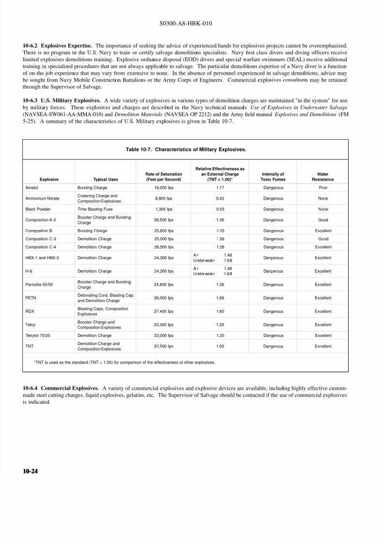