13470 psd 10 2012 30rby rqy 017 033 lr
DESCRIPTION
http://www.carrierpm.cz/uploads/13470_PSD_10_2012_30RBY_RQY_017_033_LR.pdfTRANSCRIPT
Quality Management
Systems
www.eurovent-certification.comwww.certiflash.com
Ductable Air-Cooled Liquid Chillers/Ductable Air-to-Water Heat Pumps
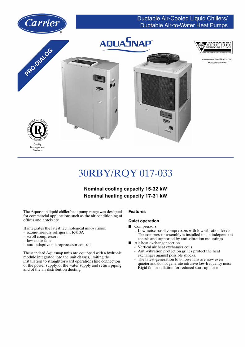
30RBY/RQY 017-033Nominal cooling capacity 15-32 kWNominal heating capacity 17-31 kW
The Aquasnap liquid chiller/heat pump range was designed for commercial applications such as the air conditioning of offices and hotels etc.
It integrates the latest technologi cal innovations: - ozone-friendly refrigerant R410A - scroll compressors - low-noise fans - auto-adaptive microprocessor control
The standard Aquasnap units are equipped with a hydronic module integrated into the unit chassis, limiting the installation to straightforward operations like connection of the power supply, of the water supply and return piping and of the air distribution ducting.
Features
Quiet operation ■ Compressors
- Low-noise scroll compressors with low vibration levels - The compressor assembly is installed on an independent
chassis and supported by anti-vibration mountings ■ Air heat exchanger section
- Vertical air heat exchanger coils - Anti-vibration protection grilles protect the heat
exchanger against possible shocks. - The latest-generation low-noise fans are now even
quieter and do not generate intrusive low-frequency noise - Rigid fan installation for reduced start-up noise

2
Easy and fast installation ■ Integrated hydronic module
- High-pressure centrifugal water pump - Water filter protecting the water pump against
circulating debris - High-capacity membrane expansion tank ensures
pressurisation of the water circuit - Overpressure valve, set to 4 bar - Pressure gauge to measure the system pressure. - Automatic purge valve positioned at the highest point of
the hydronic module to remove air from the system. - Thermal insulation and frost protection down to -10°C,
using an electric resistance heater and pump cycling. - Integrated water fill system to ensure correct water
pressure (option/accessory) ■ Physical features
- With its small footprint the unit blends in with any architectural styles.
- The unit is enclosed by easily removable panels, covering all components (except air heat exchanger and fans).
Access panels, sizes 017-021
■ Simplified electrical connections - A single power supply point - Main disconnect switch with high trip capacity - Transformer for safe 24 V control circuit supply included
■ Fast commissioning - Systematic factory operation test before shipment - Quick-test function for step-by-step verification of the
instruments, electrical components and motors
Economical operation ■ Increased energy efficiency at part load
- Eurovent energy efficiency class A and B in cooling mode and C in heating mode (in accordance with EN14511-3:2011).The exceptionally high energy efficiency of the Aquasnap unit is the result of a long qualification and optimisation process.
■ Reduced maintenance costs - Maintenance-free scroll compressors - Fast diagnosis of possible incidents and their history via
the Pro-Dialog+ control - R410A refrigerant is easier to use than other refrigerant
blends
Environmental care ■ Ozone-friendly R410A refrigerant
- Chlorine-free refrigerant of the HFC group with zero ozone depletion potential
- Very efficient - gives an increased energy efficiency ratio (EER)
■ Leak-tight refrigerant circuit - Brazed refrigerant connections for increased leak-
tightness - Verification of pressure transducers and temperature
sensors without transferring refrigerant charge
■ Easy duct connection - Rectangular discharge air connection. - Fan with 80 Pa available pressure. Centrifugal fan for
sizes 017 and 021, and axial fan for sizes 026 and 033. - Rectangular suction and filter connection option (sizes
017 and 021 only).
Inlet filters, sizes 017-021
3
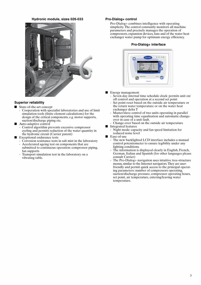
Pro-Dialog+ controlPro-Dialog+ combines intelligence with operating simplicity. The control constantly monitors all machine parameters and precisely manages the operation of compressors, expansion devices, fans and of the water heat exchanger water pump for optimum energy efficiency.
Pro-Dialog+ interface
\\MAINMENU\STATUS
Circuit B Total Capacity
CAPB_T 0 %DEM_LIM 100 %SP 4.2 °CCTRL_PNT -28.9 °CEMSTOP dsable
ENTERSTART/STOP
PRO-DIALOG+
■ Energy management - Seven-day internal time schedule clock: permits unit on/
off control and operation at a second set point - Set point reset based on the outside air temperature or
the return water temperature or on the water heat exchanger delta T
- Master/slave control of two units operating in parallel with operating time equalisation and automatic change-over in case of a unit fault.
- Change-over based on the outside air temperature ■ Integrated features
- Night mode: capacity and fan speed limitation for reduced noise level
■ Ease-of-use - The new backlighted LCD interface includes a manual
control potentiometer to ensure legibility under any lighting conditions.
- The information is displayed clearly in English, French, German, Italian and Spanish (for other languages please consult Carrier)
- The Pro-Dialog+ navigation uses intuitive tree-structure menus, similar to the Internet navigators. They are user-friendly and permit quick access to the principal operat-ing parameters: number of compressors operating, suction/discharge pressure, compressor operating hours, set point, air temperature, entering/leaving water temperature.
Hydronic module, sizes 026-033
Superior reliability ■ State-of-the-art concept
- Cooperation with specialist laboratories and use of limit simulation tools (finite element calculations) for the design of the critical components, e.g. motor supports, suction/discharge piping etc.
■ Auto-adaptive control - Control algorithm prevents excessive compressor
cycling and permits reduction of the water quantity in the hydronic circuit (Carrier patent)
■ Exceptional endurance tests - Corrosion resistance tests in salt mist in the laboratory - Accelerated ageing test on components that are
submitted to continuous operation: compressor piping, fan supports
- Transport simulation test in the laboratory on a vibrating table.
4
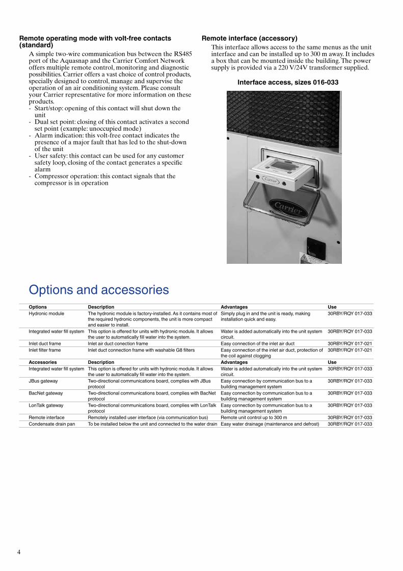
Remote interface (accessory)This interface allows access to the same menus as the unit interface and can be installed up to 300 m away. It includes a box that can be mounted inside the building. The power supply is provided via a 220 V/24V transformer supplied.
Interface access, sizes 016-033
Options and accessoriesOptions Description Advantages UseHydronic module The hydronic module is factory-installed. As it contains most of
the required hydronic components, the unit is more compact and easier to install.
Simply plug in and the unit is ready, making installation quick and easy.
30RBY/RQY 017-033
Integrated water fill system This option is offered for units with hydronic module. It allows the user to automatically fill water into the system.
Water is added automatically into the unit system circuit.
30RBY/RQY 017-033
Inlet duct frame Inlet air duct conection frame Easy connection of the inlet air duct 30RBY/RQY 017-021Inlet filter frame Inlet duct connection frame with washable G8 filters Easy connection of the inlet air duct, protection of
the coil against clogging30RBY/RQY 017-021
Accessories Description Advantages UseIntegrated water fill system This option is offered for units with hydronic module. It allows
the user to automatically fill water into the system.Water is added automatically into the unit system circuit.
30RBY/RQY 017-033
JBus gateway Two-directional communications board, complies with JBus protocol
Easy connection by communication bus to a building management system
30RBY/RQY 017-033
BacNet gateway Two-directional communications board, complies with BacNet protocol
Easy connection by communication bus to a building management system
30RBY/RQY 017-033
LonTalk gateway Two-directional communications board, complies with LonTalk protocol
Easy connection by communication bus to a building management system
30RBY/RQY 017-033
Remote interface Remotely installed user interface (via communication bus) Remote unit control up to 300 m 30RBY/RQY 017-033Condensate drain pan To be installed below the unit and connected to the water drain Easy water drainage (maintenance and defrost) 30RBY/RQY 017-033
Remote operating mode with volt-free contacts (standard)
A simple two-wire communication bus between the RS485 port of the Aquasnap and the Carrier Comfort Network offers multiple remote control, monitoring and diagnostic possibilities. Carrier offers a vast choice of control products, specially designed to control, manage and supervise the operation of an air conditioning system. Please consult your Carrier representative for more information on these products. - Start/stop: opening of this contact will shut down the
unit - Dual set point: closing of this contact activates a second
set point (example: unoccupied mode) - Alarm indication: this volt-free contact indicates the
presence of a major fault that has led to the shut-down of the unit
- User safety: this contact can be used for any customer safety loop, closing of the contact generates a specific alarm
- Compressor operation: this contact signals that the compressor is in operation

5
Hydronic module
Typical hydronic circuit diagram
The hydronic module reduces the installation time. The unit is factory-equipped with the main hydronic components required for the installation: screen filter, water pump, expansion tank, safety valve and pressure gauge.
The water heat exchanger and the hydronic module are protected against frost down to -10°C, using an electric resistance heater (standard) and pump cycling.
Physical and electrical dataThese are the same as for the standard unit except:30RBY/RQY - units with hydronic module 017 021 026 033Hydronic module Expansion tank volume l 5 5 8 8Maximum water-side operating pressure kPa 400 400 400 400PumpsWater pump Pump, screen filter, expansion tank, flow switch, pressure gauge, automatic purge valve, safety valvePower input* kW 0.54 0.59 0.99 1.10Nominal operating current draw* A 1.30 1.40 2.40 2.60
* Nominal conditions: evaporator entering/leaving water temperature 12°C/7°C, outside air temperature 35°C, evaporator fouling factor = 0 m2 K/kW. Gross performances, not in accordance with EN14511-3:2011. These performances do not take into account the correction for the proportional heating capacity and power input generated by the
water pump to overcome the internal pressure drop in the heat exchanger.
The hydronic module is integrated into the unit without increasing its dimensions and saves the space normally used for the water pump.
1
2
3 4
5
67
8
910
11
1213
1415
16
16
17
18
18
20
21
21
22
23
24
25
25
26 27
19
19
12
34
5
7
8
9
10
11
1213
1415
16
16
17
18
18
20
21
21
22
23
24
25
25
26 27
19
196
Sizes 17-21 kW Sizes 26-33 kW
Legend
Components of the unit and hydronic module1 Screen filter2 Expansion tank3 Safety valve4 High-pressure pump5 Air purge6 Water drain valve7 Flow sensor8 Plate heat exchanger leaving temperature sensor9 Plate heat exchanger entering temperature sensor10 Pressure gauge11 Plate heat exchanger12 Heat exchanger frost protection heater13 Pipe frost protection heater14 Shut-off valve (automatic water fill option)15 Pressure reducer (automatic water fill option)
Hydronic module (unit with hydronic module)
Automatic water fill system option
System components16 Temperature sensor well17 Air purge18 Flexible connections19 Shut-off valve20 Screen fiter (obligatory for a unit without hydronic module)21 Pressure gauge22 Flow control valve (factory-supplied for field installation)23 Charge valve24 Frost protection bypass (when shut-off valves are closed in winter)25 Pressure sensor26 System drain valves27 Plate heat exchanger drain valve

6
Physical data, 30RBY units30RBY 017 021 026 033Air conditioning application as per EN14511-3:2011*Condition 1Nominal cooling capacity kW 15.7 20.3 27.0 32.3EER kW/kW 2.65 2.60 2.88 3.05Eurovent class, cooling B B A AESEER kW/kW 2.93 2.86 3.15 3.32Condition 2Nominal cooling capacity kW 19.9 24.8 36.1 42.3EER kW/kW 3.07 2.85 3.49 3.67Air conditioning application**Condition 1Nominal cooling capacity kW 15.8 20.5 27.3 32.7EER kW/kW 2.74 2.71 3.03 3.20ESEER kW/kW 2.80 2.81 2.98 3.17Condition 2Nominal cooling capacity kW 20.1 25.1 36.7 42.9EER kW/kW 3.21 2.99 3.76 3.94Operating weight***Standard unit (with hydronic module) kg 209 228 255 280Standard unit (without hydronic module) kg 193 213 237 262Sound pressure level**** dB(A) 50 50 53 53Sound power level radiated from the unit† dB(A) 82 82 85 85Sound power level at unit discharge† dB(A) 80 80 91 91DimensionsLength x depth x height mm 1135 x 584 x 1608 1002 x 824 x 1829Compressor One scroll compressorRefrigerant charge R-410A kg 5.5 6.4 5.8 8.6Control Pro-Dialog+Fans Two 2-speed centrifugal fans, 5 backward-curved blades One 2-speed axial fan, 7 bladesDiameter mm 454 454 630 630Number of blades 5 5 7 7Available static pressure Pa 80 80 80 80Air flow l/s 1640 1640 3472 3472Speed r/s 20.5 20.5 21.5 21.5Air heat exchanger Copper tubes and aluminium fins, pipe diamter 3/8”, fin spacing 1.69 mmNumber of rows 2 2 2 3Number of pipes per row 60 60 60 60Water heat exchanger One plate heat exchangerWater volume l 1.52 1.90 2.28 2.85Maximum operating pressure kPa 1000 1000 1000 1000Standard unitWater connections (MPT gas) in 1 1 1-1/4 1-1/4Unit with hydronic module** Safety valve, screen filter, expansion tank, automatic air purge valve, water circuit drain valve, pressure gauge,
flow switchPump One single-speed pumpMaximum water-side operating pressure kPa 400 400 400 400Entering water connection in 1-1/4 1-1/4 1-1/4 1-1/4Leaving water connection in 1 1 1-1/4 1-1/4Expansion tank capacity l 5 5 8 8Water fill systemInlet/outlet diameter in 1/2 1/2 1/2 1/2Chassis paint colour Colour code: RAL 7035
* Eurovent-certified performances in accordance with standard EN14511-3:2011. Condition 1: Cooling mode conditions: evaporator water entering/leaving temperature 12°C/7°C, outside air temperature 35°C, evaporator fouling factor 0 m2 K/W Condition 2: Cooling mode conditions: evaporator water entering/leaving temperature 23°C/18°C, outside air temperature 35°C, evaporator fouling factor 0 m2 K/W ** Gross performances, not in accordance with EN14511-3:2011. These performances do not take into account the correction for the proportional heating capacity and power input generated by the
water pump to overcome the internal pressure drop in the heat exchanger. Condition 1: Cooling mode conditions: evaporator water entering/leaving temperature 12°C/7°C, outside air temperature 35°C, evaporator fouling factor 0 m2 K/W Condition 2: Cooling mode conditions: evaporator water entering/leaving temperature 23°C/18°C, outside air temperature 35°C, evaporator fouling factor 0 m2 K/W *** Weight shown is a guideline only. **** For information, calculated from the sound power level Lw(A) † In accordance with ISO 9614 (10-12 W)

7
Physical data, 30RQY units30RQY 017 021 026 033Air conditioning application as per EN14511-3:2011*Condition 1Nominal cooling capacity kW 14.9 19.0 27.1 32.3EER kW/kW 2.63 2.63 2.90 3.05Eurovent class, cooling B B A AESEER kW/kW 2.91 2.88 3.15 3.30Condition 2Nominal cooling capacity kW 18.4 23.9 35.6 41.3EER kW/kW 2.93 3.01 3.54 3.63Air conditioning application**Condition 1Nominal cooling capacity kW 15.0 19.2 27.3 32.6EER kW/kW 2.72 2.72 3.03 3.19ESEER kW/kW 2.78 2.78 2.97 3.16Condition 2Nominal cooling capacity kW 18.6 24.1 36.1 41.9EER kW/kW 3.06 3.15 3.77 3.87Heating application as per EN14511-3:2011*Condition 1Nominal heating capacity kW 17.0 20.5 28.8 31.4COP kW/kW 2.77 2.77 2.76 2.76Eurovent class, heating C C C CCondition 2Nominal heating capacity kW 17.5 20.8 29.9 32.3COP kW/kW 3.38 3.29 3.36 3.34Heating application**Condition 1Nominal heating capacity kW 16.9 20.3 28.5 31.1COP kW/kW 2.81 2.81 2.81 2.81Condition 2Nominal heating capacity kW 17.3 20.6 29.6 32.0COP kW/kW 3.45 3.36 3.44 3.42Operating weight***Standard unit (with hydronic module) kg 226 243 280 295Standard unit (without hydronic module) kg 211 228 262 277Sound pressure level**** dB(A) 50 50 53 53Sound power level radiated from the unit† dB(A) 82 82 85 85Sound power level at unit discharge† dB(A) 80 80 91 91DimensionsLength x depth x height mm 1135 x 584 x 1608 1002 x 824 x 1829Compressor One scroll compressorRefrigerant charge R-410A kg 6.4 7.7 7.6 9.5Control Pro-Dialog+Fans Two 2-speed centrifugal fans, 5 backward-curved blades One 2-speed axial fan, 7 bladesDiameter mm 454 454 630 630Available static pressure Pa 80 80 80 80Air flow l/s 1640 1640 3472 3472Speed r/s 20.5 20.5 21.5 21.5Air heat exchanger Copper tubes and aluminium fins, pipe diameter 3/8”, fin spacing 1.69 mmNumber of rows 2 2 2 3Number of pipes per row 60 60 60 60Water heat exchanger One plate heat exchangerWater volume l 1.52 1.90 2.28 2.85Maximum operating pressure kPa 1000 1000 1000 1000Standard unitWater connections (MPT gas) in 1 1 1-1/4 1-1/4Unit with hydronic module** Safety valve, screen filter, expansion tank, automatic air purge valve, water circuit drain valve, pressure gauge, flow switchPump One single-speed pumpMaximum water-side operating pressure kPa 400 400 400 400Entering (leaving) water connection in 1-1/4 (1) 1-1/4 (1) 1-1/4 (1-1/4) 1-1/4 (1-1/4)Expansion tank capacity l 5 5 8 8Water fill systemInlet/outlet diameter in 1/2 1/2 1/2 1/2Chassis paint colour Colour code: RAL 7035
* Eurovent-certified performances in accordance with standard EN14511-3:2011. Condition 1: Cooling mode conditions: evaporator water entering/leaving temperature 12°C/7°C, outside air temperature 35°C, evaporator fouling factor 0 m2 K/W Condition 2: Cooling mode conditions: evaporator water entering/leaving temperature 23°C/18°C, outside air temperature 35°C, evaporator fouling factor 0 m2 K/W Condition 1: Heating mode conditions: water heat exchanger water entering/leaving temperature 40°C/45°C, outside air temperature 7°C db/6°C wb, evaporator fouling factor 0 m2 K/W.
Condition 2: Heating mode conditions: water heat exchanger water entering/leaving temperature 30°C/35°C, outside air temperature 7°C db/6°C wb, evaporator fouling factor 0 m2 K/W. ** Gross performances, not in accordance with EN14511-3:2011. These performances do not take into account the correction for the proportional heating capacity and power input generated by the
water pump to overcome the internal pressure drop in the heat exchanger. Condition 1: Cooling mode conditions: evaporator water entering/leaving temperature 12°C/7°C, outside air temperature 35°C, evaporator fouling factor 0 m2 K/W Condition 2: Cooling mode conditions: evaporator water entering/leaving temperature 23°C/18°C, outside air temperature 35°C, evaporator fouling factor 0 m2 K/W Condition 1: Heating mode conditions: water heat exchanger water entering/leaving temperature 40°C/45°C, outside air temperature 7°C db/6°C wb, evaporator fouling factor 0 m2 K/W.
Condition 2: Heating mode conditions: water heat exchanger water entering/leaving temperature 30°C/35°C, outside air temperature 7°C db/6°C wb, evaporator fouling factor 0 m2 K/W. *** Weight shown is a guideline only. **** For information, calculated from the sound power level Lw(A) † In accordance with ISO 9614 (10-12 W)

8
Electrical data, 30RBY/RQY units30RBY/RQY 017 021 026 033Power circuitNominal power supply V-ph-Hz 400-3-50Voltage range V 340-440Control circuit supply 24 V via internal transformerMaximum start-up current (Un)* A 75 95 118 118Unit power factor at nominal capacity** 0.84 0.79 0.77 0.81Maximum operating power input** kW 8.0 9.3 11.2 14.0Nominal unit operating current draw*** A 8 12 20 21Maximum operating current draw (Un)**** A 13 16 20 24Maximum operating current draw (Un-15%)† A 15 18 23 27
* Maximum instantaneous start-up current (locked rotor current of the compressor). ** Power input, compressors and fans, at the unit operating limits (saturated suction temperature 10°C, saturated condensing temperature 65°C) and nominal voltage of 400 V (data given on the unit
nameplate). *** Standardised Eurovent conditions: water heat exchanger entering/leaving water temperature 12°C/7°C, outside air temperature 35°C. **** Maximum unit operating current at maximum unit power input and 400 V (values given on the unit nameplate). † Maximum unit operating current at maximum unit power input and 340-460 V.
Part load performancesWith the rapid increase in energy costs and the care about environmental impacts of electricity production, the power consumption of air conditioning equipment has become an important topic. The energy efficiency of a unit at full load is rarely representative of the actual performance of the units, as on average a unit works less than 5% of the time at full load.
IPLV (in accordance with AHRI 550/590)The IPLV (integrated part load value) allows evaluation of the average energy efficiency based on four operating conditions defined by the AHRI (Air Conditioning, Heating and Refrigeration Institute). The IPLV is the average weighted value of the energy efficiency ratios (EER) at different operating conditions, weighted by the operating time.
IPLV (integrated part load value)Load % Air temperature °C Energy efficiency Operating time %100 35 EER1 175 26.7 EER2 4250 18.3 EER3 4525 12.8 EER4 12ESEER = EER1 x 1% + EER2 x 42% + EER3 x 45% + EER4 x 12%
The heat load of a building depends on many factors, such as the outside air temperature, the exposure to the sun and the building occupancy.
Consequently it is preferable to use the average energy efficiency, calculated at several operating points that are representative for the unit utilisation.
ESEER (in accordance with EUROVENT)The ESEER (European seasonal energy efficiency ratio) permits evaluation of the average energy efficiency at part load, based on four operating conditions defined by Eurovent. The ESEER is the average value of energy efficiency ratios (EER) at different operating conditions, weighted by the operating time.
ESEER (European seasonal energy efficiency ratio)Load % Air temperature °C Energy efficiency Operating time %100 35 EER1 375 30 EER2 3350 25 EER3 4125 20 EER4 23ESEER = EER1 x 3% + EER2 x 33% + EER3 x 41% + EER4 x 23%
Part load performances
30RBY 017-03330RBY 017 021 026 033IPLV kW/kW 3.34 3.30 3.49 3.69ESEER kW/kW 2.93 2.86 3.15 3.32
30RQY 017-03330RQY 017 021 026 033IPLV kW/kW 3.29 3.29 3.48 3.68ESEER kW/kW 2.91 2.88 3.15 3.30
ESEER Calculations according to standard performances (in accordance with EN14511-3:2011) and certified by Eurovent.
IPLV Calculations according to standard performances (in accordance with AHRI 550-590)

9
-12
-7
-2
3
8
13
18
23
28
33
38
43
48
53
-4 -2 0 2 4 6 8 10 12 14 16 18 20 22 24
Operating limitsWater heat exchanger water flow rate
30RBY Flow rate, l/sMinimum Maximum* Maximum**
017 0.45 1.39 1.26021 0.57 1.52 1.42026 0.67 1.96 1.43033 0.87 2.18 1.72
30RQY Flow rate, l/sMinimum Maximum* Maximum**
017 0.45 1.39 1.26021 0.57 1.52 1.42026 0.67 2.18 1.72033 0.87 2.29 1.85
* Maximum flow rate at an available pressure of 50 kPa (unit with hydronic module) ** Maximum flow rate at pressure drop of 100 kPa in the plate heat exchanger (unit without
hydronic module).
Evaporator leaving water temperature, °C
Out
side
air
tem
pera
ture
, °C
Operating range with anti-freeze solution and Pro-Dialog configuration.
30RBY/RQY (cooling mode) 30RQY (heating mode)
-20
-10
0
10
20
30
40
15 20 25 30 35 40 45 50 55
Water heat exchanger leaving water temperature, °C
Out
side
air
tem
pera
ture
, °C
Sound spectrum, 30RBY/RQY units30RBY/RQY Octave bands, Hz Sound power levels
125 250 500 1000 2000 4000 8000017 Radiated dB 95 80 78 73 71 69 65 dB(A) 82021 dB 95 80 78 73 71 69 65 dB(A) 82026 dB 95 84 80 79 78 72 68 dB(A) 85033 dB 95 84 80 79 78 72 68 dB(A) 85017 Fan outlet dB 88 79 77 74 71 68 65 dB(A) 80021 dB 88 79 77 74 71 68 65 dB(A) 80026 dB 91 85 84 87 86 78 71 dB(A) 91033 dB 91 85 84 87 86 78 71 dB(A) 91

10
Available static system pressure30RBY 017-033
Avai
labl
e st
atic
pre
ssur
e, k
Pa
Water flow rate, l/sLegend1. 30RBY 0172. 30RBY 0213. 30RBY 0264. 30RBY 033
1 112 4
60
80
100
120
140
160
180
200
220
240
260
280
300
0,0 0,5 1,0 1,5 2,0 2,5
3
60
80
100
120
140
160
180
200
220
240
260
280
300
0,0 0,5 1,0 1,5 2,0 2,5
1 112 3 4
30RQY 017-033
Legend1. 30RQY 0172. 30RQY 0213. 30RQY 0264. 30RQY 033
Avai
labl
e st
atic
pre
ssur
e, k
Pa
Water flow rate, l/s
11
Cooling modeAir duct conditions, 30RBY/RQY 017-021Duct pressure drop, Pa Air flow factor Cooling capacity factor EER factor Power input factor0 1.129 1.053 1.087 0.96220 1.097 1.047 1.076 0.96640 1.064 1.034 1.050 0.97960 1.032 1.021 1.022 0.99080 1.000 1.000 1.000 1.000
Air duct conditions, 30RBY/RQY 026-033Duct pressure drop, Pa Air flow factor Cooling capacity factor EER factor Power input factor0 1.200 1.042 1.075 0.97120 1.150 1.033 1.065 0.97440 1.100 1.021 1.043 0.98160 1.049 1.010 1.022 0.99080 1.000 1.000 1.000 1.000
Heating modeAir duct conditions, 30RQY 017-021Duct pressure drop, Pa Air flow factor Heating capacity factor COP factor Power input factor0 1.129 1.020 1.020 1.00020 1.097 1.018 1.018 1.00040 1.064 1.015 1.015 1.00060 1.032 1.008 1.008 1.00080 1.000 1.000 1.000 1.000
Air duct conditions, 30RQY 026-033Duct pressure drop, Pa Air flow factor Heating capacity factor COP factor Power input factor0 1.200 1.015 1.015 1.00020 1.150 1.012 1.012 1.00040 1.100 1.009 1.009 1.00060 1.049 1.005 1.005 1.00080 1.000 1.000 1.000 1.000
Filter option30RBY/RQY 017 021Filter pressure dropClean filter Pa 10 10Clogged filter Pa 20 20
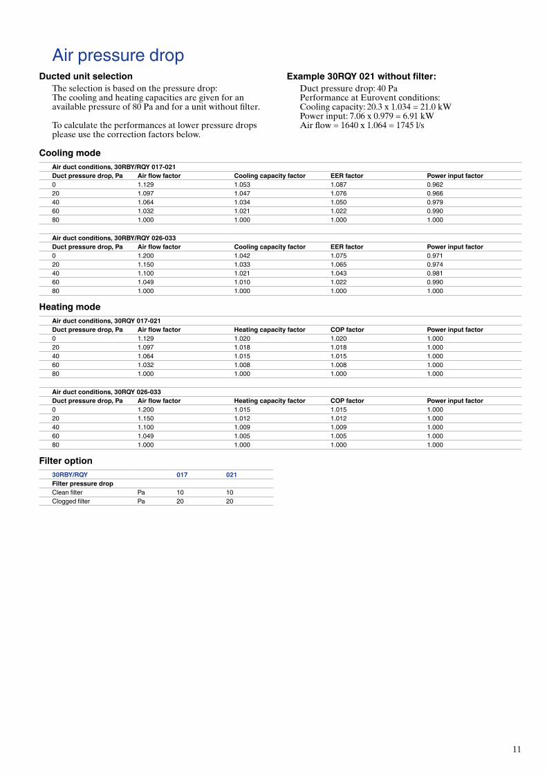
Air pressure dropDucted unit selection
The selection is based on the pressure drop:The cooling and heating capacities are given for an available pressure of 80 Pa and for a unit without filter.
To calculate the performances at lower pressure drops please use the correction factors below.
Example 30RQY 021 without filter:Duct pressure drop: 40 PaPerformance at Eurovent conditions:Cooling capacity: 20.3 x 1.034 = 21.0 kWPower input: 7.06 x 0.979 = 6.91 kWAir flow = 1640 x 1.064 = 1745 l/s
12
1005028
60065
170579
5
155
120
5
21
43
150100
82
1135
1570
1608
584
559
162 660 281
522
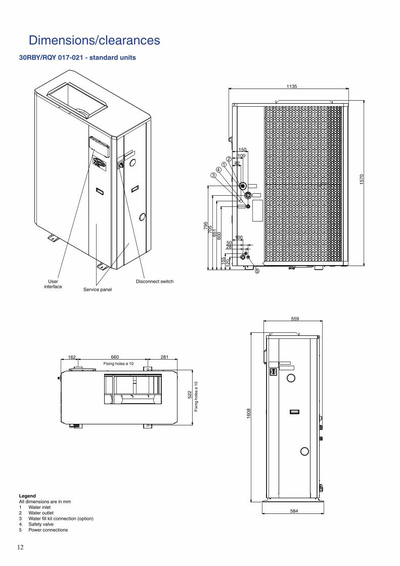
Dimensions/clearances30RBY/RQY 017-021 - standard units
User interface Service panel
Disconnect switch
Fixing holes ø 10
Fixi
ng h
oles
ø 1
0
LegendAll dimensions are in mm1 Water inlet2 Water outlet3 Water fill kit connection (option)4. Safety valve5 Power connections
13
5
21
43
1005028
60065
170579
5
155
120
15010082
1135
1570
1608
584
559
522
162 660 281
594
580
1476
50
357
50 729
1185
1185
1476
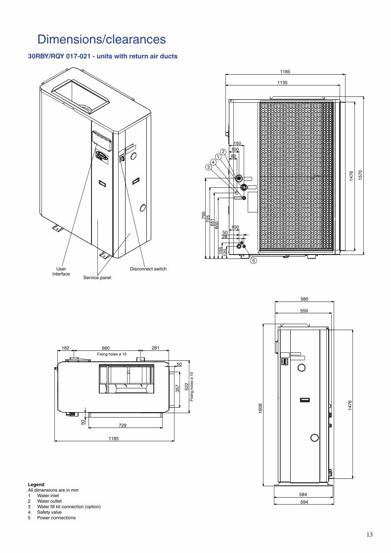
Dimensions/clearances30RBY/RQY 017-021 - units with return air ducts
User interface
Service panel
Disconnect switch
Fixing holes ø 10
Fixi
ng h
oles
ø 1
0
LegendAll dimensions are in mm1 Water inlet2 Water outlet3 Water fill kit connection (option)4. Safety valve5 Power connections

14
Dimensions/clearances30RBY/RQY 017-021 - units with filter frame on the return air side
1291
1135
1570
1476
5
21
43
15010082
1005028
795
705
651
600
155
120
686
559
1608 14
76
700
584
660162 281
729
1291
156
156
357 52
2
User interface Service panel
Disconnect switch
Fixing holes ø 10
Fixi
ng h
oles
ø 1
0
LegendAll dimensions are in mm1 Water inlet2 Water outlet3 Water fill kit connection (option)4. Safety valve5 Power connections

15
2170170 460
41
3
180
50
264148
3511
5
995724
153
367
7451002
760712
50
1829
1640
710824
Dimensions/clearances30RBY/RQY 026-033
LegendAll dimensions are in mm1 Water inlet2 Water outlet3 Water fill kit connection (option)4 Power connections
Fixing holes ø 10Fixing holes ø 10
User interface
Service panel
Disconnect switch
16
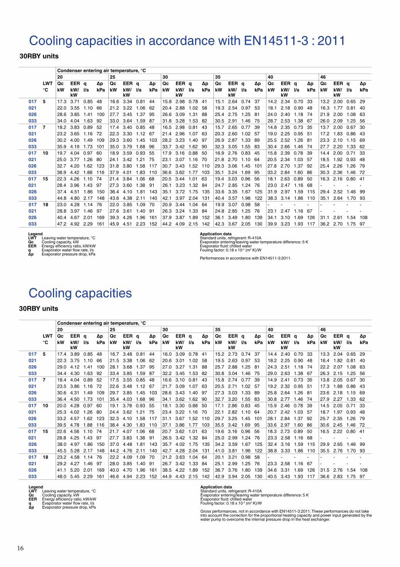
Cooling capacities in accordance with EN14511-3 : 201130RBY units
Condenser entering air temperature, °C20 25 30 35 40 46
LWT Qc EER q Δp Qc EER q Δp Qc EER q Δp Qc EER q Δp Qc EER q Δp Qc EER q Δp°C kW kW/
kWl/s kPa kW kW/
kWl/s kPa kW kW/
kWl/s kPa kW kW/
kWl/s kPa kW kW/
kWl/s kPa kW kW/
kWl/s kPa
017 5 17.3 3.71 0.85 48 16.6 3.34 0.81 44 15.8 2.98 0.78 41 15.1 2.64 0.74 37 14.2 2.34 0.70 33 13.2 2.00 0.65 29021 22.0 3.55 1.10 66 21.2 3.22 1.06 62 20.4 2.88 1.02 58 19.3 2.54 0.97 53 18.1 2.18 0.90 48 16.3 1.77 0.81 40026 28.6 3.85 1.41 100 27.7 3.45 1.37 95 26.6 3.09 1.31 88 25.4 2.75 1.25 81 24.0 2.40 1.18 74 21.9 2.00 1.08 63033 34.0 4.04 1.63 92 33.0 3.64 1.59 87 31.8 3.28 1.53 82 30.5 2.91 1.46 75 28.7 2.53 1.38 67 26.0 2.09 1.25 56017 7 18.2 3.83 0.89 52 17.4 3.40 0.85 48 16.5 2.98 0.81 43 15.7 2.65 0.77 39 14.8 2.35 0.73 35 13.7 2.00 0.67 30021 23.2 3.65 1.16 72 22.3 3.30 1.12 67 21.4 2.96 1.07 63 20.3 2.60 1.02 57 19.0 2.25 0.95 51 17.2 1.83 0.86 43026 30.2 4.00 1.49 109 29.3 3.60 1.45 103 28.2 3.23 1.40 97 26.9 2.87 1.33 89 25.5 2.52 1.26 81 23.3 2.10 1.15 69033 35.9 4.19 1.73 101 35.0 3.79 1.68 96 33.7 3.42 1.62 90 32.3 3.05 1.55 83 30.4 2.66 1.46 74 27.7 2.20 1.33 62017 10 19.7 4.04 0.97 60 18.9 3.59 0.93 55 17.9 3.16 0.88 50 16.9 2.76 0.83 45 15.8 2.39 0.78 39 14.4 2.00 0.71 33021 25.0 3.77 1.26 80 24.1 3.42 1.21 75 23.1 3.07 1.16 70 21.8 2.70 1.10 64 20.5 2.34 1.03 57 18.5 1.92 0.93 48026 32.7 4.20 1.62 123 31.8 3.80 1.58 117 30.7 3.43 1.52 110 29.3 3.06 1.45 101 27.8 2.70 1.37 92 25.4 2.26 1.26 79033 38.9 4.42 1.88 116 37.9 4.01 1.83 110 36.6 3.62 1.77 103 35.1 3.24 1.69 95 33.2 2.84 1.60 86 30.3 2.36 1.46 72017 15 22.3 4.26 1.10 74 21.4 3.84 1.06 68 20.5 3.44 1.01 63 19.4 3.03 0.96 56 18.1 2.63 0.89 50 16.3 2.16 0.80 41021 28.4 3.96 1.43 97 27.3 3.60 1.38 91 26.1 3.23 1.32 84 24.7 2.85 1.24 76 23.0 2.47 1.16 68 - - - -026 37.4 4.51 1.86 150 36.4 4.10 1.81 143 35.1 3.72 1.75 135 33.6 3.35 1.67 125 31.9 2.97 1.59 115 29.4 2.52 1.46 99033 44.8 4.80 2.17 148 43.6 4.38 2.11 140 42.1 3.97 2.04 131 40.4 3.57 1.96 122 38.3 3.14 1.86 110 35.1 2.64 1.70 93017 18 23.0 4.28 1.14 76 22.0 3.85 1.09 70 20.9 3.44 1.04 64 19.9 3.07 0.98 58 - - - - - - - -021 28.8 3.97 1.46 97 27.6 3.61 1.40 91 26.3 3.24 1.33 84 24.8 2.85 1.25 76 23.1 2.47 1.16 67 - - - -026 40.4 4.67 2.01 169 39.3 4.26 1.96 161 37.9 3.87 1.89 152 36.1 3.49 1.80 139 34.1 3.10 1.69 126 31.1 2.61 1.54 108033 47.2 4.92 2.29 161 45.9 4.51 2.23 152 44.2 4.09 2.15 142 42.3 3.67 2.05 130 39.9 3.23 1.93 117 36.2 2.70 1.75 97
Cooling capacities30RBY units
Condenser entering air temperature, °C20 25 30 35 40 46
LWT Qc EER q Δp Qc EER q Δp Qc EER q Δp Qc EER q Δp Qc EER q Δp Qc EER q Δp°C kW kW/
kWl/s kPa kW kW/
kWl/s kPa kW kW/
kWl/s kPa kW kW/
kWl/s kPa kW kW/
kWl/s kPa kW kW/
kWl/s kPa
017 5 17.4 3.89 0.85 48 16.7 3.48 0.81 44 16.0 3.09 0.78 41 15.2 2.73 0.74 37 14.4 2.40 0.70 33 13.3 2.04 0.65 29021 22.3 3.75 1.10 66 21.5 3.38 1.06 62 20.6 3.01 1.02 58 19.5 2.63 0.97 53 18.2 2.25 0.90 48 16.4 1.82 0.81 40026 29.0 4.12 1.41 100 28.1 3.68 1.37 95 27.0 3.27 1.31 88 25.7 2.88 1.25 81 24.3 2.51 1.18 74 22.2 2.07 1.08 63033 34.4 4.30 1.63 92 33.4 3.85 1.59 87 32.2 3.45 1.53 82 30.8 3.04 1.46 75 29.0 2.63 1.38 67 26.3 2.15 1.25 56017 7 18.4 4.04 0.89 52 17.5 3.55 0.85 48 16.6 3.10 0.81 43 15.8 2.74 0.77 39 14.9 2.41 0.73 35 13.8 2.05 0.67 30021 23.5 3.86 1.16 72 22.6 3.48 1.12 67 21.7 3.09 1.07 63 20.5 2.71 1.02 57 19.2 2.32 0.95 51 17.3 1.88 0.86 43026 30.6 4.31 1.49 109 29.7 3.85 1.45 103 28.6 3.43 1.40 97 27.3 3.03 1.33 89 25.8 2.64 1.26 81 23.6 2.18 1.15 69033 36.4 4.50 1.73 101 35.4 4.03 1.68 96 34.1 3.62 1.62 90 32.7 3.20 1.55 83 30.8 2.77 1.46 74 27.9 2.27 1.33 62017 10 20.0 4.28 0.97 60 19.1 3.78 0.93 55 18.1 3.30 0.88 50 17.1 2.86 0.83 45 15.9 2.46 0.78 39 14.5 2.05 0.71 33021 25.3 4.02 1.26 80 24.4 3.62 1.21 75 23.4 3.22 1.16 70 22.1 2.82 1.10 64 20.7 2.42 1.03 57 18.7 1.97 0.93 48026 33.2 4.57 1.62 123 32.3 4.10 1.58 117 31.1 3.67 1.52 110 29.7 3.25 1.45 101 28.1 2.84 1.37 92 25.7 2.35 1.26 79033 39.5 4.78 1.88 116 38.4 4.30 1.83 110 37.1 3.86 1.77 103 35.5 3.42 1.69 95 33.6 2.97 1.60 86 30.6 2.45 1.46 72017 15 22.6 4.56 1.10 74 21.7 4.07 1.06 68 20.7 3.62 1.01 63 19.6 3.16 0.96 56 18.3 2.73 0.89 50 16.5 2.22 0.80 41021 28.8 4.25 1.43 97 27.7 3.83 1.38 91 26.5 3.42 1.32 84 25.0 2.99 1.24 76 23.3 2.58 1.16 68 - - - -026 38.0 4.97 1.86 150 37.0 4.48 1.81 143 35.7 4.02 1.75 135 34.2 3.59 1.67 125 32.4 3.16 1.59 115 29.9 2.65 1.46 99033 45.5 5.28 2.17 148 44.2 4.76 2.11 140 42.7 4.28 2.04 131 41.0 3.81 1.96 122 38.8 3.33 1.86 110 35.5 2.76 1.70 93017 18 23.2 4.58 1.14 76 22.2 4.09 1.09 70 21.2 3.63 1.04 64 20.1 3.21 0.98 58 - - - - - - - -021 29.2 4.27 1.46 97 28.0 3.85 1.40 91 26.7 3.42 1.33 84 25.1 2.99 1.25 76 23.3 2.58 1.16 67 - - - -026 41.1 5.20 2.01 169 40.0 4.70 1.96 161 38.5 4.22 1.89 152 36.7 3.76 1.80 139 34.6 3.31 1.69 126 31.5 2.76 1.54 108033 48.0 5.45 2.29 161 46.6 4.94 2.23 152 44.9 4.43 2.15 142 42.9 3.94 2.05 130 40.5 3.43 1.93 117 36.6 2.83 1.75 97
Application data Standard units, refrigerant: R-410A Evaporator entering/leaving water temperature difference: 5 K Evaporator fluid: chilled water Fouling factor: 0.18 x 10⁻⁴ (m2 K)/W Performances in accordance with EN14511-3:2011.
Legend LWT Leaving water temperature, °C Qc Cooling capacity, kW EER Energy efficiency ratio, kW/kW q Evaporator water flow rate, l/s Δp Evaporator pressure drop, kPa
Application data Standard units, refrigerant: R-410A Evaporator entering/leaving water temperature difference: 5 K Evaporator fluid: chilled water Fouling factor: 0.18 x 10⁻⁴ (m2 K)/W Gross performances, not in accordance with EN14511-3:2011. These performances do not take
into account the correction for the proportional heating capacity and power input generated by the water pump to overcome the internal pressure drop in the heat exchanger.
Legend LWT Leaving water temperature, °C Qc Cooling capacity, kW EER Energy efficiency ratio, kW/kW q Evaporator water flow rate, l/s Δp Evaporator pressure drop, kPa

17
Cooling capacities in accordance with EN14511-3 : 201130RQY units
Condenser entering air temperature, °C20 25 30 35 40 46
LWT Qc EER q Δp Qc EER q Δp Qc EER q Δp Qc EER q Δp Qc EER q Δp Qc EER q Δp°C kW kW/
kWl/s kPa kW kW/
kWl/s kPa kW kW/
kWl/s kPa kW kW/
kWl/s kPa kW kW/
kWl/s kPa kW kW/
kWl/s kPa
017 5 16.4 3.66 0.81 44 15.7 3.30 0.77 40 15.0 2.91 0.74 37 14.2 2.55 0.70 33 13.3 2.22 0.65 30 12.1 1.84 0.60 25021 20.5 3.54 0.98 55 19.8 3.17 0.95 51 18.9 2.85 0.91 48 18.0 2.53 0.86 44 16.9 2.19 0.81 40 15.3 1.79 0.73 33026 28.6 3.88 1.42 70 27.7 3.49 1.37 66 26.7 3.12 1.32 62 25.5 2.77 1.26 57 24.0 2.42 1.19 51 22.0 2.01 1.09 43033 34.1 4.1 1.7 82.2 33.1 3.65 1.62 78 31.9 3.29 1.56 72 30.5 2.92 1.48 66 28.6 2.53 1.39 58 25.8 2.08 1.26 48017 7 17.2 3.77 0.85 47 16.5 3.40 0.81 44 15.7 3.00 0.78 40 14.9 2.63 0.73 36 14.0 2.29 0.69 32 12.8 1.91 0.63 27021 21.6 3.67 1.04 59 20.9 3.29 1.00 56 20.0 2.96 0.96 52 19.0 2.63 0.91 48 17.8 2.28 0.85 43 16.1 1.87 0.77 36026 30.3 4.04 1.50 78 29.4 3.64 1.46 73 28.3 3.26 1.40 68 27.0 2.90 1.34 63 25.5 2.54 1.27 56 23.4 2.12 1.16 48033 36.1 4.21 1.76 90 35.0 3.80 1.71 86 33.7 3.43 1.65 79 32.3 3.05 1.58 73 30.3 2.66 1.48 65 27.4 2.19 1.34 53017 10 18.6 3.93 0.92 54 17.8 3.55 0.88 50 17.0 3.15 0.84 46 16.1 2.76 0.80 41 15.1 2.41 0.75 37 13.8 2.02 0.68 31021 23.4 3.86 1.13 66 22.6 3.47 1.09 63 21.7 3.13 1.04 58 20.7 2.8 1.0 54 19.4 2.43 0.93 48 17.5 1.99 0.84 41026 32.8 4.26 1.63 89 31.9 3.85 1.59 84 30.7 3.47 1.53 79 29.4 3.10 1.46 72 27.9 2.73 1.38 65 25.6 2.28 1.27 55033 39.2 4.44 1.92 105 38.1 4.02 1.87 99 36.7 3.64 1.80 92 35.1 3.25 1.72 84 33.1 2.84 1.62 75 30.1 2.36 1.47 62017 15 20.9 4.07 1.04 66 20.0 3.69 1.00 61 19.1 3.30 0.95 56 18.2 2.93 0.90 50 17.1 2.58 0.85 45 15.6 2.18 0.78 38021 26.6 3.99 1.28 80 25.7 3.64 1.24 76 24.7 3.32 1.19 71 23.6 3.00 1.14 66 22.3 2.68 1.07 60 20.2 2.21 0.97 50026 37.7 4.63 1.88 113 36.7 4.22 1.83 107 35.5 3.8 1.8 101 34.0 3.43 1.70 93 32.3 3.04 1.61 84 29.8 2.57 1.48 72033 45.0 4.82 2.21 133 43.7 4.39 2.15 126 42.1 3.97 2.07 117 40.3 3.57 1.98 108 38.1 3.14 1.87 97 34.7 2.63 1.70 80017 18 21.3 4.1 1.1 66.8 20.4 3.71 1.01 62 19.4 3.31 0.97 56 18.4 2.93 0.91 51 - - - - - - - -021 27.1 4.0 1.3 81.5 26.1 3.65 1.26 76 25.0 3.33 1.21 71 23.9 3.01 1.15 66 22.5 2.69 1.08 59 20.2 2.21 0.97 50026 39.9 4.8 2.0 123.7 38.7 4.35 1.94 117 37.3 3.94 1.87 109 35.6 3.54 1.78 100 33.7 3.13 1.68 90 30.8 2.63 1.53 76033 46.4 4.9 2.3 139.9 45.0 4.47 2.22 132 43.3 4.04 2.13 122 41.3 3.63 2.03 111 39.0 3.19 1.92 99 35.2 2.65 1.73 81
Cooling capacities30RQY units
Condenser entering air temperature, °C20 25 30 35 40 46
LWT Qc EER q Δp Qc EER q Δp Qc EER q Δp Qc EER q Δp Qc EER q Δp Qc EER q Δp°C kW kW/
kWl/s kPa kW kW/
kWl/s kPa kW kW/
kWl/s kPa kW kW/
kWl/s kPa kW kW/
kWl/s kPa kW kW/
kWl/s kPa
017 5 16.5 3.83 0.81 44 15.8 3.43 0.77 40 15.1 3.02 0.74 37 14.3 2.63 0.70 33 13.4 2.27 0.65 30 12.2 1.88 0.60 25021 20.7 3.71 0.98 55 20.0 3.31 0.95 51 19.1 2.96 0.91 48 18.2 2.61 0.86 44 17.0 2.25 0.81 40 15.4 1.83 0.73 33026 28.9 4.11 1.42 70 28.0 3.66 1.37 66 27.0 3.26 1.32 62 25.7 2.88 1.26 57 24.3 2.50 1.19 51 22.2 2.06 1.09 43033 34.5 4.3 1.7 82.2 33.5 3.85 1.62 78 32.2 3.45 1.56 72 30.8 3.04 1.48 66 28.9 2.62 1.39 58 26.1 2.14 1.26 48017 7 17.4 3.96 0.85 47 16.7 3.55 0.81 44 15.9 3.12 0.78 40 15.0 2.72 0.73 36 14.1 2.36 0.69 32 12.9 1.96 0.63 27021 21.8 3.85 1.04 59 21.1 3.44 1.00 56 20.2 3.08 0.96 52 19.2 2.72 0.91 48 18.0 2.35 0.85 43 16.3 1.91 0.77 36026 30.6 4.29 1.50 78 29.7 3.84 1.46 73 28.6 3.42 1.40 68 27.3 3.02 1.34 63 25.8 2.64 1.27 56 23.6 2.18 1.16 48033 36.5 4.49 1.76 90 35.5 4.03 1.71 86 34.1 3.61 1.65 79 32.6 3.19 1.58 73 30.6 2.76 1.48 65 27.7 2.26 1.34 53017 10 18.8 4.15 0.92 54 18.0 3.72 0.88 50 17.2 3.28 0.84 46 16.2 2.86 0.80 41 15.2 2.48 0.75 37 13.9 2.07 0.68 31021 23.7 4.08 1.13 66 22.9 3.64 1.09 63 21.9 3.27 1.04 58 20.9 2.9 1.0 54 19.6 2.51 0.93 48 17.7 2.05 0.84 41026 33.2 4.56 1.63 89 32.3 4.09 1.59 84 31.1 3.66 1.53 79 29.8 3.24 1.46 72 28.2 2.84 1.38 65 25.8 2.35 1.27 55033 39.7 4.78 1.92 105 38.6 4.30 1.87 99 37.1 3.85 1.80 92 35.5 3.41 1.72 84 33.5 2.96 1.62 75 30.4 2.44 1.47 62017 15 21.1 4.32 1.04 66 20.3 3.90 1.00 61 19.3 3.46 0.95 56 18.3 3.05 0.90 50 17.3 2.67 0.85 45 15.8 2.24 0.78 38021 26.9 4.25 1.28 80 26.0 3.85 1.24 76 25.0 3.50 1.19 71 23.9 3.14 1.14 66 22.5 2.79 1.07 60 20.4 2.28 0.97 50026 38.2 5.03 1.88 113 37.2 4.54 1.83 107 36.0 4.1 1.8 101 34.5 3.64 1.70 93 32.7 3.20 1.61 84 30.1 2.67 1.48 72033 45.6 5.27 2.21 133 44.3 4.75 2.15 126 42.7 4.27 2.07 117 40.8 3.80 1.98 108 38.6 3.31 1.87 97 35.1 2.74 1.70 80017 18 21.5 4.3 1.1 66.8 20.6 3.92 1.01 62 19.7 3.47 0.97 56 18.6 3.06 0.91 51 - - - - - - - -021 27.4 4.3 1.3 81.5 26.4 3.86 1.26 76 25.3 3.50 1.21 71 24.1 3.15 1.15 66 22.7 2.80 1.08 59 20.4 2.28 0.97 50026 40.4 5.2 2.0 123.7 39.3 4.71 1.94 117 37.9 4.23 1.87 109 36.1 3.77 1.78 100 34.1 3.30 1.68 90 31.1 2.75 1.53 76033 47.1 5.4 2.3 139.9 45.7 4.85 2.22 132 43.9 4.35 2.13 122 41.9 3.87 2.03 111 39.4 3.36 1.92 99 35.6 2.77 1.73 81
Application data
Standard units, refrigerant: R-410A Evaporator entering/leaving water temperature difference: 5 K Evaporator fluid: chilled water Fouling factor: 0.18 x 10⁻⁴ (m2 K)/W Performances in accordance with EN14511-3:2011.
Legend LWT Leaving water temperature, °C Qc Cooling capacity, kW EER Energy efficiency ratio, kW/kW q Evaporator water flow rate, l/s Δp Evaporator pressure drop, kPa
Application data Standard units, refrigerant: R-410A Evaporator entering/leaving water temperature difference: 5 K Evaporator fluid: chilled water Fouling factor: 0.18 x 10⁻⁴ (m2 K)/W Gross performances, not in accordance with EN14511-3:2011. These performances do not take
into account the correction for the proportional heating capacity and power input generated by the water pump to overcome the internal pressure drop in the heat exchanger.
Legend LWT Leaving water temperature, °C Qc Cooling capacity, kW EER Energy efficiency ratio, kW/kW q Evaporator water flow rate, l/s Δp Evaporator pressure drop, kPa

18
Heating capacities in accordance with EN14511-3 : 201130RQY units
Outside air dry-bulb (wet-bulb) temperature. °C-15 (-16) -10 (-11) -7 (-8) 2 (1) 7 (6) 12 (11)
LWT Qh COP q Δp Qh COP q Δp Qh COP q Δp Qh COP q Δp Qh COP q Δp Qh COP q Δp°C kW kW/
kWl/s kPa kW kW/
kWl/s kPa kW kW/
kWl/s kPa kW kW/
kWl/s kPa kW kW/
kWl/s kPa kW kW/
kWl/s kPa
017 30 8.8 1.78 0.47 14 9.6 1.93 0.54 18 10.1 2.04 0.58 21 12.8 2.72 0.74 33 17.7 3.67 0.84 41 20.2 4.08 0.96 53021 10.8 1.79 0.58 20 11.6 1.92 0.65 24 12.2 2.02 0.70 27 15.2 2.61 0.88 40 21.0 3.54 1.00 49 23.9 3.91 1.13 60026 14.8 1.73 0.79 22 16.3 1.90 0.91 28 17.2 2.01 0.99 33 21.8 2.69 1.26 53 30.2 3.64 1.44 67 34.5 4.08 1.64 86033 - - - - 17.7 1.92 0.99 28 18.7 2.02 1.07 33 23.6 2.68 1.36 52 32.5 3.58 1.55 66 37.0 4.00 1.76 85017 35 8.8 1.64 0.47 14 9.5 1.77 0.54 18 10.0 1.86 0.58 20 12.5 2.45 0.73 31 17.5 3.35 0.83 40 19.9 3.74 0.95 50021 10.8 1.66 0.58 19 11.5 1.77 0.65 23 12.1 1.86 0.70 26 15.0 2.40 0.88 38 20.8 3.28 0.99 47 23.7 3.62 1.13 58026 14.6 1.58 0.79 21 16.0 1.73 0.90 27 16.9 1.83 0.98 32 21.3 2.43 1.25 50 29.8 3.33 1.42 64 34.1 3.75 1.62 82033 16.0 1.62 0.86 21 17.4 1.76 0.99 27 18.4 1.86 1.07 32 23.1 2.44 1.35 50 32.3 3.31 1.54 64 36.7 3.70 1.75 82017 40 8.6 1.49 0.48 14 9.3 1.59 0.54 17 9.7 1.67 0.58 20 - - - - 17.2 3.04 0.82 38 19.6 3.40 0.94 48021 10.6 1.51 0.59 19 11.3 1.60 0.65 23 11.8 1.68 0.70 26 14.5 2.2 0.9 37 20.7 3.02 0.99 46 23.4 3.34 1.12 56026 14.1 1.42 0.78 20 15.4 1.55 0.90 26 16.3 1.63 0.97 30 20.5 2.15 1.23 48 29.3 3.03 1.40 61 33.5 3.43 1.60 78033 15.5 1.45 0.85 20 - - - - - - - - 22.4 2.18 1.34 48 31.9 3.02 1.52 61 36.2 3.41 1.73 78017 45 8.5 1.35 0.48 14 9.1 1.44 0.54 17 9.5 1.50 0.58 19 11.7 1.92 0.72 29 17.0 2.75 0.81 36 19.3 3.06 0.92 46021 - - - - 11.1 1.43 0.66 23 11.5 1.50 0.70 26 14.1 1.92 0.87 36 20.5 2.75 0.98 44 23.1 3.05 1.11 54026 13.7 1.26 0.78 20 14.9 1.37 0.89 25 15.7 1.4 1.0 29.1 19.6 1.89 1.21 45 28.7 2.73 1.37 57 32.8 3.10 1.56 73033 14.8 1.28 0.84 19 - - - - - - - - 21.4 1.92 1.32 46 31.3 2.73 1.50 58 35.7 3.10 1.70 74017 50 - - - - 9.0 1.31 0.54 17 9.3 1.36 0.58 19 11.4 1.72 0.71 28 16.7 2.48 0.80 35 18.9 2.76 0.90 43021 - - - - - - - - 11.5 1.34 0.71 25 13.9 1.70 0.87 35 20.2 2.47 0.97 42 22.7 2.75 1.09 51026 - - - - 14.6 1.23 0.88 24 - - - - 19.0 1.67 1.19 43 28.0 2.44 1.34 54 31.8 2.77 1.52 68033 - - - - - - - - - - - - 20.7 1.70 1.30 43 30.5 2.44 1.46 54 34.6 2.76 1.65 69
Outside air dry-bulb (wet-bulb) temperature. °C-15 (-16) -10 (-11) -7 (-8) 2 (1) 7 (6) 12 (11)Qh COP q Δp Qh COP q Δp Qh COP q Δp Qh COP q Δp Qh COP q Δp Qh COP q Δp
°C kW kW/kW
l/s kPa kW kW/kW
l/s kPa kW kW/kW
l/s kPa kW kW/kW
l/s kPa kW kW/kW
l/s kPa kW kW/kW
l/s kPa
017 30 9.8 2.00 0.47 14 11.2 2.28 0.54 18 12.1 2.47 0.58 21 15.4 3.36 0.74 33 17.5 3.76 0.84 41 20.0 4.21 0.96 53021 12.0 2.01 0.58 20 13.5 2.27 0.65 24 14.5 2.45 0.70 27 18.3 3.23 0.88 40 20.8 3.63 1.00 49 23.6 4.04 1.13 60026 16.5 1.95 0.79 22 19.0 2.25 0.91 28 20.5 2.44 0.99 33 26.3 3.34 1.26 53 29.9 3.74 1.44 67 34.1 4.23 1.64 86033 - - - - 20.6 2.27 0.99 28 22.3 2.46 1.07 33 28.4 3.32 1.36 52 32.2 3.68 1.55 66 36.6 4.15 1.76 85017 35 9.9 1.85 0.47 14 11.2 2.11 0.54 18 12.1 2.27 0.58 20 15.2 3.05 0.73 31 17.3 3.42 0.83 40 19.7 3.85 0.95 50021 12.1 1.88 0.58 19 13.5 2.11 0.65 23 14.5 2.28 0.70 26 18.2 2.99 0.88 38 20.6 3.35 0.99 47 23.4 3.72 1.13 58026 16.3 1.79 0.79 21 18.8 2.06 0.90 27 20.3 2.24 0.98 32 25.9 3.04 1.25 50 29.5 3.42 1.42 64 33.7 3.87 1.62 82033 17.9 1.83 0.86 21 20.5 2.10 0.99 27 22.2 2.27 1.07 32 28.2 3.05 1.35 50 31.9 3.39 1.54 64 36.3 3.82 1.75 82017 40 9.9 1.72 0.48 14 11.2 1.94 0.54 17 12.0 2.09 0.58 20 - - - - 17.1 3.09 0.82 38 19.4 3.48 0.94 48021 12.2 1.74 0.59 19 13.6 1.95 0.65 23 14.6 2.11 0.70 26 18.2 2.8 0.9 37 20.5 3.07 0.99 46 23.2 3.42 1.12 56026 16.2 1.64 0.78 20 18.6 1.88 0.90 26 20.1 2.04 0.97 30 25.6 2.75 1.23 48 29.1 3.09 1.40 61 33.1 3.53 1.60 78033 17.7 1.67 0.85 20 - - - - - - - - 27.9 2.78 1.34 48 31.6 3.08 1.52 61 35.8 3.51 1.73 78017 45 10.0 1.60 0.48 14 11.2 1.79 0.54 17 12.0 1.92 0.58 19 15.0 2.51 0.72 29 16.9 2.79 0.81 36 19.1 3.12 0.92 46021 - - - - 13.6 1.79 0.66 23 14.6 1.92 0.70 26 18.0 2.50 0.87 36 20.3 2.79 0.98 44 22.9 3.12 1.11 54026 16.1 1.49 0.78 20 18.4 1.71 0.89 25 19.9 1.9 1.0 29.1 25.1 2.47 1.21 45 28.4 2.78 1.37 57 32.4 3.18 1.56 73033 17.4 1.52 0.84 19 - - - - - - - - 27.4 2.51 1.32 46 31.0 2.77 1.50 58 35.3 3.17 1.70 74017 50 - - - - 11.2 1.65 0.54 17 12.0 1.76 0.58 19 14.8 2.27 0.71 28 16.6 2.51 0.80 35 18.7 2.80 0.90 43021 - - - - - - - - 14.7 1.74 0.71 25 17.9 2.24 0.87 35 20.1 2.50 0.97 42 22.5 2.79 1.09 51026 - - - - 18.2 1.55 0.88 24 - - - - 24.5 2.20 1.19 43 27.7 2.47 1.34 54 31.5 2.82 1.52 68033 - - - - - - - - - - - - 26.8 2.24 1.30 43 30.2 2.47 1.46 54 34.2 2.81 1.65 69
Heating capacities30RQY units
Legend LWT Leaving water temperature, °C Qh Heating capacity, kW COP Coefficient of performance, kW/kW q Condenser water flow rate, l/s Δp Condenser pressure drop, kPa
Application data Standard units, refrigerant: R-410A Condenser entering/leaving water temperature difference: 5 K for LWT values <50°C Condenser fluid: water Fouling factor: 0.18 x 10⁻⁴ (m2 K)/W Performances in accordance with EN14511-3:2011.
Legend LWT Leaving water temperature, °C Qh Heating capacity, kW COP Coefficient of performance, kW/kW q Condenser water flow rate, l/s Δp Condenser pressure drop, kPa
Application data Standard units, refrigerant: R-410A Condenser entering/leaving water temperature difference: 5 K for LWT values <50°C Condenser fluid: water Fouling factor: 0.18 x 10⁻⁴ (m2 K)/W Gross performances, not in accordance with EN14511-3:2011. These performances do not take
into account the correction for the proportional heating capacity and power input generated by the water pump to overcome the internal pressure drop in the heat exchanger.
19
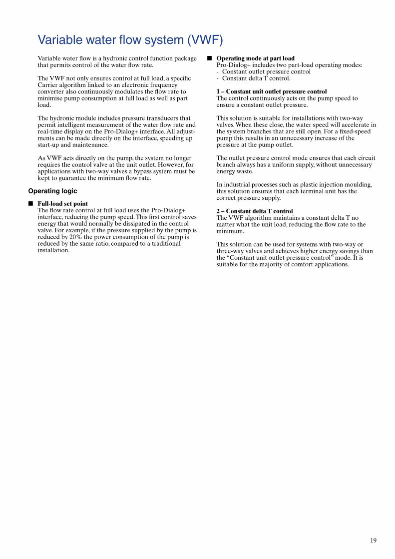
Variable water flow system (VWF)■■ Operating■mode■at■part■load
Pro-Dialog+ includes two part-load operating modes: - Constant outlet pressure control - Constant delta T control.
1■–■Constant■unit■outlet■pressure■controlThe control continuously acts on the pump speed to ensure a constant outlet pressure.
This solution is suitable for installations with two-way valves. When these close, the water speed will accelerate in the system branches that are still open. For a fixed-speed pump this results in an unnecessary increase of the pressure at the pump outlet.
The outlet pressure control mode ensures that each circuit branch always has a uniform supply, without unnecessary energy waste.
In industrial processes such as plastic injection moulding, this solution ensures that each terminal unit has the correct pressure supply.
2■–■Constant■delta■T■controlThe VWF algorithm maintains a constant delta T no matter what the unit load, reducing the flow rate to the minimum.
This solution can be used for systems with two-way or three-way valves and achieves higher energy savings than the “Constant unit outlet pressure control” mode. It is suitable for the majority of comfort applications.
Variable water flow is a hydronic control function package that permits control of the water flow rate.
The VWF not only ensures control at full load, a specific Carrier algorithm linked to an electronic frequency converter also continuously modulates the flow rate to minimise pump consumption at full load as well as part load.
The hydronic module includes pressure transducers that permit intelligent measurement of the water flow rate and real-time display on the Pro-Dialog+ interface. All adjust-ments can be made directly on the interface, speeding up start-up and maintenance.
As VWF acts directly on the pump, the system no longer requires the control valve at the unit outlet. However, for applications with two-way valves a bypass system must be kept to guarantee the minimum flow rate.
Operating logic
■■ Full-load■set■pointThe flow rate control at full load uses the Pro-Dialog+ interface, reducing the pump speed. This first control saves energy that would normally be dissipated in the control valve. For example, if the pressure supplied by the pump is reduced by 20% the power consumption of the pump is reduced by the same ratio, compared to a traditional installation.

Order No.: 13470-20.10.2012. Supersedes order No.: 13470-20.08.2010. Manufactured by: Carrier SpA, Villasanta, Italy.Manufacturer reserves the right to change any product specifications without notice. Printed in the Eurpean Union.
Environmental Management
Systems