studiul preciziei de taiere prin edm cu fir
TRANSCRIPT
8/8/2019 Studiul Preciziei de Taiere Prin EDM Cu Fir
http://slidepdf.com/reader/full/studiul-preciziei-de-taiere-prin-edm-cu-fir 1/23
Study of EDM wire cutting precision.
Abstract
Wire electro discharge machining (WEDM) has become one of the most popular processes for
producing precise geometries in hard materials, such as those used in the tooling industry. The
so-called taper-cutting involves the generation of inclined ruled surfaces, and it is especially
important in the manufacturing of tooling requiring draft angles. In this paper a new approach to
the prediction of angular error in wire-EDM taper-cutting is presented. A systematic analysis of
the influence of process parameters on angular error is carried out using Design of Experiments
(DoE) techniques. A quadratic equation for the prediction of angular error that takes into account
electrical parameters and part geometry is derived. Validation results reveal a dominant influence
of the mechanical behaviour of the wire, rather than that of EDM regime. Following this
assertion an original finite element model (FEM) to describe the mechanical behaviour of soft
wires, typically used in taper-cutting operations, has been developed taking into account non-
linear phenomena such as contact mechanics, plastic behaviour, stress-stiffening and large
displacements. Both the results of DoE techniques and FEM simulation have been validated
through experimental tests in industrial conditions.
1. Introduction to WEDM taper-cutting
The electro discharge machining (EDM) process is, by far, the most popular amongst the non-
conventional machining methods. The EDM process removes material by a series of discrete
electrical discharges that cause localised temperatures high enough to melt or vaporise the metal
in the immediate vicinity of the discharge. The only requirement is that both electrode and
workpiece materials are electrically conductive. The discharges occur between the tool
(electrode) and the workpiece in a dielectric medium under voltage drops over 20 V. This means
that there is no contact between electrode and workpiece. The distance between both (gap) is
occupied by the dielectric fluid. Since material removal is not carried out by the mechanical
action of a cutting or abrasive tool, the EDM process can be used independently on the
mechanical properties of the workpiece material; for instance, no matter how high its hardness is.
1
8/8/2019 Studiul Preciziei de Taiere Prin EDM Cu Fir
http://slidepdf.com/reader/full/studiul-preciziei-de-taiere-prin-edm-cu-fir 2/23
Therefore, the process has become very popular in the tool-making industry, in which complex
geometries with tight tolerances must be generated on difficult-to-machine materials.
Although the sinking electro discharge machining (SEDM) process was the first one to appear in
industry, the last decade has seen a large growth in the development of the wire electro discharge
machining process (WEDM). In this case a small-diameter wire (below 0.33 mm dia) is used as
electrode to cut a narrow channel in the work. The workpiece is fed continuously and slowly past
the wire in order to achieve the desired cutting path. Numerical control is used to control the
relative motion between wire and workpiece during cutting. As it cuts, the wire is continuously
advanced between spools to present a constant-diameter electrode to the work. Amongst the
typical applications of the WEDM process one can find high precision stamping dies, extrusiondies, wire drawing dies, etc.
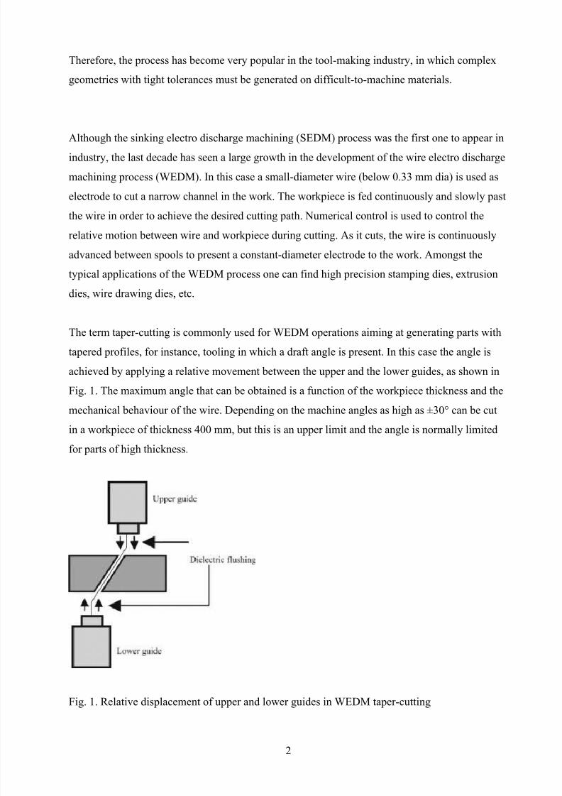
The term taper-cutting is commonly used for WEDM operations aiming at generating parts with
tapered profiles, for instance, tooling in which a draft angle is present. In this case the angle is
achieved by applying a relative movement between the upper and the lower guides, as shown in
Fig. 1. The maximum angle that can be obtained is a function of the workpiece thickness and the
mechanical behaviour of the wire. Depending on the machine angles as high as ±30° can be cut
in a workpiece of thickness 400 mm, but this is an upper limit and the angle is normally limited
for parts of high thickness.
Fig. 1. Relative displacement of upper and lower guides in WEDM taper-cutting
2
8/8/2019 Studiul Preciziei de Taiere Prin EDM Cu Fir
http://slidepdf.com/reader/full/studiul-preciziei-de-taiere-prin-edm-cu-fir 3/23
Accuracy and modelling in WEDM are recognised [1] as key research lines for the next years,
since the requirements of tolerances and surface finish imposed by industries such as tool
making or micromechanics are growing day by day.
For a better understanding of the causes of lack of accuracy, the mechanics of the process must
be analysed. With the wire subjected to tensile stress, the deformation induced on it during the
process depends on factors such as the cutting conditions, whether it is a roughing or a finishing
cut, the geometry being machined and, of course, the mechanical properties of the wire. In the
case of taper-cutting, the deformation caused by the rigidity of the wire when forced to generate
a given angle is also of primary importance.
As far as cutting regime and conditions are concerned, different authors [2], [3], [4] and [5] haveidentified the nature of the forces that cause the flexion (static component) and vibration
(dynamic component) of the wire: electrostatic force, electromagnetic force, electrodynamic
force, the force exerted by the pressure of the dielectric, and of course, the tensile force imposed
on the wire by the machine itself. Much research work has been devoted to the modelling of
these effects. In [6] and [7] models to study the effect of the dynamic components of the forces
can be found. Experimental modal analysis has also been used [8]. Research efforts have also
been devoted to the analysis of the effects of wire deformation on workpiece accuracy [9], [10]
and [11].
In all the above cases, research work has focused on vertical WEDM, with little or none attention
paid on WEDM taper-cutting. However, in the last decade a number of research works dealing
with this operation has been published. Attention has been paid at the problems that arise in the
CAD definition of the generated ruled surfaces [12] and [13]. On-line adjustment of the axial
force imposed on the wire as a function of the quality of the discharges during taper-cutting has
been recently proposed by Chiu [14].
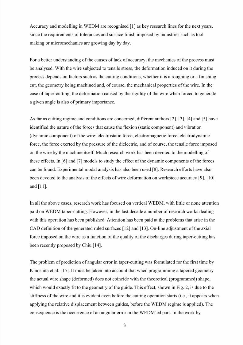
The problem of prediction of angular error in taper-cutting was formulated for the first time by
Kinoshita et al. [15]. It must be taken into account that when programming a tapered geometry
the actual wire shape (deformed) does not coincide with the theoretical (programmed) shape,
which would exactly fit to the geometry of the guide. This effect, shown in Fig. 2, is due to the
stiffness of the wire and it is evident even before the cutting operation starts (i.e., it appears when
applying the relative displacement between guides, before the WEDM regime is applied). The
consequence is the occurrence of an angular error in the WEDM’ed part. In the work by
3
8/8/2019 Studiul Preciziei de Taiere Prin EDM Cu Fir
http://slidepdf.com/reader/full/studiul-preciziei-de-taiere-prin-edm-cu-fir 4/23
Kinoshita, the influence of wire stiffness is considered using the differential equation for the
static deflection of an elastic beam that can be written as follows (see also Fig. 2):
where E is the Young modulus of the wire; I, the momentum of inertia of the wire; TW, the axial
force imposed on the wire by the machine; FA, the normal force at point A; and MA, the bending
moment at point A. The boundary conditions and the resolution for the second-order ordinary
differential equation can be found in [15]. Using this approach an estimation of the angular error
caused by the deformation of the wire can be obtained, and from that theoretical value,
corrections to the position of the guides can be introduced in the Numerical Control of the
machine in order to compensate the error [16]. It must be pointed out again that this approach
does not include the effect of EDM regime on the prediction of angular error. This fact is also
recognised by a recent patent [17], in which the position of guides is corrected using the data
obtained from calibration carried out using precision tooling, and performed previous to cutting
(i.e., with no EDM forces acting on the wire).
Fig. 2. Deformation of the wire in taper-cutting due to rigidity. Forces and momentum acting on
the wire (after Kinoshita et al. [15]).
4
8/8/2019 Studiul Preciziei de Taiere Prin EDM Cu Fir
http://slidepdf.com/reader/full/studiul-preciziei-de-taiere-prin-edm-cu-fir 5/23
The model proposed in [15] has been programmed for the case of a soft wire and used in a set of
industrial experiments in order to assess its validity. A wire commonly used nowadays for taper-
cutting, the coated Broncocut-W® (by Bedra), diameter 0.25 mm, has been used. This wire is
considered as soft due to its low yield strength and high elongation. Mechanical characteristics of
the wire, obtained from tensile tests, can be found in Table 1. Angular error has been predicted
by solving Eq. (1) using the mechanical properties of the wire, and the value of the error has then
been used to compensate the position of the wire guides as described in [16]. Machining tests
using the compensated location of the guides have then been carried out on an ONA Prima E-
250 WEDM machine to know the degree of accuracy that can be obtained on a test part using the
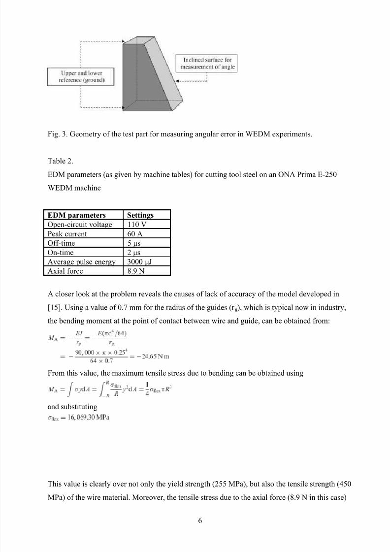
approach by Kinoshita. Work material is AISI D2 tool steel. The geometry of the test part is
shown in Fig. 3, and the angle of the inclined surface is measured with respect to the ground
surfaces using a Zeiss 850 CNC coordinate measuring machine. WEDM conditions have beenestablished by machine table look-up, and they are collected in Table 2. In the experiments errors
over 30′ have been measured. This value can be compared with what can be considered an
‘exact’ experimental method. This latter involves cutting the test part without any compensation
of the location of the guides and measuring the angular error. The so-measured value of the
error, which is considered ‘exact’ because includes both the effect of wire deformation and
WEDM regime, is then used to calculate the corrected position of the guides that will be used in
the new machining test. Under this approach angular errors below 3′ can be achieved. If this
value is compared with the one obtained using the linear model (as said above, 30′), it becomes
obvious that improvements in theoretical prediction of angular error are required.
Table 1.
Mechanical characteristics of the Broncocut-W® (by Bedra) wire used for the study
Mechanical properties Broncocut-W™ (by Bedra)Wire composition Base material: CuZn20
Coating: CuZn50Tensile strength, σr (MPa) 450
Yield strength, σf (MPa) 255
Young modulus, E (MPa) 90,000
Elongation, εr 30
Poisson coefficient, υ 0.33
5
8/8/2019 Studiul Preciziei de Taiere Prin EDM Cu Fir
http://slidepdf.com/reader/full/studiul-preciziei-de-taiere-prin-edm-cu-fir 6/23
Fig. 3. Geometry of the test part for measuring angular error in WEDM experiments.
Table 2.
EDM parameters (as given by machine tables) for cutting tool steel on an ONA Prima E-250
WEDM machine
EDM parameters SettingsOpen-circuit voltage 110 V
Peak current 60 A
Off-time 5 μs
On-time 2 μs
Average pulse energy 3000 μJ
Axial force 8.9 N
A closer look at the problem reveals the causes of lack of accuracy of the model developed in
[15]. Using a value of 0.7 mm for the radius of the guides (r g), which is typical now in industry,
the bending moment at the point of contact between wire and guide, can be obtained from:
From this value, the maximum tensile stress due to bending can be obtained using
and substituting
This value is clearly over not only the yield strength (255 MPa), but also the tensile strength (450
MPa) of the wire material. Moreover, the tensile stress due to the axial force (8.9 N in this case)
6
8/8/2019 Studiul Preciziei de Taiere Prin EDM Cu Fir
http://slidepdf.com/reader/full/studiul-preciziei-de-taiere-prin-edm-cu-fir 7/23
imposed by the machine on the wire must be added to this value. From this simple calculus it can
be deduced that the model erroneously predicts wire breakage, and only 0.071% of the wire
section works still within the elastic region. Analysis of wire's mechanical behaviour leads to the
conclusion that important effects, non-linear in nature, have not been considered in the elastic
model such as the plastic behaviour of the soft wires of low yield strength and high elongation,
the local effects imposed by the high curvature of the geometry currently used for the guides, the
large displacements between the original (vertical) and the deformed (tapered) situations, the
influence of stress-stiffening, and the effect of friction. In addition, the model for the mechanical
behaviour of the wire does not take into account the effect of cutting regime on the results.
At the sight of the above comments it can be said that still important research work must be
carried out for a better understanding of the sources of angular error in wire-EDM taper-cutting.An analysis of the influence of process variables on the deviations is the previous step towards
theoretical prediction of the error that can then be corrected as it has been described in this
section. In this work an original contribution to the analysis of the factors that influence angular
error in taper-cutting that leads to the development of experimental and numerical methods for
the prediction of the error is presented. Section 2 introduces an experimental analysis based on
Design of Experiments (DoE) techniques. In Sections 3 and 4, finite element simulation of the
mechanical behaviour of a wire typically used for taper-cutting is presented. The models are
validated in industrial conditions and from the work carried out, conclusions are drawn.
2. Experimental analysis of the influence of process parameters on angular error in WEDM
taper-cutting
In this section a systematic approach of analysis based on DoE techniques is presented. The
Central Composite Rotatable Design method has been selected to obtain the degree of influence
of the different variables and to derive a mathematical expression that relates angular error and
process variables.
Prior to applying DoE techniques, the input variables must be chosen. Five variables were
selected: part thickness (H), angle (α), off-time (t0), pulse energy (E) and open-circuit voltage
(U0). Part thickness and angle are related to the geometrical description of the problem; off-time,
pulse energy and open-circuit voltage are related to the EDM regime and as explained in
previously published literature, to the forces exerted during the process. Table 3 collects the
ranges of maximum and minimum values used for each variable in the DoE. In the case of the
7
8/8/2019 Studiul Preciziei de Taiere Prin EDM Cu Fir
http://slidepdf.com/reader/full/studiul-preciziei-de-taiere-prin-edm-cu-fir 8/23
wire-EDM parameters, the range has been selected wide enough to be able to take into account
very different machining cases. For instance, for a WEDM operator that usually cuts tool steel,
values of off-time of 80 μs can be surprisingly high. However, these values are compulsory when
EDM’ing advanced materials such as low conductivity ceramics (for instance, boron carbide
[18]). The same applies to the other electrical parameters. Therefore, the aim has been to cover a
very wide range of possible EDM conditions.
Table 3.
Ranges of values used for the selected variables in the Design of Experiments
Variables for the DoE Range of variation
Part thickness, H (mm) 10–80
Taper angle, α (°) 5–30
Off-time, t0 (ms) 5–80Pulse energy, E (μJ) 2500–6000
Open-circuit voltage, U0 (V) 110–150
The experiments were carried out using the same work material and WEDM machine as
described in Section 1. Thus, a Hadamard matrix design with 16 trials, 10 star points and six
centre points must be built, which involves carrying out 32 tests. This approach is capable of
representing the influence of the variables and the interactions between them. Machining tests
involve cutting and measuring the test-part geometry shown in Fig. 3. The complete set of teststogether with the results of the angle measured in each one is shown in Table 4.
Table 4.
Complete set of tests for the DoE methodology
Experiment no. H (mm) α (°) t0 (μs) E (μJ) U0 (V) Measured angle (°)1 27.5 11°15′ 23.75 5125 140 11°40′48″
2 27.5 11°15′ 61.25 3375 140 11°42′
3 62.5 11°15′ 61.25 5125 140 11°30′
4 62.5 23°45′ 61.25 3375 140 24°4′48″
5 62.5 23°45′ 61.25 5125 120 24°5′24″
…as table 4.
6 62.5 23°45′ 23.75 5125 140 24°5′24″
7 27.5 23°45′ 61.25 3375 120 24°23′24″
8 62.5 11°15′ 23.75 3375 140 11°28′12″
9 27.5 23°45 61.25 5125 140 24°19′12″
10 62.5 11°15′ 61.25 3375 120 11°29′24″
11 62.5 23°45 23.75 3375 120 24°12′
8
8/8/2019 Studiul Preciziei de Taiere Prin EDM Cu Fir
http://slidepdf.com/reader/full/studiul-preciziei-de-taiere-prin-edm-cu-fir 9/23
12 27.5 23°45 23.75 3375 140 24°13′48″
13 27.5 11°15′ 61.25 5125 120 11°39′36″
14 62.5 11°15′ 23.75 5125 120 11°27′36″
15 27.5 23°45 23.75 5125 120 24°11′14″
16 27.5 11°15′ 23.75 3375 120 11°37′12″
17 45 17°30′ 42.5 4250 110 17°49′48″
18 45 17°30′ 42.5 4250 150 17°49′48″19 45 17°30′ 5 4250 130 17°48′
20 45 17°30′ 80 4250 130 17°48′36″
21 10 17°30′ 42.5 4250 130 18°23′24″
22 80 17°30′ 42.5 4250 130 17°42′
23 45 5° 42.5 4250 130 5°10′48″
24 45 30° 42.5 4250 130 30°22′48″
25 45 17°30′ 42.5 2500 130 17°48′36″
26 45 17°30′ 42.5 6000 130 17°52′48″
27 45 17°30′ 42.5 4250 130 17°52′48″
28 45 17°30′ 42.5 4250 130 17°54′29 45 17°30′ 42.5 4250 130 17°52′48″
30 45 17°30′ 42.5 4250 130 17°53′24″
31 45 17°30′ 42.5 4250 130 17°52′48″
32 45 17°30′ 42.5 4250 130 17°53′24″
The results for each test have also been included in the last column of the table.
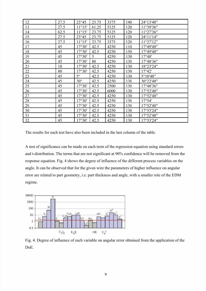
A test of significance can be made on each term of the regression equation using standard errors
and t-distribution. The terms that are not significant at 90% confidence will be removed from the
response equation. Fig. 4 shows the degree of influence of the different process variables on the
angle. It can be observed that for the given wire the parameters of higher influence on angular
error are related to part geometry, i.e. part thickness and angle, with a smaller role of the EDM
regime.
Fig. 4. Degree of influence of each variable on angular error obtained from the application of the
DoE.
9
8/8/2019 Studiul Preciziei de Taiere Prin EDM Cu Fir
http://slidepdf.com/reader/full/studiul-preciziei-de-taiere-prin-edm-cu-fir 10/23
Once the variables whose influence can be neglected have been removed, an expression (Eq. (4))
that can be used to predict the actual taper angle as a function of the variables involved in the
process can be obtained:
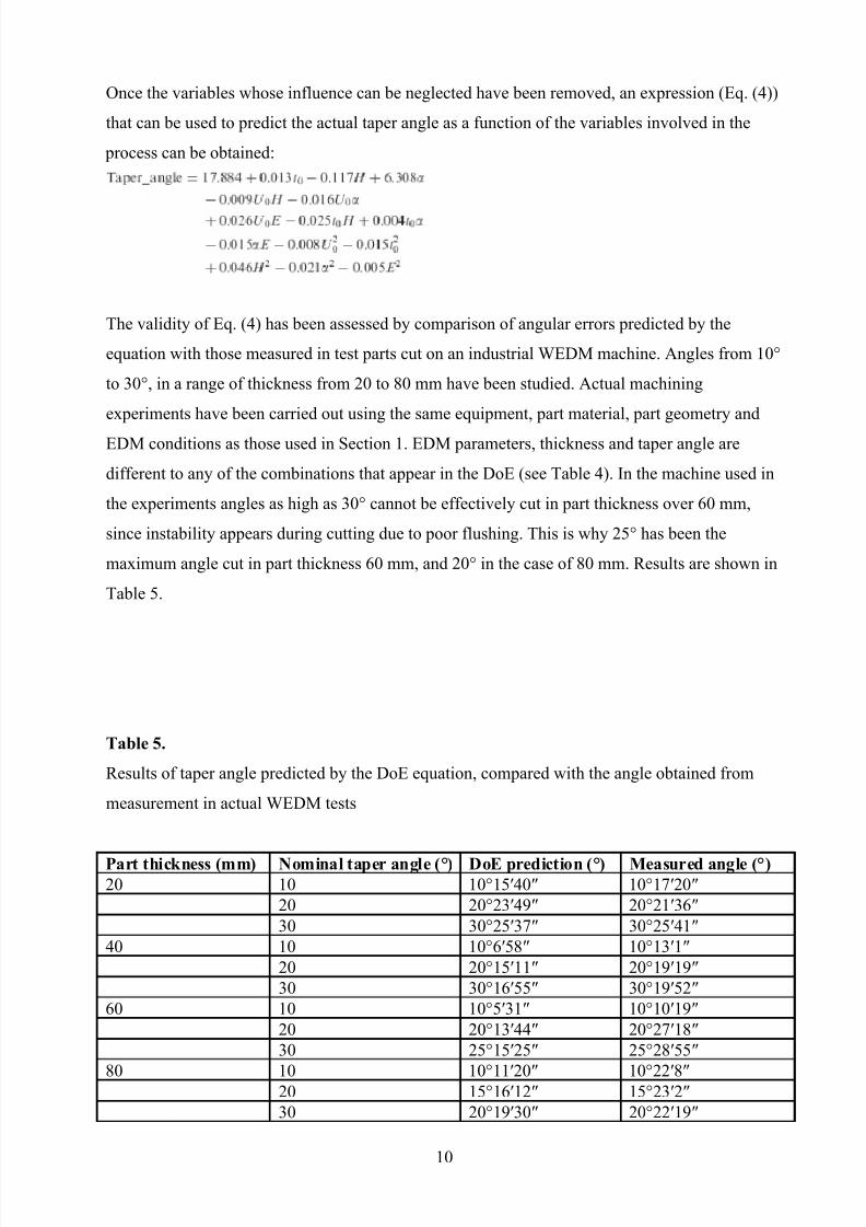
The validity of Eq. (4) has been assessed by comparison of angular errors predicted by the
equation with those measured in test parts cut on an industrial WEDM machine. Angles from 10°
to 30°, in a range of thickness from 20 to 80 mm have been studied. Actual machining
experiments have been carried out using the same equipment, part material, part geometry and
EDM conditions as those used in Section 1. EDM parameters, thickness and taper angle are
different to any of the combinations that appear in the DoE (see Table 4). In the machine used in
the experiments angles as high as 30° cannot be effectively cut in part thickness over 60 mm,
since instability appears during cutting due to poor flushing. This is why 25° has been the
maximum angle cut in part thickness 60 mm, and 20° in the case of 80 mm. Results are shown in
Table 5.
Table 5.
Results of taper angle predicted by the DoE equation, compared with the angle obtained from
measurement in actual WEDM tests
Part thickness (mm) Nominal taper angle (°) DoE prediction (°) Measured angle (°)20 10 10°15′40″ 10°17′20″
20 20°23′49″ 20°21′36″
30 30°25′37″ 30°25′41″
40 10 10°6′58″ 10°13′1″
20 20°15′11″ 20°19′19″
30 30°16′55″ 30°19′52″
60 10 10°5′31″ 10°10′19″
20 20°13′44″ 20°27′18″
30 25°15′25″ 25°28′55″
80 10 10°11′20″ 10°22′8″20 15°16′12″ 15°23′2″
30 20°19′30″ 20°22′19″
10
8/8/2019 Studiul Preciziei de Taiere Prin EDM Cu Fir
http://slidepdf.com/reader/full/studiul-preciziei-de-taiere-prin-edm-cu-fir 11/23
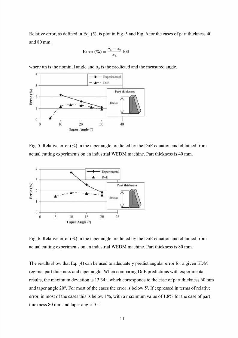
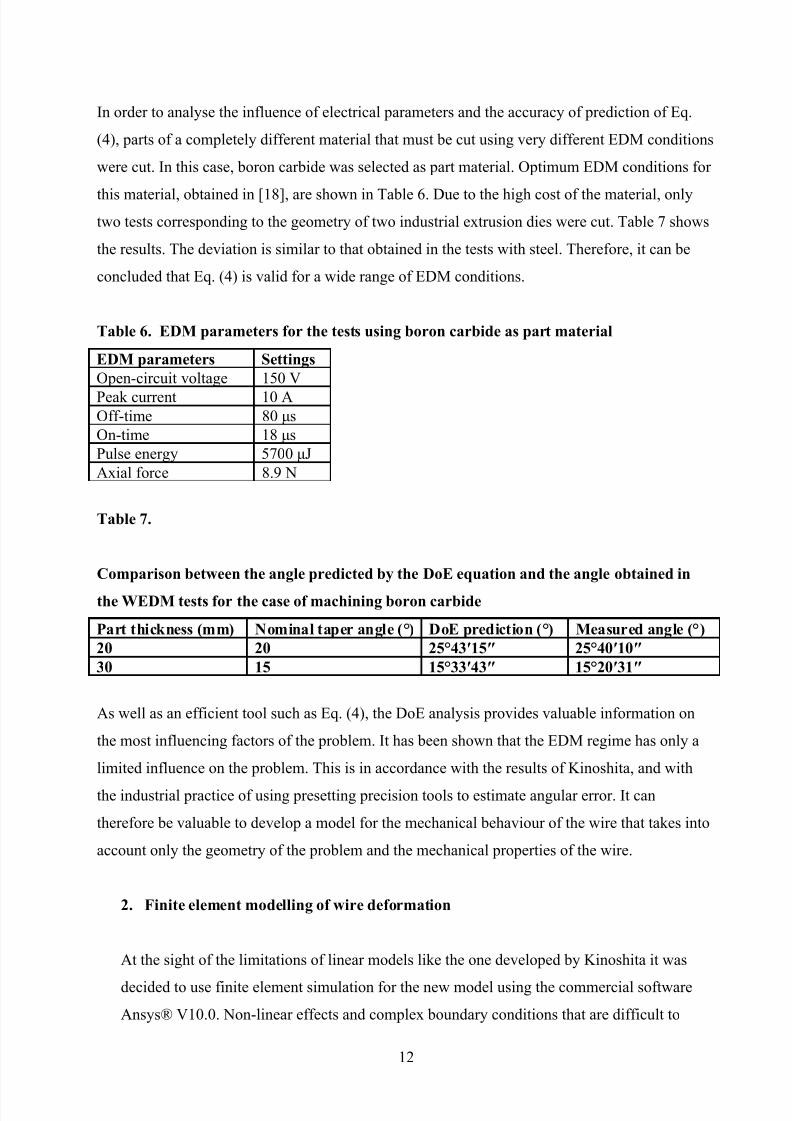
Relative error, as defined in Eq. (5), is plot in Fig. 5 and Fig. 6 for the cases of part thickness 40
and 80 mm.
where αn is the nominal angle and α p is the predicted and the measured angle.
Fig. 5. Relative error (%) in the taper angle predicted by the DoE equation and obtained from
actual cutting experiments on an industrial WEDM machine. Part thickness is 40 mm.
Fig. 6. Relative error (%) in the taper angle predicted by the DoE equation and obtained from
actual cutting experiments on an industrial WEDM machine. Part thickness is 80 mm.
The results show that Eq. (4) can be used to adequately predict angular error for a given EDM
regime, part thickness and taper angle. When comparing DoE predictions with experimental
results, the maximum deviation is 13′34″, which corresponds to the case of part thickness 60 mm
and taper angle 20°. For most of the cases the error is below 5′. If expressed in terms of relative
error, in most of the cases this is below 1%, with a maximum value of 1.8% for the case of part
thickness 80 mm and taper angle 10°.
11
8/8/2019 Studiul Preciziei de Taiere Prin EDM Cu Fir
http://slidepdf.com/reader/full/studiul-preciziei-de-taiere-prin-edm-cu-fir 12/23
In order to analyse the influence of electrical parameters and the accuracy of prediction of Eq.
(4), parts of a completely different material that must be cut using very different EDM conditions
were cut. In this case, boron carbide was selected as part material. Optimum EDM conditions for
this material, obtained in [18], are shown in Table 6. Due to the high cost of the material, only
two tests corresponding to the geometry of two industrial extrusion dies were cut. Table 7 shows
the results. The deviation is similar to that obtained in the tests with steel. Therefore, it can be
concluded that Eq. (4) is valid for a wide range of EDM conditions.
Table 6. EDM parameters for the tests using boron carbide as part material
EDM parameters SettingsOpen-circuit voltage 150 V
Peak current 10 AOff-time 80 μs
On-time 18 μs
Pulse energy 5700 μJ
Axial force 8.9 N
Table 7.
Comparison between the angle predicted by the DoE equation and the angle obtained in
the WEDM tests for the case of machining boron carbide
Part thickness (mm) Nominal taper angle (°) DoE prediction (°) Measured angle (°)20 20 25°43′15″ 25°40′10″30 15 15°33′43″ 15°20′31″
As well as an efficient tool such as Eq. (4), the DoE analysis provides valuable information on
the most influencing factors of the problem. It has been shown that the EDM regime has only a
limited influence on the problem. This is in accordance with the results of Kinoshita, and with
the industrial practice of using presetting precision tools to estimate angular error. It can
therefore be valuable to develop a model for the mechanical behaviour of the wire that takes into
account only the geometry of the problem and the mechanical properties of the wire.
2. Finite element modelling of wire deformation
At the sight of the limitations of linear models like the one developed by Kinoshita it was
decided to use finite element simulation for the new model using the commercial software
Ansys® V10.0. Non-linear effects and complex boundary conditions that are difficult to
12
8/8/2019 Studiul Preciziei de Taiere Prin EDM Cu Fir
http://slidepdf.com/reader/full/studiul-preciziei-de-taiere-prin-edm-cu-fir 13/23
account for using analytical methods can be included using numerical simulation. The
following assumptions have been considered when developing the model:
• The effect of the forces acting on the wire due to the EDM regime is not included. The
only external force is the axial force imposed by the machine itself.
• Only the upper-half of the wire has been modelled. It is assumed that the behaviour in
the lower half will be identical.
• Vertical displacement of the upper-end section of the wire is avoided.
• The lower-end of the upper-half of the wire is displaced horizontally to the ideal centre
point of the problem, i.e., the point at an equal horizontal distance from both guides.
• Plastic behaviour of the wire is considered.
• The Augmented Lagrangian algorithm has been used to solve the problem of contact.
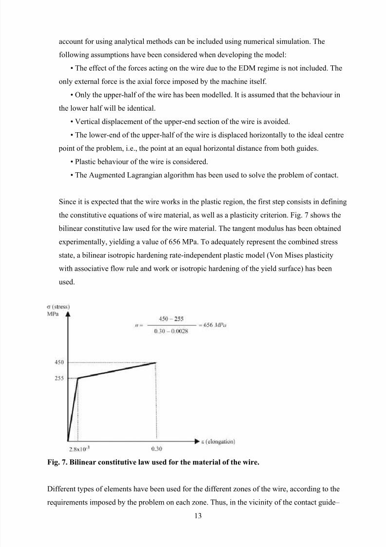
Since it is expected that the wire works in the plastic region, the first step consists in defining
the constitutive equations of wire material, as well as a plasticity criterion. Fig. 7 shows the
bilinear constitutive law used for the wire material. The tangent modulus has been obtained
experimentally, yielding a value of 656 MPa. To adequately represent the combined stress
state, a bilinear isotropic hardening rate-independent plastic model (Von Mises plasticity
with associative flow rule and work or isotropic hardening of the yield surface) has been
used.
Fig. 7. Bilinear constitutive law used for the material of the wire.
Different types of elements have been used for the different zones of the wire, according to the
requirements imposed by the problem on each zone. Thus, in the vicinity of the contact guide–
13
8/8/2019 Studiul Preciziei de Taiere Prin EDM Cu Fir
http://slidepdf.com/reader/full/studiul-preciziei-de-taiere-prin-edm-cu-fir 14/23
wire linear hexahedrons have been used. On the one hand, the geometry is simple enough not to
require higher-order elements of curved faces. On the other hand, if element size is small
enough, the approach given by linear elements is good enough while reducing processing time
because of the limited number of nodes. Mesh density has been made higher at the zone at which
contact wire–guide will occur, so that contact elements of enough resolution can be applied on
that zone. In the zone in which plastic behaviour is not expected, that is, far from the zone of
contact with the guide, 3D elastic beams have been used. These elements have two nodes per
element and 6 degrees of freedom (dof) per node. Since three of these dofs are rotational in the
nodes of the beam, and only translational dof is present in the 3D plastic hexahedrons, an
additional condition of continuity must be implemented in the section where these two types of
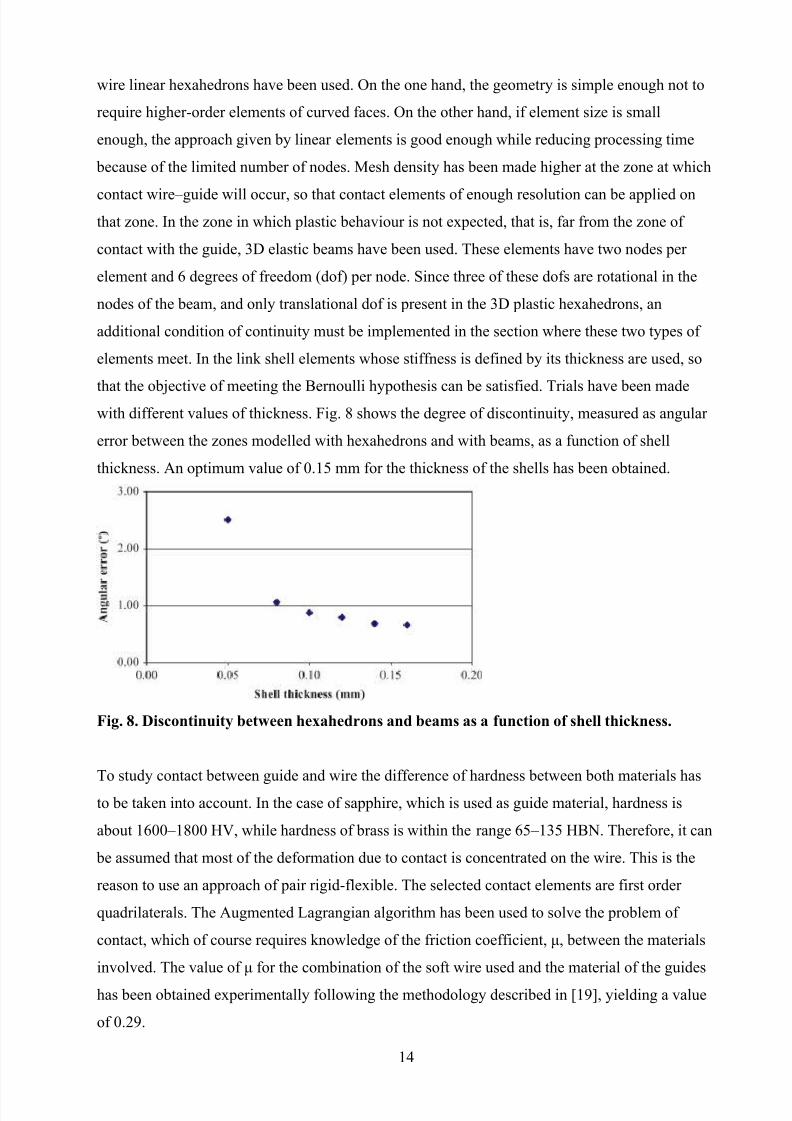
elements meet. In the link shell elements whose stiffness is defined by its thickness are used, so
that the objective of meeting the Bernoulli hypothesis can be satisfied. Trials have been madewith different values of thickness. Fig. 8 shows the degree of discontinuity, measured as angular
error between the zones modelled with hexahedrons and with beams, as a function of shell
thickness. An optimum value of 0.15 mm for the thickness of the shells has been obtained.
Fig. 8. Discontinuity between hexahedrons and beams as a function of shell thickness.
To study contact between guide and wire the difference of hardness between both materials has
to be taken into account. In the case of sapphire, which is used as guide material, hardness is
about 1600–1800 HV, while hardness of brass is within the range 65–135 HBN. Therefore, it can
be assumed that most of the deformation due to contact is concentrated on the wire. This is the
reason to use an approach of pair rigid-flexible. The selected contact elements are first order
quadrilaterals. The Augmented Lagrangian algorithm has been used to solve the problem of
contact, which of course requires knowledge of the friction coefficient, μ, between the materials
involved. The value of μ for the combination of the soft wire used and the material of the guides
has been obtained experimentally following the methodology described in [19], yielding a value
of 0.29.
14
8/8/2019 Studiul Preciziei de Taiere Prin EDM Cu Fir
http://slidepdf.com/reader/full/studiul-preciziei-de-taiere-prin-edm-cu-fir 15/23
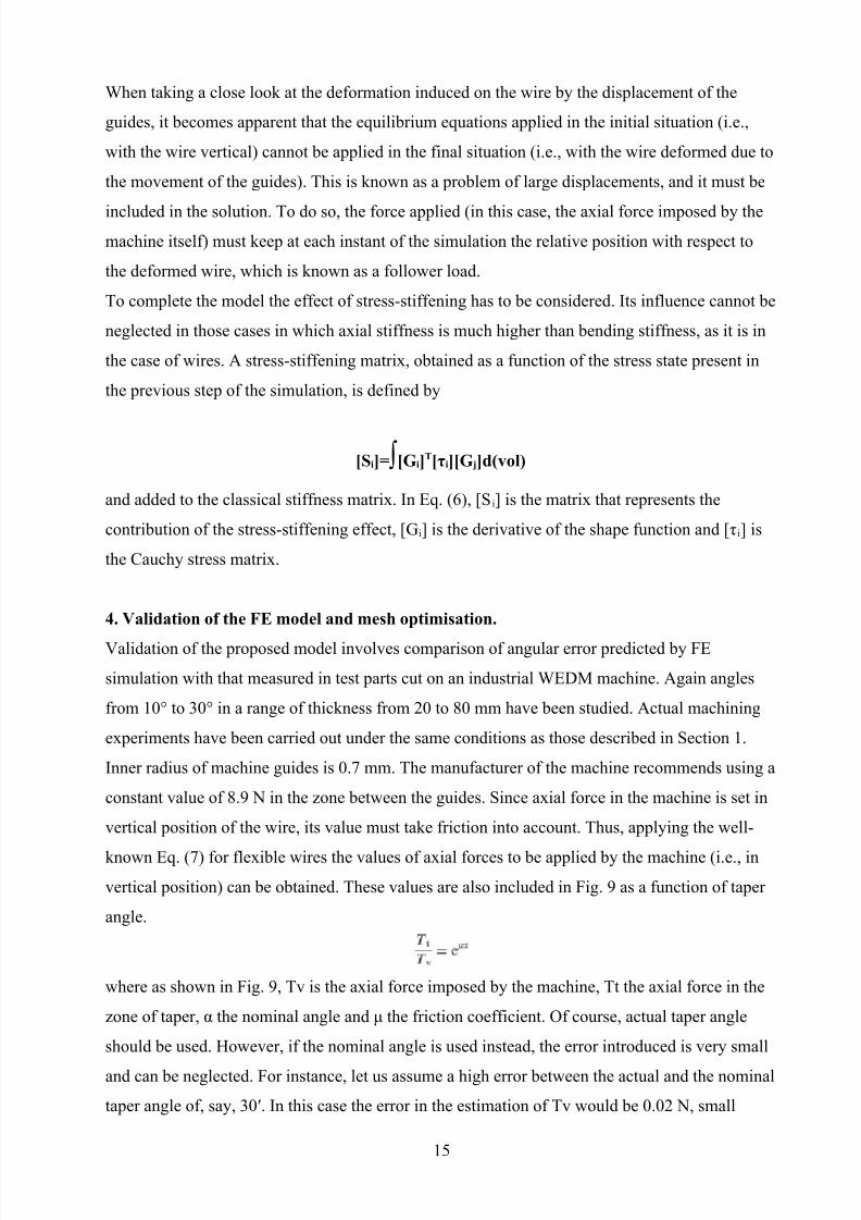
When taking a close look at the deformation induced on the wire by the displacement of the
guides, it becomes apparent that the equilibrium equations applied in the initial situation (i.e.,
with the wire vertical) cannot be applied in the final situation (i.e., with the wire deformed due to
the movement of the guides). This is known as a problem of large displacements, and it must be
included in the solution. To do so, the force applied (in this case, the axial force imposed by the
machine itself) must keep at each instant of the simulation the relative position with respect to
the deformed wire, which is known as a follower load.
To complete the model the effect of stress-stiffening has to be considered. Its influence cannot be
neglected in those cases in which axial stiffness is much higher than bending stiffness, as it is in
the case of wires. A stress-stiffening matrix, obtained as a function of the stress state present in
the previous step of the simulation, is defined by
[Si]=∫[Gi]T[τi][G j]d(vol)
and added to the classical stiffness matrix. In Eq. (6), [S i] is the matrix that represents the
contribution of the stress-stiffening effect, [Gi] is the derivative of the shape function and [τi] is
the Cauchy stress matrix.
4. Validation of the FE model and mesh optimisation.
Validation of the proposed model involves comparison of angular error predicted by FE
simulation with that measured in test parts cut on an industrial WEDM machine. Again angles
from 10° to 30° in a range of thickness from 20 to 80 mm have been studied. Actual machining
experiments have been carried out under the same conditions as those described in Section 1.
Inner radius of machine guides is 0.7 mm. The manufacturer of the machine recommends using a
constant value of 8.9 N in the zone between the guides. Since axial force in the machine is set in
vertical position of the wire, its value must take friction into account. Thus, applying the well-
known Eq. (7) for flexible wires the values of axial forces to be applied by the machine (i.e., in
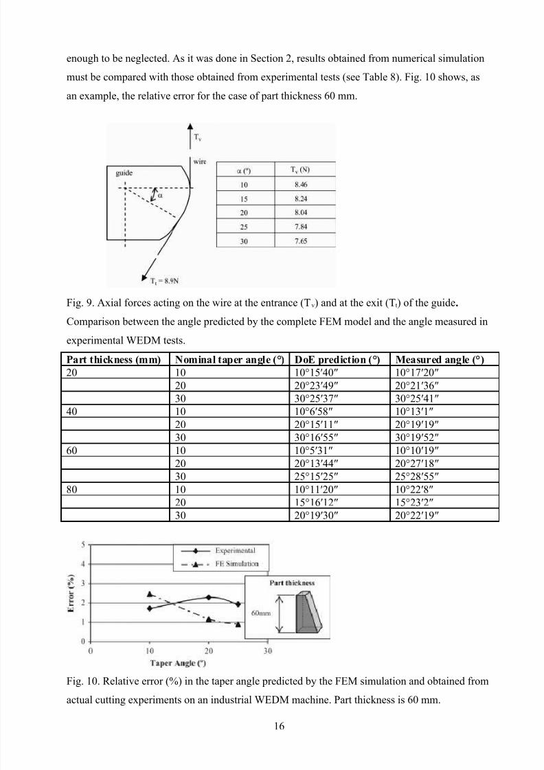
vertical position) can be obtained. These values are also included in Fig. 9 as a function of taper
angle.
where as shown in Fig. 9, Tv is the axial force imposed by the machine, Tt the axial force in the
zone of taper, α the nominal angle and μ the friction coefficient. Of course, actual taper angle
should be used. However, if the nominal angle is used instead, the error introduced is very small
and can be neglected. For instance, let us assume a high error between the actual and the nominal
taper angle of, say, 30′. In this case the error in the estimation of Tv would be 0.02 N, small
15
8/8/2019 Studiul Preciziei de Taiere Prin EDM Cu Fir
http://slidepdf.com/reader/full/studiul-preciziei-de-taiere-prin-edm-cu-fir 16/23
enough to be neglected. As it was done in Section 2, results obtained from numerical simulation
must be compared with those obtained from experimental tests (see Table 8). Fig. 10 shows, as
an example, the relative error for the case of part thickness 60 mm.
Fig. 9. Axial forces acting on the wire at the entrance (T v) and at the exit (Tt) of the guide.
Comparison between the angle predicted by the complete FEM model and the angle measured in
experimental WEDM tests.
Part thickness (mm) Nominal taper angle (°) DoE prediction (°) Measured angle (°)20 10 10°15′40″ 10°17′20″
20 20°23′49″ 20°21′36″
30 30°25′37″ 30°25′41″
40 10 10°6′58″ 10°13′1″
20 20°15′11″ 20°19′19″
30 30°16′55″ 30°19′52″
60 10 10°5′31″ 10°10′19″
20 20°13′44″ 20°27′18″
30 25°15′25″ 25°28′55″
80 10 10°11′20″ 10°22′8″
20 15°16′12″ 15°23′2″
30 20°19′30″ 20°22′19″
Fig. 10. Relative error (%) in the taper angle predicted by the FEM simulation and obtained from
actual cutting experiments on an industrial WEDM machine. Part thickness is 60 mm.
16
8/8/2019 Studiul Preciziei de Taiere Prin EDM Cu Fir
http://slidepdf.com/reader/full/studiul-preciziei-de-taiere-prin-edm-cu-fir 17/23
Errors are now higher, in general, than those obtained when using the DoE predictions. In many
cases, the error is over 10′, with a maximum value of 14′36″ for the case of thickness 60 mm and
taper angle 25′. If expressed in terms of relative error, the maximum is about 2%. The deviation
between FEM and DoE predictions can be explained if one takes into account that FEM
simulation does not consider the effect of EDM regime on angular error. Results also show that
deviation between the two methods of prediction are not very high, confirming the fact that most
of the error is due to the mechanical behaviour of the wire and, to a lesser extent, to the EDM
regime.
Prediction of angular error obtained from FE simulation has been used in scattered WED
machining tests to correct the location of the guides (following the procedure given in [16]), andthus improve angular accuracy of parts. The results are collected in Table 9. After compensation,
angular error in most cases is below 2′, with a maximum value of 3′28″. If compared with the
results obtained by the experimental method commented in Section 1, that exhibited errors about
3′, it can be said that the numerical method achieves an excellent degree of accuracy. It must be
beard in mind that the procedure for correction of the position of the guides only accounts for the
component of deformation of the wire due to its rigidity, neglecting the influence of phenomena
such as wire vibration.
Table 9.
Results of taper angle measured in WEDM’ed parts after guide location compensation is
performed using the values of angular error predicted by the complete FE model.
Part thickness (mm) Nominal taper angle (°) Measured angle in WEDM tests (°)20 28 28°1′57″
40 14 13°59′28″40 26 26°0′15″60 11 10°58′8″60 20 20°1′52″80 8 7°56′32″80 19 19°2′21″
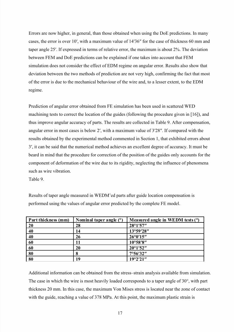
Additional information can be obtained from the stress–strain analysis available from simulation.
The case in which the wire is most heavily loaded corresponds to a taper angle of 30°, with part
thickness 20 mm. In this case, the maximum Von Mises stress is located near the zone of contactwith the guide, reaching a value of 378 MPa. At this point, the maximum plastic strain is
17
8/8/2019 Studiul Preciziei de Taiere Prin EDM Cu Fir
http://slidepdf.com/reader/full/studiul-preciziei-de-taiere-prin-edm-cu-fir 18/23
18.85%. Therefore, the wire is working within the plastic region but the maximum strength is not
exceeded in any case, which is a clear improvement with respect to the elastic model. Fig. 11
shows the stress distribution in the vicinity of the contact guide–wire. Results also show that
linear elastic behaviour occurs at a certain distance from the contact wire–guide, with stresses
below the yield strength of the material. This fact validates the hypothesis of having used elastic
beams for the central part of the wire, resulting in a reduction of processing time.
Fig. 11. Stress distribution predicted by the FE model for the case of part thickness 20 mm and
taper angle 30°.
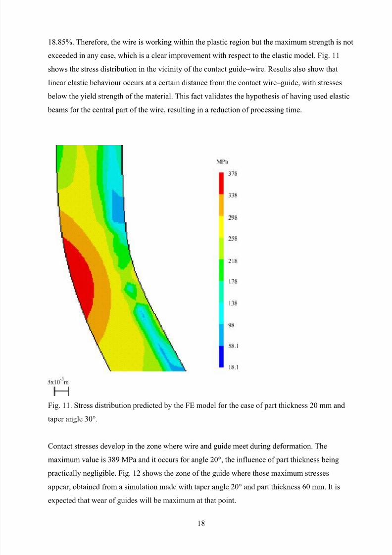
Contact stresses develop in the zone where wire and guide meet during deformation. The
maximum value is 389 MPa and it occurs for angle 20°, the influence of part thickness being
practically negligible. Fig. 12 shows the zone of the guide where those maximum stresses
appear, obtained from a simulation made with taper angle 20° and part thickness 60 mm. It is
expected that wear of guides will be maximum at that point.
18
8/8/2019 Studiul Preciziei de Taiere Prin EDM Cu Fir
http://slidepdf.com/reader/full/studiul-preciziei-de-taiere-prin-edm-cu-fir 19/23
Fig. 12. Distribution of contact stresses between wire and guide as predicted by the FE model for
the case of part thickness 60 mm and taper angle 20°.
The results above exhibit a very good degree of agreement with the actual mechanical behaviour
of the wire. On the one hand, the model is very complete and introduces the different sources of
non-linearity that have to be considered; but on the other hand, computational cost is high.
Processing time may range from 20 m in the less severely stressed cases, up to 4 h in the most
difficult cases, such as taper angle 30° and part thickness 20 mm. This is due to the high number
of elements required: 1248 hexahedrons, 10 beams and 21 shell elements. Therefore, the
possibility of using a simplified model in which processing time can be dramatically reduced
while keeping the accuracy of the results was studied, bearing in mind that, of course, using a
simpler model involves loosing some information.
19
8/8/2019 Studiul Preciziei de Taiere Prin EDM Cu Fir
http://slidepdf.com/reader/full/studiul-preciziei-de-taiere-prin-edm-cu-fir 20/23
Three-dimensional plastic beams were tested for the simplified model, so that transition shells
can be eliminated. This new type of element is quadratic, with three nodes and 6 dofs per node.
Boundary conditions are kept similar to those used in the complete model, and mesh density is
higher in the zone of contact wire–guide. The total number of elements in this case is 100.
Modelling of contact has also been made simpler: while first order quadrilaterals are used again
on the surface of the guide, modelling of the wire has been greatly simplified. Instead of using
the same type of elements, the nodes of the plastic beams have been used to define the contact,
which, keeping a similar approach, is defined as rigid-flexible.
The accuracy of the simplified model was examined by comparing the prediction of angular
error with that provided by the complete model. Simulations involving part thickness 20–80 mmand taper angle 10–30° were carried out and the evolution of angular error with respect to the
complete model was studied. From the results, collected in Table 10, it becomes clear that
although the new model is clearly simpler, accuracy is not at all lost. The deviation between both
models in the prediction of the angle is always below 1′. However, processing time with the
simplified model is drastically cut, with longest simulation runs of about 15 m.
Table 10.
Comparison between the angles predicted by the complete and the simplified finite element
models
Part thickness (mm) Nominal taper angle (°) DoE prediction (°) Measured angle (°)20 10 10°29′24″ 10°28′51″
20 20°28′56″ 20°28′39″
30 30°33′14″ 30°32′14″
40 10 10°20′5″ 10°19′42″
20 20°20′51″ 20°19′47″
30 30°19′17″ 30°18′40″
60 10 10°14′41″ 10°14′24″
20 20°14′5″ 20°13′58″
30 25°13′29″ 25°13′19″
80 10 10°11′36″ 10°11′24″
20 15°11′18″ 15°11′24″
30 20°10′49″ 20°10′48″
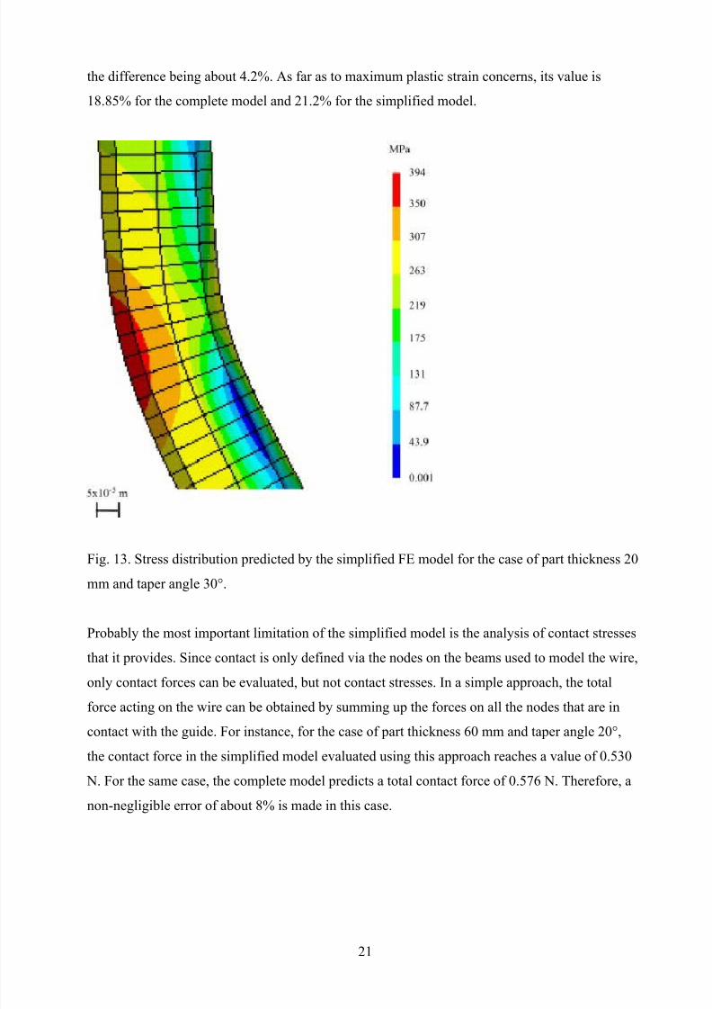
Stress analysis can also be used for comparison between models. The most severely stressed
situation, that is, the simulation run for part thickness 20 mm and taper angle 30° is shown in
Fig. 13, so that it can be compared with the results included in Fig. 11. Again, with the wire
working within the plastic region, maximum strength is not exceeded. The maximum value of
the Von Mises stress is 378 MPa for the complete model and 394 MPa for the simplified model,
20
8/8/2019 Studiul Preciziei de Taiere Prin EDM Cu Fir
http://slidepdf.com/reader/full/studiul-preciziei-de-taiere-prin-edm-cu-fir 21/23
the difference being about 4.2%. As far as to maximum plastic strain concerns, its value is
18.85% for the complete model and 21.2% for the simplified model.
Fig. 13. Stress distribution predicted by the simplified FE model for the case of part thickness 20
mm and taper angle 30°.
Probably the most important limitation of the simplified model is the analysis of contact stresses
that it provides. Since contact is only defined via the nodes on the beams used to model the wire,
only contact forces can be evaluated, but not contact stresses. In a simple approach, the total
force acting on the wire can be obtained by summing up the forces on all the nodes that are in
contact with the guide. For instance, for the case of part thickness 60 mm and taper angle 20°,
the contact force in the simplified model evaluated using this approach reaches a value of 0.530
N. For the same case, the complete model predicts a total contact force of 0.576 N. Therefore, a
non-negligible error of about 8% is made in this case.
21
8/8/2019 Studiul Preciziei de Taiere Prin EDM Cu Fir
http://slidepdf.com/reader/full/studiul-preciziei-de-taiere-prin-edm-cu-fir 22/23
5. Conclusions
In this work a study of angular error in WEDM taper-cutting has been presented. From the
research carried out the following conclusions can be drawn:
• Previously published linear models exhibit unacceptable errors in the prediction of the
angle due to the fact that they do not consider neither the effect of process parameters, nor non-
linear effects related to the mechanical behaviour of the wire.
• A systematic study of the effect of process parameters on angular error has been carriedout following the methodology Central Composite Rotatable Design. Part thickness, taper angle,
pulse off-time, pulse energy and open-circuit voltage have been considered in the study. From
the analysis it was concluded that most of the influence is due to part thickness and angle, which
determine wire's mechanical behaviour, the influence of the EDM parameters on angular error
being smaller.
• A quadratic equation that expresses actual taper angle as a function of part geometry
and EDM process variables has been proposed. The maximum deviation observed in the
prediction with respect to experimental data is 13′34″, but for most of the cases is below 5′. The
validity of the equation has been tested in tool steel and in boron carbide with similar results.
• At the sight of the results of the DoE it was decided to model the mechanical behaviour
of the wire neglecting the effect of the EDM process parameters. Finite element modelling was
used to include non-linearities such as the plastic behaviour of the wire, contact mechanics,
stress-stiffening and large displacements. Errors in the prediction are higher than those predicted
by the DoE, but they are still in most cases below 10′. When using these results to compensate
the location of the guides, angular deviation can be reduced down to about 3′.
• In order to reduce computational cost a simplified FEM model based on the use of
three-dimensional plastic beams has been proposed and validated. Thus, simulation time has
been reduced down to 15′ in the worst of the cases but accuracy is not lost, since the deviation
between both models in the prediction of the angle is below 1′.
22

8/8/2019 Studiul Preciziei de Taiere Prin EDM Cu Fir
http://slidepdf.com/reader/full/studiul-preciziei-de-taiere-prin-edm-cu-fir 23/23