numerical simulator of the candu fuelling machine driving desk · 2011-08-17 · u.p.b. sci. bull.,...
TRANSCRIPT
U.P.B. Sci. Bull., Series C, Vol. 73, Iss. 3, 2011 ISSN 1454-234x
NUMERICAL SIMULATOR OF THE CANDU FUELLING MACHINE DRIVING DESK
Cezar DOCA1, Şerban VALECA2
Maşina de Încărcat / Descărcat (MID) combustibil nuclear este un mecanism complex care funcţionează în condiţii de siguranţă şi înaltă fiabilitate în reactorul de tip CANDU, de exemplu la Centrala Nuclearo-Electrică de la Cernavodă. Lucrarea prezintă simulatorul numeric dezvoltat la Institutul de Cercetări Nucleare Piteşti – o aplicaţie software specială destinată antrenării operatorilor MID.
The Fuelling Machine is a complex mechanism which must run in safety conditions and with high reliability in the CANDU Reactor, e.g. at the Nuclear Power Plant Cernavodă. The paper presents the numerical simulator developed at the Institute for Nuclear Research Piteşti – a special PC software application dedicated for the training of the CANDU Fuelling Machine Operators.
Keywords: numerical simulator, CANDU Fuelling Machine, training
1. Introduction
The Fuelling Machine represents one complex equipment used to charge and discharge the nuclear fuel with the reactor in operation. Testing for acceptance of this robot is important for safety point of view and also for economical point of view.
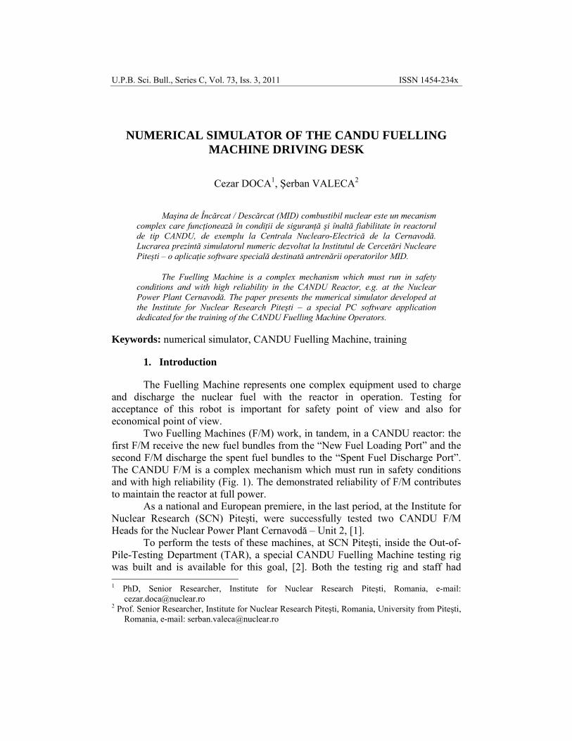
Two Fuelling Machines (F/M) work, in tandem, in a CANDU reactor: the first F/M receive the new fuel bundles from the “New Fuel Loading Port” and the second F/M discharge the spent fuel bundles to the “Spent Fuel Discharge Port”. The CANDU F/M is a complex mechanism which must run in safety conditions and with high reliability (Fig. 1). The demonstrated reliability of F/M contributes to maintain the reactor at full power.
As a national and European premiere, in the last period, at the Institute for Nuclear Research (SCN) Piteşti, were successfully tested two CANDU F/M Heads for the Nuclear Power Plant Cernavodă – Unit 2, [1].
To perform the tests of these machines, at SCN Piteşti, inside the Out-of-Pile-Testing Department (TAR), a special CANDU Fuelling Machine testing rig was built and is available for this goal, [2]. Both the testing rig and staff had 1 PhD, Senior Researcher, Institute for Nuclear Research Piteşti, Romania, e-mail:
[email protected] 2 Prof. Senior Researcher, Institute for Nuclear Research Piteşti, Romania, University from Piteşti,
Romania, e-mail: [email protected]
270 Cezar Doca, Şerban Valeca
successfully assessed by the AECL representatives during two missions. The tests were performed under the control of a Computer System in Automatic Mode.
For the F/M test acceptance, only the normal operator action is permitted, but not any emergency manual intervention. Made under the Quality Assurance Programme’s requirements [9], the tests were supervised and reported as a Romanian success by an AECL team. Let remind here that the Institute for Nuclear Research Piteşti is accredited by Lloyd’s Register for ISO9001-2000.
Fig. 1. CANDU Fuelling Machine
Same, the TAR specialists developed and is operational a numerical
simulator for the CANDU Fuelling Machine Operators’ training, [3]. In recent years, both the testing rig and the numerical simulator were steadily improved to meet the requirements of some foreign potential CANDU NPP owner interested in F/M testing facilities at SCN Piteşti.
2. A short description of the CANDU Fuelling Machine test rig
The design of the CANDU F/M test rig from the Institute for Nuclear Research Piteşti intends to be a replica of the similar equipments operating in a CANDU 6 type NNP. The main equipments are [1]: CANDU Fuelling Machine carriage assembly, PHWR type fuel channels, shield plugs, catenaria, cold and hot loops, oil groups, valve station, connections boards, control desk, computer dedicated to supervise and control the technological processes [5]. The test rig was verified and accepted thru an “electric simulator device” [7] a special tool developed by authors in order to demonstrate the capability of the test rig before coupling the F/M head.
Numerical simulator of the CANDU Fuelling Machine driving desk 271
The endowment from above allows the simulation of various manipulations for refuelling in real reactor’s thermo-hydraulics conditions. All the operations are monitored, correlated and coordinated from a Control Room. That allows controlling all the activities from the CANDU F/M test rig.
3. The Computer Control System
High technical level of the CANDU Fuelling Machine tests required the using of an efficient acquisition and data processing computer control system.
The availability of this system depends on the hardware in use as well as the design of the involved software items.
In any process conditions the system has to provide, [2]: • specific functions to control testing process as: supervising testing
parameters, generating commands, recording data etc.; • ergonomically space distribution for peripherals; • modular design that improves reliability and provides functional
assurances; • system development with minimal hardware and software
modifications.
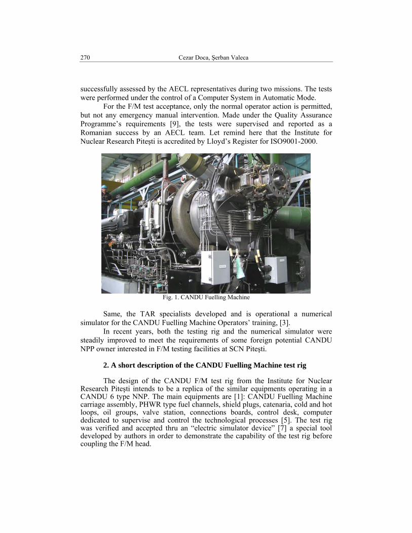
The challenging goal was to build a computer system (hardware and software) designed and engineered to control the test and calibration process of these fuel-handling machines (Fig. 2).
The design takes care both of the functionality required to correctly control the CANDU Fuelling Machine and of the additional functionality required to assist the testing process [6].
We choose modular solutions both for hardware and for software, based on late technologies: VME based hardware systems running OS9/68k (Unix like real-time multi-user multitasking OS), ISaGRAF (process control application oriented development and run-time software), Hawk (cross-compiler and IDE software for C/C++ software development intended to run on other Motorola based hardware), Suretrack (project management software).
The system topology implements open system network concepts that permit communication between different hardware/software platforms (OS9/ Motorola and ix86/ MS-Windows based systems).
272 Cezar Doca, Şerban Valeca
Fig. 2. Partial view of the Computer Control System
4. The Numerical Simulator
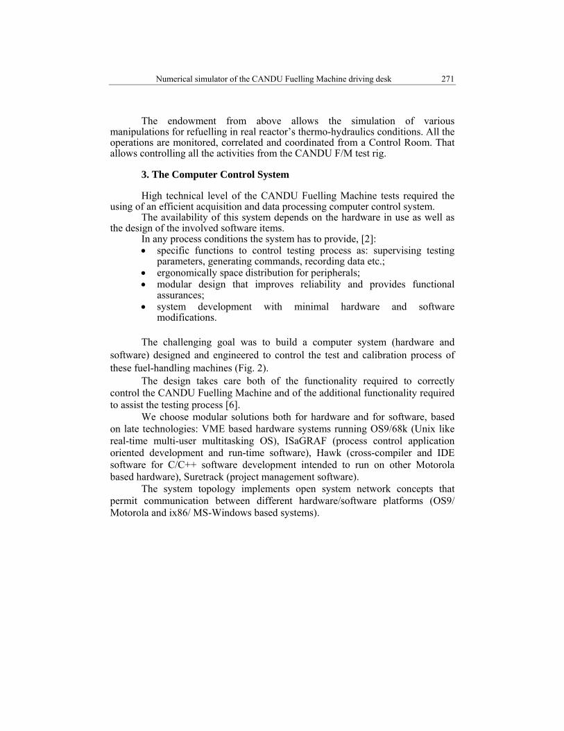
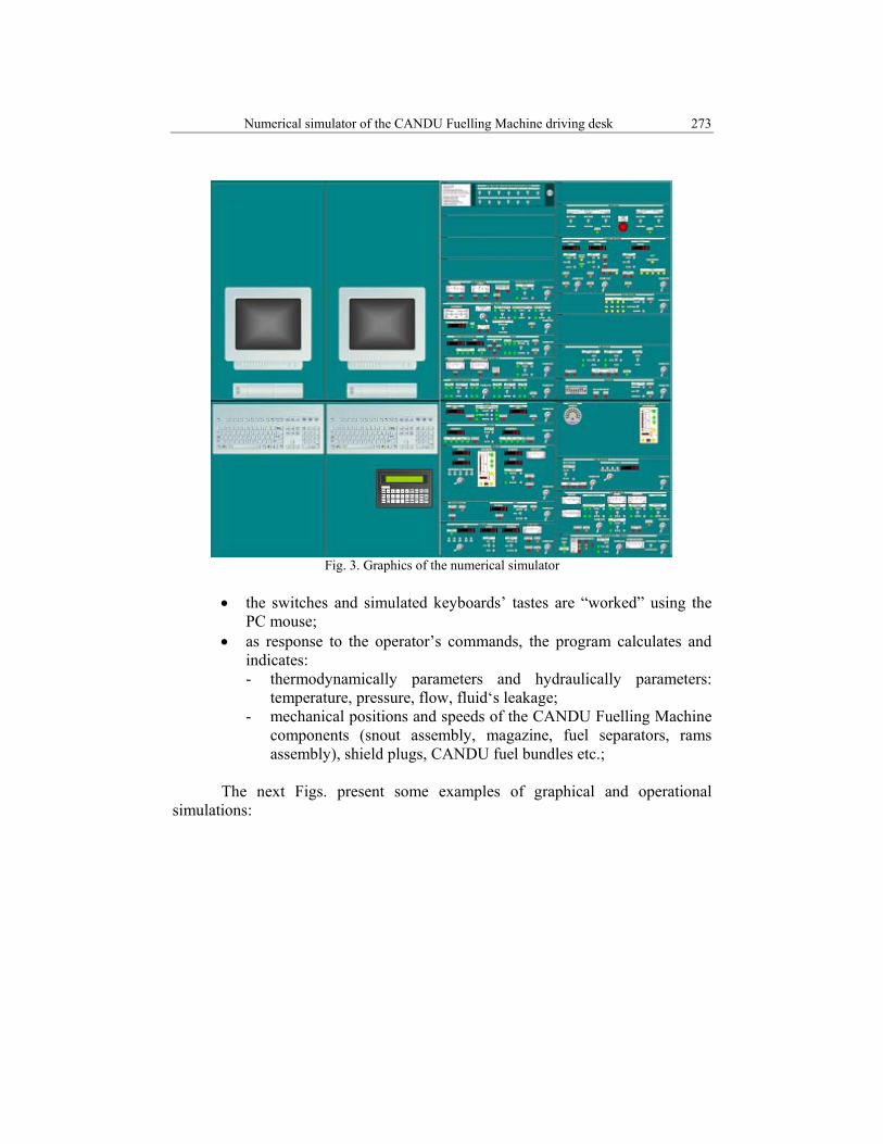
The Numerical Simulator is a special PC program (software application) which simulates the graphics and the functions/operations of the main desk of the Computer Control System (Fig. 3).
The main program’s characteristics are [3]: • it offers a realistic, graphical simulation of the Computer Control
System’s desk at 1:4 scale (compare Fig.s 2 and 3); • it offers a graphical and functional simulation of all objects from the
desk: - 12 linear and nonlinear analogue instruments (ammeters); - 21 digital instruments (voltmeters); - 37 two/three vertical positions switches; - 27 two/three/four/five horizontal positions switches; - 160 white/yellow/orange/red/green colored lamps; - 2 PC Color Displays - 2 PC 101 Windows Keyboards - 1 Handy (special dedicated) Keyboard
Numerical simulator of the CANDU Fuelling Machine driving desk 273
Fig. 3. Graphics of the numerical simulator
• the switches and simulated keyboards’ tastes are “worked” using the
PC mouse; • as response to the operator’s commands, the program calculates and
indicates: - thermodynamically parameters and hydraulically parameters:
temperature, pressure, flow, fluid‘s leakage; - mechanical positions and speeds of the CANDU Fuelling Machine
components (snout assembly, magazine, fuel separators, rams assembly), shield plugs, CANDU fuel bundles etc.;
The next Figs. present some examples of graphical and operational
simulations:
274 Cezar Doca, Şerban Valeca
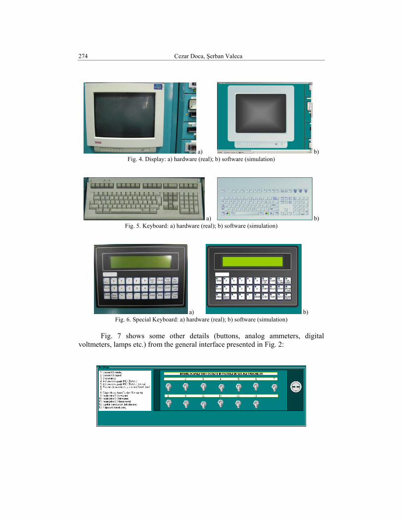
a) b) Fig. 4. Display: a) hardware (real); b) software (simulation)
a) b) Fig. 5. Keyboard: a) hardware (real); b) software (simulation)
a) b) Fig. 6. Special Keyboard: a) hardware (real); b) software (simulation)
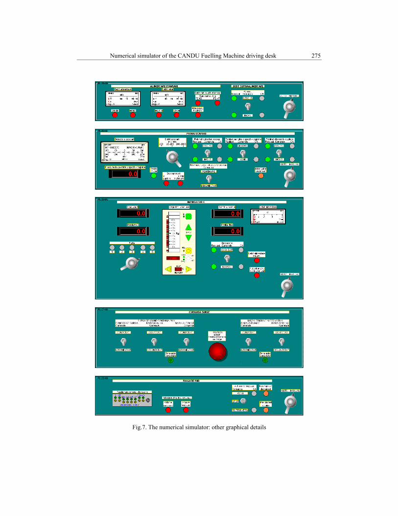
Fig. 7 shows some other details (buttons, analog ammeters, digital voltmeters, lamps etc.) from the general interface presented in Fig. 2:
Numerical simulator of the CANDU Fuelling Machine driving desk 275
Fig.7. The numerical simulator: other graphical details
276 Cezar Doca, Şerban Valeca
The program is dedicated to simulate: • check, setup and calibration for the CANDU Fuelling Machine
components’ instrumentation: - snout clamp; - snout probes; - magazine position; - high pressure drain valve; - B-RAM: position, force, speed and pressure; - Latch-RAM: position, force, speed and pressure; - C-RAM: position, force, speed and pressure; - feelers, retractors and separators fuel stops;
• running the Special JOB R6 in cold and hot conditions.
For an accurately and realistically “response” of the Fuelling Machine and testing rig components at the operator’s commands, the authors developed and implemented in the specialized software application the mathematical models of all physical phenomena which take place, i.e.:
• the time evolutions of the thermodynamically and hydraulically parameters: temperature, pressure, flow, fluid‘s leakage;
• the exactly mechanical positions and speeds of the CANDU Fuelling Machine components: snout clamp; snout probes; magazine position; high pressure drain valve; B-RAM: position, force, speed and pressure; Latch-RAM: position, force, speed and pressure; C-RAM: position, force, speed and pressure; feelers, retractors and separators fuel stops; shield plugs, CANDU fuel bundles etc.;
• the calibration functions for all linear and nonlinear analogue instruments (ammeters) and digital instruments (voltmeters);
• the logical and sequential automation rules for switches and lamps.
The program works with over 2000 variables and constants, well: 103 analogue inputs (AI), 138 digital inputs (DI), 68 digital outputs (DO), 19 flags (FL), 186 set points (SP), 57 technical tolerances, 149 technological constants (CT) etc.
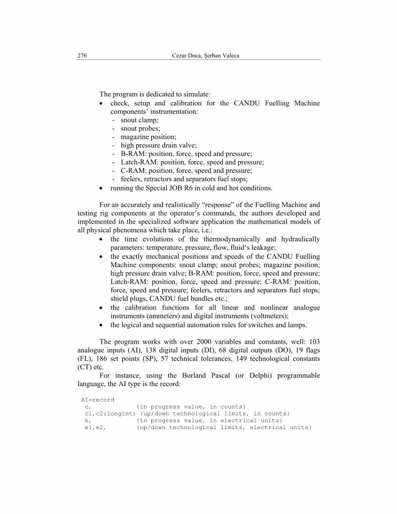
For instance, using the Borland Pascal (or Delphi) programmable language, the AI type is the record: AI=record c, {in progress value, in counts} c1,c2:longint; {up/down technological limits, in counts} e, {in progress value, in electrical units} e1,e2, {up/down technological limits, electrical units}
Numerical simulator of the CANDU Fuelling Machine driving desk 277
i, {in progress value, in engineering units} i1,i2, {up/down technological limits, engineering units} i0v,i5v,i05v, {values used by analogical instruments} d,vc,vi:double;{direction and speeds used in kinematical analyses} end;
Bellow we presented three examples of functions using AI, DI and DO variables, and modelling three water’s flows, [4]:
• for execution elements
( )( )2
2
1i.71AI2i.71AI1c.71AI2c.71AI1i.71AIi.39AIsi.76AIi.75AIi.74AI1c.71AIc.71AI
−−
−++++=
that is: AI71.d:=0; AI71.vc:=0; AI71.c:=AI71.c1+power(AI76.i+AI74.i+AI75.i+AIs39.i-AI71.i1,2)* (AI71.c2-AI71.c1)/power(AI71.i2-AI71.i1,2); AI71.e:=AI71.c*5/65535; AI71.i:=AI71.i1+(AI71.e-AI71.e1)*(AI71.i2-AI71.i1)/ (AI71.e2-AI71.e1);
• for magazine supply
i.81AIi.3452AI69DI29CTs1c.72AIc.72AI −⋅⋅+= that is: AI72.d:=0; AI72.vc:=0; if1:=0; if AI3452.i>=AI81.i then if1:=SQRT(AI3452.i-AI81.i); AI72.c:=AI72.c1+if1*CTs29*DI69; AI72.e:=AI72.c*5/65535; AI72.i:=AI72.i1+(AI72.e-AI72.e1)*(AI72.i2-AI72.i1)/ (AI72.e2-AI72.e1);
• for sealing up
( )( )2
22
2i.77AI1e.77AI2e.77AI3064DO4063DO62DO61DO1e.77AIe.77AI −
⋅+⋅+++=
278 Cezar Doca, Şerban Valeca
that is: AI77.d:=0; AI77.vc:=0; AI77.c:=(AI77.e1+(DO61*power(0,2)+DO62*power(0,2)+DO63* power(40,2)+DO64*power(30,2))*(AI77.e2-AI77.e1)/ power(AI77.i2,2))*65535/5; AI77.e:=AI77.c*5/65535; AI77.i:=AI77.i1+(AI77.e-AI77.e1)*(AI77.i2-AI77.i1)/ (AI77.e2-AI77.e1);
An other example: to accomplish the process of fuel handling (of the new/spent fuel bundles), the F/M Head comprises the following mechanisms, [1]:
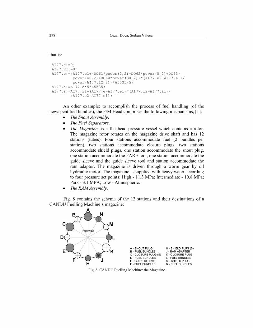
• The Snout Assembly. • The Fuel Separators. • The Magazine: is a flat head pressure vessel which contains a rotor.
The magazine rotor rotates on the magazine drive shaft and has 12 stations (tubes). Four stations accommodate fuel (2 bundles per station), two stations accommodate closure plugs, two stations accommodate shield plugs, one station accommodate the snout plug, one station accommodate the FARE tool, one station accommodate the guide sleeve and the guide sleeve tool and station accommodate the ram adaptor. The magazine is driven through a worm gear by oil hydraulic motor. The magazine is supplied with heavy water according to four pressure set points: High - 11.3 MPa; Intermediate - 10.8 MPa; Park - 3.1 MPA; Low - Atmospheric.
• The RAM Assembly. Fig. 8 contains the schema of the 12 stations and their destinations of a CANDU Fuelling Machine’s magazine:
Fig. 8. CANDU Fuelling Machine: the Magazine
Numerical simulator of the CANDU Fuelling Machine driving desk 279
Bellow we present, as an actual programming example, the logical core for the magazine’s stations analysis (no FARE tool), [5]: case station of 'A':begin {FH = SNOUT PLUG} adapter.z0:=adapter.z0+(-adapter.z0+AI11.i)*adapter.a; adapter.z1:=adapter.z0+adapter.l; if adapter.a=1 then goto a; if (FH.a=0) and (FH.z0-AI7.i>1.52) then FH.c:=0; if abs(FH.z0-AI7.i)<=1.52 then FH.c:=1; if (FH.c=1) and (AI15.i>LLY) then FH.b:=0; if (FH.c=1) and (AI15.i>LLX) then FH.a:=1 else FH.a:=0; if AI7.d>0 then FH.z0:=FH.z0+(-FH.z0+AI7.i)*stopB* FH.c*(1-FH.b); if AI7.d<0 then FH.z0:=FH.z0+(-FH.z0+AI7.i)*stopB*FH.a; FH.z1:=FH.z0+FH.l; if (FH.a=0) and (AI15.i<=LLZ) then FH.b:=1; if (abs(FH.z0-RBY)<=1.52) and (FH.b=1) then HMA:=1; if (abs(FH.z0-RBV)<=1.52) and (FH.b=1) then HMA:=0; a: end; 'B':begin {FCa1, FCa2 = FUEL BUNDLES} FCa1.z0:=FCa1.z0+(FCa1.z0+PBp.z1*PBp.a+PBr.z1*PBr.a+adapter.z1* adapter.a)*stopFC; FCa1.z1:=FCa1.z0+FCa1.l; FCa2.z0:=FCa1.z1; FCa2.z1:=FCa2.z0+FCa2.l; b: end; 'C':begin {ICr = CLOSURE PLUG} adapter.z0:=adapter.z0+(-adapter.z0+AI11.i)*adapter.a; adapter.z1:=adapter.z0+adapter.l; if adapter.a=1 then goto c; if (ICr.a=0) and (ICr.z0-AI7.i>1.52) then ICr.c:=0; if abs(ICr.z0-AI7.i)<=1.52 then ICr.c:=1; if (ICr.c=1) and (AI15.i>LLY) then ICr.b:=0; if (ICr.c=1) and (AI15.i>LLX) then ICr.a:=1 else ICr.a:=0; if AI7.d>0 then ICr.z0:=ICr.z0+(-ICr.z0+AI7.i)*stopB* ICr.c*(1-ICr.b); if AI7.d<0 then ICr.z0:=ICr.z0+(-ICr.z0+AI7.i)*stopB*ICr.a; ICr.z1:=ICr.z0+ICr.l; if (ICr.a=0) and (AI15.i<=LLZ) then ICr.b:=1; if (abs(ICr.z0-RBY)<=1.52) and (ICr.b=1) then HMC:=1; if (abs(ICr.z0-RBX)<=1.52) and (ICr.b=1) then HMC:=0; c: end; 'D':begin {FCa3, FCa4 = FUEL BUNDLES} FCa3.z0:=FCa3.z0+(-FCa3.z0+PBp.z1*PBp.a+PBr.z1*PBr.a+ adapter.z1*adapter.a)*stopFC;
280 Cezar Doca, Şerban Valeca
FCa3.z1:=FCa3.z0+FCa3.l; FCa4.z0:=FCa3.z1; FCa4.z1:=FCa4.z0+FCa4.l; d: end; 'E':begin {GUIDE SLEEVE} adapter.z0:=adapter.z0+(-adapter.z0+AI11.i)*adapter.a; adapter.z1:=adapter.z0+adapter.l; if adapter.a=1 then goto e; if tool.z0-AI7.i>1.52 then tool.c:=0 else tool.c:=1; if (tool.c=1) and (AI15.i>=LLY) then tool.b:=0; if (tool.c=1) and (AI15.i>=LLW) then tool.a:=1; if (guide.a=1) and (AI7.i>=RBE-1.52) and (AI15.i>=LLX) then begin guide.a:=0; guide.b:=1 end; if (tool.a=1) and (guide.a=0) and (abs(AI7.i-RBY)<=1.52) and AI15.i<LLZ) then begin tool.a:=0; tool.b:=1; end; if (guide.a=0) and (AI7.i>=RBE-1.52) and (AI15.i<LLY) then begin guide.b:=0; guide.a:=1 end; if (tool.a=1) and (guide.a=1) and (abs(AI7.i-RBC)<=1.52) and (AI15.i<LLZ) then begin tool.a:=0; tool.b:=1 end; if AI7.d>0 then tool.z0:=tool.z0+(-tool.z0+AI7.i)*tool.c; if AI7.d<0 then tool.z0:=tool.z0+(-tool.z0+AI7.i)*tool.a; tool.z1:=tool.z0+tool.l; guide.z0:=guide.z0+(-guide.z0+tool.z1-202)*guide.a; guide.z1:=guide.z0+guide.l; if (guide.b=1) and (guide.z0>RBE) then HME:=0; if (tool.b=1) and (guide.z0<RBE) then HME:=1; e: end; 'F':begin {NO FARE} f: end; 'H':begin {PBr = SHIELD PLUG} adapter.z0:=adapter.z0+(-adapter.z0+AI11.i)*adapter.a; adapter.z1:=adapter.z0+adapter.l; if adapter.a=1 then goto h; if (PBr.a=0) and (PBr.z0-AI7.i>1.52) then PBr.c:=0; if abs(PBr.z0-AI7.i)<=1.52 then PBr.c:=1; if (PBr.c=1) and (AI15.i>LLY) then PBr.b:=0; if (PBr.c=1) and (AI15.i>LLX) then PBr.a:=1 else PBr.a:=0; if AI7.d>0 then PBr.z0:=PBr.z0+(-PBr.z0+AI7.i)*stopB*PBr.c* (1-PBr.b); if AI7.d<0 then PBr.z0:=PBr.z0+(-PBr.z0+AI7.i)*stopB*PBr.a; PBr.z1:=PBr.z0+PBr.l; if (PBr.a=0) and (AI15.i<=LLZ) then PBr.b:=1; if (abs(PBr.z0-RBY)<=1.52) and (PBr.b=1) then HMH:=1; if (abs(PBr.z0-RBW)<=1.52) and (PBr.b=1) then HMH:=0; h: end; 'J':begin {adapter = RAM ADAPTER}
Numerical simulator of the CANDU Fuelling Machine driving desk 281
if (adapter.a=0) and (AI11.i<RCM-25.4) then adapter.c:=0; if (adapter.a=0) and (AI11.i>=RCM-25.4) then adapter.c:=1; if (adapter.c=1) and (AI15.i<LLX) then adapter.a:=1; if (adapter.c=1) and (AI15.i>=LLX) then adapter.a:=0; adapter.z0:=adapter.z0+(-adapter.z0+AI11.i-RCY)*adapter.a; adapter.z1:=adapter.z0+adapter.l; if (adapter.a=0) and (adapter.z0>=RCM-25.4) then HMJ:=1; if (adapter.a=1) and (adapter.z0<RCM-25.4) then HMJ:=0; j: end; 'K':begin {ICp = CLOSURE PLUG} adapter.z0:=adapter.z0+(-adapter.z0+AI11.i)*adapter.a; adapter.z1:=adapter.z0+adapter.l; if adapter.a=1 then goto k; if (ICp.a=0) and (ICp.z0-AI7.i>1.52) then ICp.c:=0; if abs(ICp.z0-AI7.i)<=1.52 then ICp.c:=1; if (ICp.c=1) and (AI15.i>LLY) then ICp.b:=0; if (ICp.c=1) and (AI15.i>LLX) then ICp.a:=1 else ICp.a:=0; if AI7.d>0 then ICp.z0:=ICp.z0+(-ICp.z0+AI7.i)*stopB* ICp.c*(1-ICp.b); if AI7.d<0 then ICp.z0:=ICp.z0+(-ICp.z0+AI7.i)*stopB*ICp.a; ICp.z1:=ICp.z0+ICp.l; if (ICp.a=0) and (AI15.i<=LLZ) then ICp.b:=1; if (abs(ICp.z0-RBY)<=1.52) and (ICp.b=1) then HMK:=1; if (abs(ICp.z0-RBX)<=1.52) and (ICp.b=1) then HMK:=0; k: end; 'L':begin {FCp1, FCp2 = FUEL BUNDLES} adapter.z0:=adapter.z0+(-adapter.z0+AI11.i)*adapter.a; adapter.z1:=adapter.z0+adapter.l; if FCp1.z0-AI7.i+adapter.l*adapter.a>2*AI7.vi*dt then FCp1.c:=0; if FCp1.z0-AI7.i+adapter.l*adapter.a<=AI7.vi*dt then FCp1.c:=1; if (FCp1.c=1) and (AI7.d>0) then FCp1.z0:=FCp1.z0+(-FCp1.z0+AI7.i+adapter.l*adapter.a)* stopB*FCp1.c; FCp1.z1:=FCp1.z0+FCp1.l; FCp2.z0:=FCp1.z1; FCp2.z1:=FCp2.z0+FCp2.l; l: end; 'M':begin {PBp = SHIELD PLUG} adapter.z0:=adapter.z0+(-adapter.z0+AI11.i)*adapter.a; adapter.z1:=adapter.z0+adapter.l; if adapter.a=1 then goto m; if (PBp.a=0) and (PBp.z0-AI7.i>1.52) then PBp.c:=0; if abs(PBp.z0-AI7.i)<=1.52 then PBp.c:=1; if (PBp.c=1) and (AI15.i>LLY) then PBp.b:=0; if (PBp.c=1) and (AI15.i>LLX) then PBp.a:=1 else PBp.a:=0;
282 Cezar Doca, Şerban Valeca
if AI7.d>0 then PBp.z0:=PBp.z0+(-PBp.z0+AI7.i)*stopB*PBp.c* (1-PBp.b); if AI7.d<0 then PBp.z0:=PBp.z0+(-PBp.z0+AI7.i)*stopB*PBp.a; PBp.z1:=PBp.z0+PBp.l; if (PBp.a=0) and (AI15.i<=LLZ) then PBp.b:=1; if (abs(PBp.z0-RBY)<=1.52) and (PBp.b=1) then HMM:=1; if (abs(PBp.z0-RBW)<=1.52) and (PBp.b=1) then HMM:=0; m: end; 'N':begin {FCp3, FCp4 = FUEL BUNDLES} adapter.z0:=adapter.z0+(-adapter.z0+AI11.i)*adapter.a; adapter.z1:=adapter.z0+adapter.l; if FCp3.z0-AI7.i+adapter.l*adapter.a>2*AI7.vi*dt then FCp3.c:=0; if FCp3.z0-AI7.i+adapter.l*adapter.a<=AI7.vi*dt then FCp3.c:=1; if (FCp3.c=1) and (AI7.d>0) then FCp3.z0:=FCp3.z0+(-FCp3.z0+AI7.i+adapter.l*adapter.a)* stopB*FCp3.c; FCp3.z1:=FCp3.z0+FCp3.l; FCp4.z0:=FCp3.z1; FCp4.z1:=FCp4.z0+FCp4.l; n: end; end;
Shortly, statistically, our numerical simulator uses (in the Delphi programmable language):
• 124 graphical objects of TImage type, • 363 graphical objects of TShape type, • 69 graphical objects of TLabel type, • 114 graphical objects of TSpeedButton type, • 777 procedures, • 205 functions etc.
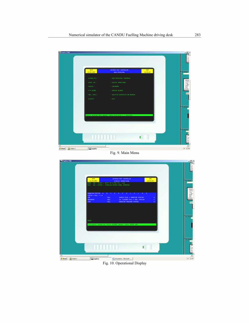
Finally, the next figures present some examples of graphical results
obtained in the CANDU Fuelling Machine testing simulation. More exactly, we have four captures from the PC Display (the PC where our program / application was implemented); the four captures show the simulated display (Fig. 4), and the simulated display presents the on-line (real time) results as effect of the operator’s actions, in these examples on simulated buttons from the simulated “Special Keyboard” (Fig. 6).
Numerical simulator of the CANDU Fuelling Machine driving desk 283
Fig. 9. Main Menu
Fig. 10. Operational Display

284 Cezar Doca, Şerban Valeca
Fig. 11. Calibration Menu
Fig. 12. Alarms Status
Numerical simulator of the CANDU Fuelling Machine driving desk 285
5. Conclusions
During its 39 years of activity, the Institute for Nuclear Research has developed methods, computer codes, and its own experimental infrastructure directed towards the making of end-products, technologies or services with applications in the nuclear power plants area. Involved in the development of nuclear energy, the Institute represents the technical support for the safe and economical operation of nuclear power plants, in accordance with international agreements on the safety of nuclear installations (http://www.nuclear.ro)
The Institute always had and still has as a main task to sustain research and other activities related to the peaceful utilization of nuclear energy. In this meaning, testing the Fuelling Machines at SCN Piteşti is a part of the overall program to assimilate in Romania the CANDU technology.
The main conclusion of this paper, based on the presented results, is that the Institute for Nuclear Research Piteşti, by the Out-of-Pile-Testing Department (but not only), has the facilities, the staff and the experience to perform possible co-operations with any CANDU Reactor owner in the testing, theoretical modelling, simulation and training directions.
The development of Romanian technologies for testing the equipments for charging and discharging the nuclear fuel with the Reactor in operation the acceptance and the verification performed for this job represent a national and European premiere and also represent a component of synergy between nuclear safety and economics.
R E F E R E N C E S
[1]. C. Doca, V. Cojocaru, “Two CANDU-Fuelling Machines Tested at the Institute for Nuclear Reseach Piteşti”, The International Symposium on Nuclear Energy, SIEN 2005, Bucharest, October 21-23, 2005
[2]. C. Doca, C. Păunoiu, “Numerical Simulator for the CANDU Fuelling Machine Operators’ Training”, ECAI 2007 – International Conference – Second Edition: Electronics, Computers and Artificial Intelligence, Piteşti, June 29-30, 2007
[3]. L. Doca, C. Doca, “Ecuaţii fizico-matematice de caracterizare a evoluţiei în timp a parametrilor termohidraulici specifici standului de testare MID”, SCN Piteşti, R.I. nr. 7507/2006 (“Characterization equations for the time evolution of thermo-hydraulic parameters in Fuelling Machine testing rig”, SCN Piteşti Internal Report no. 7507/2006)
[4]. C. Doca, „Simulator numeric pentru pupitrul de comanda al standului MID”, SCN Piteşti, R.I. nr: 6409/2002, 6672/2003, 7005/2004, 7339/2005, 7660/2006, 7762/2007, 7873/2007 (“Numerical Simulator of the CANDU Fuelling Machine Driving Desk“, SCN Piteşti Internal Reports)
[5]. S. Valeca, C. Doca, M. Valeca, “Ciclul de Combustibil Nuclear”, 2008, Editura Universităţii Piteşti- ISBN: 978-973-690-778-4; (Nuclear Fuel Cycle)
[6]. D. Dumitrescu, S. Valeca, N. Marinescu, „Procedură, hard şi soft pentru supravegherea prin calculator a buclei de alimentare a standului MID”- IRNE-RI-2493/1988, Contract 5 TN
286 Cezar Doca, Şerban Valeca
[7]. S. Valeca, C. Iorga, N. Marinescu, Simulator electric cap MID, Brevet nr. 1/3776/09.11.1998 [8]. C. Doca, D. Predescu, S. Dobrescu, O. Maiorescu, Fuel-Handling Machine Tests at the
Institute for Nuclear Research – Piteşti. Computer and Software Research and Engineering, The International Symposium on Nuclear Energy, SIEN 2003, Bucharest, October 24-26, 2003
[9]. S. Valeca, M. Preda, M. Valeca, “Managementul Calitatii Proceselor si Produselor Energo-nucleare”, 2006, Editura Universitatii Pitesti-ISBN (13):978-973-690-583-4.