dimensional optimization for segmented … · dimensional optimization for segmented underpinning...
TRANSCRIPT
BULETINUL INSTITUTULUI POLITEHNIC DIN IAŞI Publicat de
Universitatea Tehnică „Gheorghe Asachi” din Iaşi Volumul 62 (66), Numărul 2, 2016
Secţia CONSTRUCŢII. ARHITECTURĂ
DIMENSIONAL OPTIMIZATION FOR SEGMENTED UNDERPINNING BASED ON THE STRUCTURAL RESPONSE
BY
MARIA SOLONARU*, IRINA LUNGU
and MIHAI BUDESCU
“Gheorghe Asachi” Technical University of Iaşi, Faculty of Civil Engineering and Building Services
Received: June 12, 2016 Accepted for publication: July 15, 2016
Abstract. The comprehension of the structural behavior under static loads
of a building while it is underpinned allows the identification of structural weaknesses and the possibility of optimizing the retrofitting method as well as adopting a fit strategy for the protective measures within the intervention technique. This paper presents an evaluation of the structural effects of the phases within the traditional method of underpinning considered for three different approaches. Three-dimensional linear elastic analyzes for the model geometry consisting of a layered soil profile, a continuous stone foundation and a bearing masonry wall have been performed using finite element software ANSYS. Correlation between normal in-plane stress distribution within the masonry wall and each phase of the underpinning process have been highlighted. Also the effect of the segments dimensions and the numbering process of the segments upon the stress variation within the masonry wall have been analyzed. Optimization of the segments sizes and the numbering of stages can be obtained using the stress assessment of the masonry wall during the underpinning phases, along with the minimising of the risks associated to the technological procedure and ensuring the structural safety.
Keywords: continuous underpinning; ANSYS software; stress assessment; optimization; stress path; masonry wall.
*Corresponding author: e-mail: [email protected]
82 Maria Solonaru, Irina Lungu and Mihai Budescu
1. Introduction
Historic buildings have taken in time some level of damage, the causes
being multiple and complex, from lack of maintenance to the negative effects of the environmental factors and extraordinary events such as changes in the water table level, respectively earthquakes, landslides, heavy traffic and many more. The foundation itself may become a cause for structural damages as unfit in taking over the loads from the structure, for different possible scenarios of decreases in bearing capacity of the soil.
Underpinning is a traditional method utilized to enhance the resistance of the existing foundation. This rehabilitation method may prove to be a necessity when the existing foundation is unfit when additional storey or changes of usage are required, decrease in the values of the soil properties are registered or when excavations for a new building in the vicinity require excavating the soil that supports the existing foundation (Dmochowski et al., 2012; Hammarberg et al., 2009).
The current methods of geotechnical assessment of the existing building infrastructures do not take into account the interaction between the soil, the foundation and the superstructure. Overestimating the damage potential during underpinning works can lead to increased and unnecessary protective measures and underestimating it can lead to partial or overall collapse of the building.
Numerical assessment of the damage potential in the structure can prove concludent in predicting settlement and crack pattern and the assessment accuracy depends on the realistic choice of the soil constitutive models and deformation moduli for the construction materials in correlation with the computational availabilities.
2. Numerical Case Study
Continuous underpinning method is numerically analyzed using finite element package software ANSYS. Traditional concrete underpinning involves extending the existing foundation mainly downward. This rehabilitation as a process is performed in sequential phases with limited segments. The minimum length of an underpinning segment is usually technologically restricted.
The case study examines the variation, the distribution and the path of normal in-plane stresses into a masonry wall within the stages of the underpinning technique. For each case of sequence numbering and dimensions of the underpinning segments, the behavior of the wall is analyzed. Also, analyzes have been made prior to any underpinning intervention for both conditions of the wall, in the initial service state and in the current service state, with lower resistances. The masonry has been modelled in agreement with the
Bul. Inst. Polit. Iaşi, Vol. 62 (66), Nr. 2, 2016 83
macro-modelling hypothesis which considers the structural material as a homogeneous continuum (Cennamo et al., 2009).
2.1. Model Geometry Hypothesis
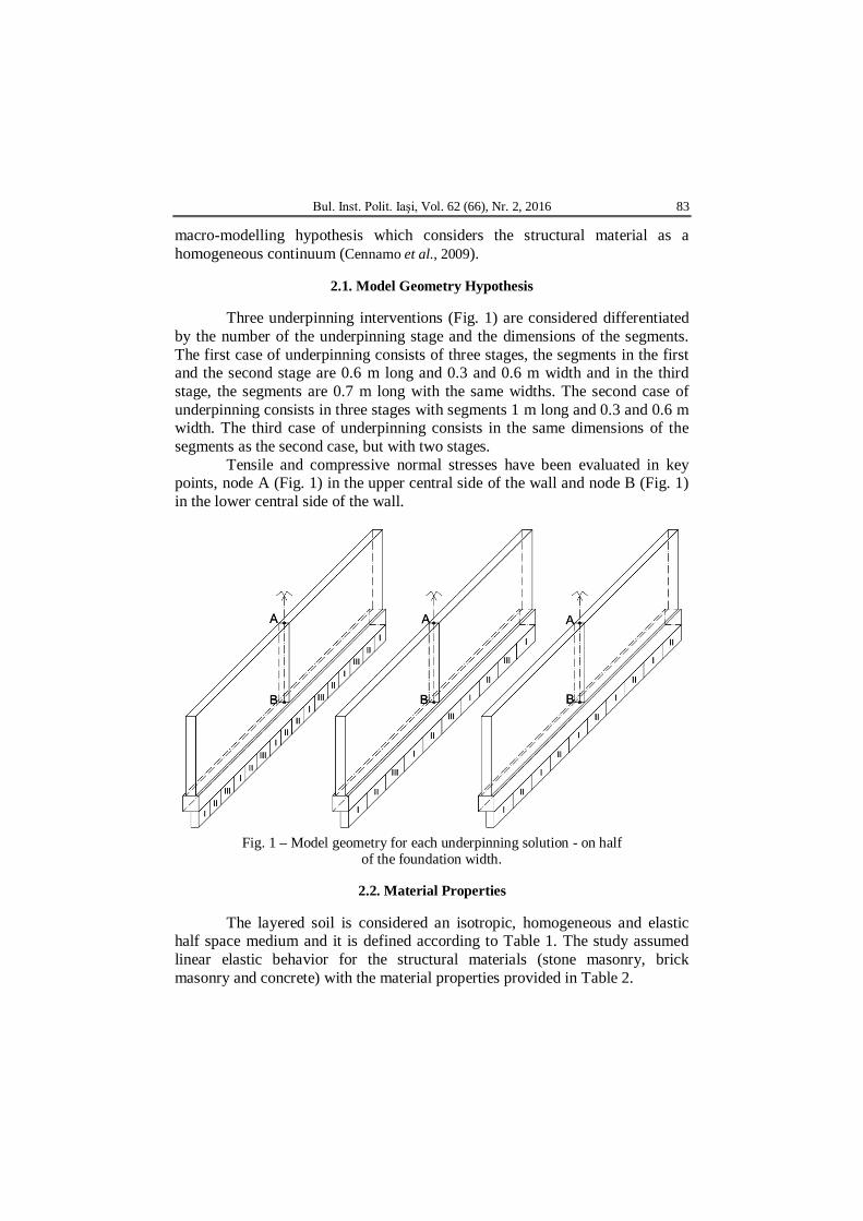
Three underpinning interventions (Fig. 1) are considered differentiated by the number of the underpinning stage and the dimensions of the segments. The first case of underpinning consists of three stages, the segments in the first and the second stage are 0.6 m long and 0.3 and 0.6 m width and in the third stage, the segments are 0.7 m long with the same widths. The second case of underpinning consists in three stages with segments 1 m long and 0.3 and 0.6 m width. The third case of underpinning consists in the same dimensions of the segments as the second case, but with two stages.
Tensile and compressive normal stresses have been evaluated in key points, node A (Fig. 1) in the upper central side of the wall and node B (Fig. 1) in the lower central side of the wall.
Fig. 1 – Model geometry for each underpinning solution - on half
of the foundation width.
2.2. Material Properties
The layered soil is considered an isotropic, homogeneous and elastic half space medium and it is defined according to Table 1. The study assumed linear elastic behavior for the structural materials (stone masonry, brick masonry and concrete) with the material properties provided in Table 2.
84 Maria Solonaru, Irina Lungu and Mihai Budescu
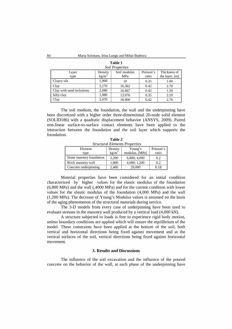
Table 1 Soil Properties
Layer type
Density kg/m3
Soil modulus MPa
Poisson’s ratio
Thickness of the layer, [m]
Clayey silt 1,900 10 0.35 1.00 Clay 2,170 16.362 0.42 2.70 Clay with sand inclusions 2,080 16.667 0.42 1.50 Silty clay 1,980 13.076 0.35 2.10 Clay 2,070 18.000 0.42 2.70
The soil medium, the foundation, the wall and the underpinning have
been discretized with a higher order three-dimensional 20-node solid element (SOLID186) with a quadratic displacement behavior (ANSYS, 2009). Paired non-linear surface-to-surface contact elements have been applied to the interaction between the foundation and the soil layer which supports the foundation.
Table 2 Structural Elements Properties
Element type
Density kg/m3
Young’s modulus, [MPa]
Poisson’s ratio
Stone masonry foundation 2,200 6,800; 4,000 0.2 Brick masonry wall 1,800 4,000; 1,200 0.2 Concrete underpinning 2,400 29,000 0.18
Material properties have been considered for an initial condition
characterized by higher values for the elastic modulus of the foundation (6,800 MPa) and the wall (,4000 MPa) and for the current condition with lower values for the elastic modulus of the foundation (4,000 MPa) and the wall (1,200 MPa). The decrease of Young’s Modulus values is assumed on the basis of the aging phenomenon of the structural materials during service.
The 3-D models from every case of underpinning have been used to evaluate stresses in the masonry wall produced by a vertical load (4,000 kN).
A structure subjected to loads is free to experience rigid body motion, unless boundary conditions are applied which will ensure the equilibrium of the model. These constraints have been applied at the bottom of the soil, both vertical and horizontal directions being fixed against movement and at the vertical surfaces of the soil, vertical directions being fixed against horizontal movement.
3. Results and Discussions
The influence of the soil excavation and the influence of the poured concrete on the behavior of the wall, at each phase of the underpinning have
Bul. Inst. Polit. Iaşi, Vol. 62 (66), Nr. 2, 2016 85
been analyzed. The wall has been analyzed for both group values of the elastic modulus, corresponding to the initial condition of the wall and foundation, as well as to the current condition. The foundation has been underpin on half of its width as well as on its entire width.
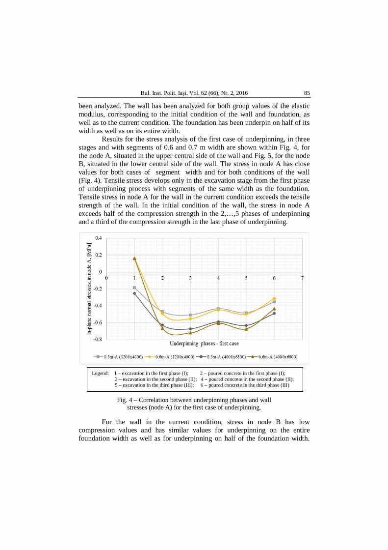
Results for the stress analysis of the first case of underpinning, in three stages and with segments of 0.6 and 0.7 m width are shown within Fig. 4, for the node A, situated in the upper central side of the wall and Fig. 5, for the node B, situated in the lower central side of the wall. The stress in node A has close values for both cases of segment width and for both conditions of the wall (Fig. 4). Tensile stress develops only in the excavation stage from the first phase of underpinning process with segments of the same width as the foundation. Tensile stress in node A for the wall in the current condition exceeds the tensile strength of the wall. In the initial condition of the wall, the stress in node A exceeds half of the compression strength in the 2,…,5 phases of underpinning and a third of the compression strength in the last phase of underpinning.
Fig. 4 – Correlation between underpinning phases and wall stresses (node A) for the first case of underpinning.
For the wall in the current condition, stress in node B has low compression values and has similar values for underpinning on the entire foundation width as well as for underpinning on half of the foundation width.
Legend: 1 – excavation in the first phase (I); 2 – poured concrete in the first phase (I); 3 – excavation in the second phase (II); 4 – poured concrete in the second phase (II); 5 – excavation in the third phase (III); 6 – poured concrete in the third phase (III)
86 Maria Solonaru, Irina Lungu and Mihai Budescu
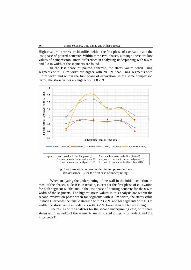
Higher values in stress are identified within the first phase of excavation and the last phase of poured concrete. Within these two phases, although there are low values of compression, stress differences in analyzing underpinning with 0.6 m and 0.3 m width of the segments are found.
In the last phase of poured concrete, the stress values when using segments with 0.6 m width are higher with 28.67% than using segments with 0.3 m width and within the first phase of excavation, in the same comparison terms, the stress values are higher with 68.23%.
Fig. 5 – Correlation between underpinning phases and wall stresses (node B) for the first case of underpinning.
When analyzing the underpinning of the wall in the initial condition, in most of the phases, node B is in tension, except for the first phase of excavation for both segment widths and in the last phase of pouring concrete for the 0.6 m width of the segments. The highest stress values in this analysis are within the second excavation phase when for segments with 0.6 m width, the stress value in node B exceeds the tensile strength with 23.79% and for segments with 0.3 m width, the stress value in node B is with 3.29% lower than the tensile strength.
The results of the analyses for the second underpinning case, with three stages and 1 m width of the segments are illustrated in Fig. 6 for node A and Fig 7 for node B.
Legend: 1 – excavation in the first phase (I); 2 – poured concrete in the first phase (I); 3 – excavation in the second phase (II); 4 – poured concrete in the second phase (II); 5 – excavation in the third phase (III); 6 – poured concrete in the third phase (III)
Bul. Inst. Polit. Iaşi, Vol. 62 (66), Nr. 2, 2016 87
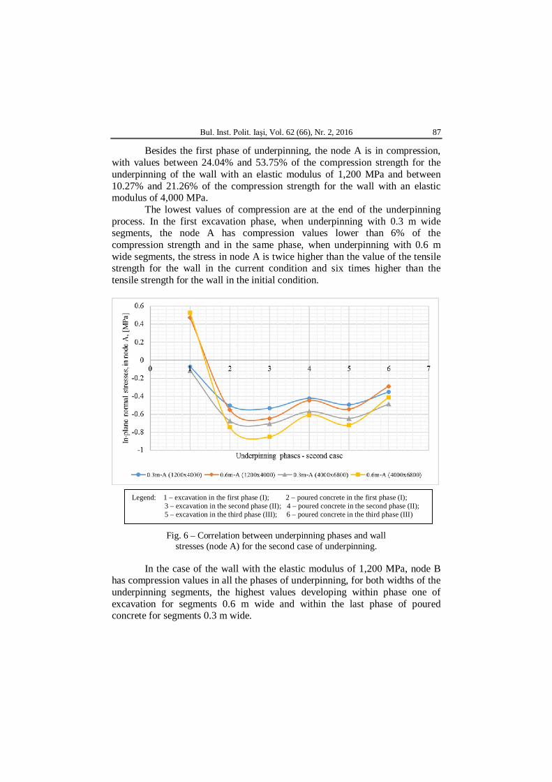
Besides the first phase of underpinning, the node A is in compression, with values between 24.04% and 53.75% of the compression strength for the underpinning of the wall with an elastic modulus of 1,200 MPa and between 10.27% and 21.26% of the compression strength for the wall with an elastic modulus of 4,000 MPa.
The lowest values of compression are at the end of the underpinning process. In the first excavation phase, when underpinning with 0.3 m wide segments, the node A has compression values lower than 6% of the compression strength and in the same phase, when underpinning with 0.6 m wide segments, the stress in node A is twice higher than the value of the tensile strength for the wall in the current condition and six times higher than the tensile strength for the wall in the initial condition.
Fig. 6 – Correlation between underpinning phases and wall stresses (node A) for the second case of underpinning.
In the case of the wall with the elastic modulus of 1,200 MPa, node B has compression values in all the phases of underpinning, for both widths of the underpinning segments, the highest values developing within phase one of excavation for segments 0.6 m wide and within the last phase of poured concrete for segments 0.3 m wide.
Legend: 1 – excavation in the first phase (I); 2 – poured concrete in the first phase (I); 3 – excavation in the second phase (II); 4 – poured concrete in the second phase (II); 5 – excavation in the third phase (III); 6 – poured concrete in the third phase (III)
88 Maria Solonaru, Irina Lungu and Mihai Budescu
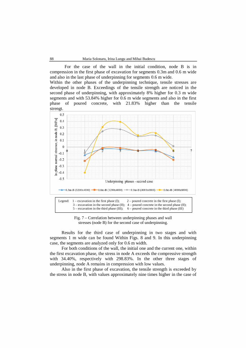
For the case of the wall in the initial condition, node B is in compression in the first phase of excavation for segments 0.3m and 0.6 m wide and also in the last phase of underpinning for segments 0.6 m wide. Within the other phases of the underpinning technique, tensile stresses are developed in node B. Exceedings of the tensile strength are noticed in the second phase of underpinning, with approximately 8% higher for 0.3 m wide segments and with 53.84% higher for 0.6 m wide segments and also in the first phase of poured concrete, with 21.83% higher than the tensile strengt.
Fig. 7 – Correlation between underpinning phases and wall stresses (node B) for the second case of underpinning.
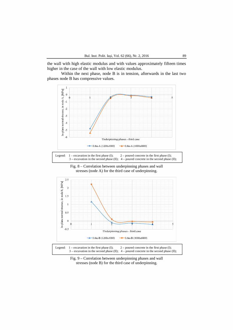
Results for the third case of underpinning in two stages and with segments 1 m wide can be found Within Figs. 8 and 9. In this underpinning case, the segments are analyzed only for 0.6 m width.
For both conditions of the wall, the initial one and the current one, within the first excavation phase, the stress in node A exceeds the compressive strength with 34.40%, respectively with 298.83%. In the other three stages of underpinning, node A remains in compression with low values.
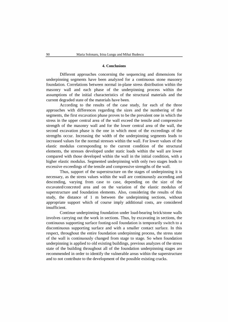
Also in the first phase of excavation, the tensile strength is exceeded by the stress in node B, with values approximately nine times higher in the case of
Legend: 1 – excavation in the first phase (I); 2 – poured concrete in the first phase (I); 3 – excavation in the second phase (II); 4 – poured concrete in the second phase (II); 5 – excavation in the third phase (III); 6 – poured concrete in the third phase (III)
Bul. Inst. Polit. Iaşi, Vol. 62 (66), Nr. 2, 2016 89
the wall with high elastic modulus and with values approximately fifteen times higher in the case of the wall with low elastic modulus.
Within the next phase, node B is in tension, afterwards in the last two phases node B has compressive values.
Fig. 8 – Correlation between underpinning phases and wall stresses (node A) for the third case of underpinning.
Fig. 9 – Correlation between underpinning phases and wall stresses (node B) for the third case of underpinning.
Legend: 1 – excavation in the first phase (I); 2 – poured concrete in the first phase (I); 3 – excavation in the second phase (II); 4 – poured concrete in the second phase (II);
Legend: 1 – excavation in the first phase (I); 2 – poured concrete in the first phase (I); 3 – excavation in the second phase (II); 4 – poured concrete in the second phase (II);
90 Maria Solonaru, Irina Lungu and Mihai Budescu
4. Conclusions
Different approaches concerning the sequencing and dimensions for underpinning segments have been analyzed for a continuous stone masonry foundation. Correlations between normal in-plane stress distribution within the masonry wall and each phase of the underpinning process within the assumptions of the initial characteristics of the structural materials and the current degraded state of the materials have been.
According to the results of the case study, for each of the three approaches with differences regarding the sizes and the numbering of the segments, the first excavation phase proves to be the prevalent one in which the stress in the upper central area of the wall exceed the tensile and compressive strength of the masonry wall and for the lower central area of the wall, the second excavation phase is the one in which most of the exceedings of the strengths occur. Increasing the width of the underpinning segments leads to increased values for the normal stresses within the wall. For lower values of the elastic modulus corresponding to the current condition of the structural elements, the stresses developed under static loads within the wall are lower compared with those developed within the wall in the initial condition, with a higher elastic modulus. Segmented underpinning with only two stages leads to excessive exceedings of the tensile and compressive strengths of the wall.
Thus, support of the superstructure on the stages of underpinning it is necessary, as the stress values within the wall are continuously ascending and descending, varying from case to case, depending on the size of the excavated/concreted area and on the variation of the elastic modulus of superstructure and foundation elements. Also, considering the results of this study, the distance of 1 m between the underpinning sections, without appropriate support which of course imply additional costs, are considered insufficient.
Continue underpinning foundation under load-bearing brick/stone walls involves carrying out the work in sections. Thus, by excavating in sections, the continuous supporting surface footing-soil foundation is temporarily switch to a discontinuous supporting surface and with a smaller contact surface. In this respect, throughout the entire foundation underpinning process, the stress state of the wall is continuously changed from stage to stage. So when foundation underpinning is applied to old existing buildings, previous analyzes of the stress state of the building throughout all of the foundation underpinning stages are recommended in order to identify the vulnerable areas within the superstructure and to not contribute to the development of the possible existing cracks.
Bul. Inst. Polit. Iaşi, Vol. 62 (66), Nr. 2, 2016 91
REFERENCES
Cennamo C., Chiaia B., D’Angelo S., Ferretti D., Seismic Assessment and
Rehabilitation Theatre Based on a Macro-Element Strategy, Proc. of the Internat. Conf. on Protection of Historical Buildings, PROHITECH 09, Rome, Italy, 21-24 June 2009, Vol. 2, 1263-1268.
Cording E.J., Long J.L., Son M., Laefer D.F., Ghahreman B., Assessment of Excavation Induced Building Damage, Proc. of the 2010 Earth Retention Conf., Washington, 2010.
Dmochowski G., Berkowski P., Dudkiewicz J., Adaptation of Early Heritage Masonry Buildings to New Social Assistance Functions, Proc. of the Internat. Conf. on Structural Analysis of Historical Constructions, SAHC 2012, Wroclaw, Poland, 15-17 October 2012, Vol. 3, 2642-2649.
Hammarberg E., Kesner K., Trelstad D., Protection of Historic Urban Structures During Adjacent Construction, Proc. of the Internat. Conf. on Protection of Historical Buildings, PROHITECH 09, Rome, Italy, 21-24 June 2009, Vol. 2, 1393-1398.
Liu G., Houlsby G.T., Augarde C.E., 2-Dimensional Analysis of Settlement Damage to Masonry Buildings Caused by Tunnelling, The Structural Engineer, UK, 79, 1 (2000).
* * * Structural Analysis Guide, ANSYS, Inc., SUA, 2009.
OPTIMIZAREA DIMENSIONALĂ A SEGMENTELOR DE SUBZIDIRE BAZATĂ PE RĂSPUNSUL STRUCTURAL
(Rezumat)
Înţelegerea comportamentului structural al unei clădiri existente aflată sub
încărcări statice, în timp ce este subzidită, permite identificarea deficienţelor structurale şi posibilitatea de optimizare a metodei de reabilitare, precum şi adoptarea unei strategii adecvate privind măsurile de protecţie în cadrul tehnicii de intervenţie. Această lucrare prezintă o evaluare a efectelor structurale ale fazelor metodei tradiţionale de subzidire, considerată pentru trei abordări diferite. Au fost realizate analize liniar elastic, tridimensionale cu ajutorul software-ului cu elemente finite ANSYS, pentru modelul geometric alcătuit dintr-un profil stratificat al terenului de fundare, fundaţie continuă din zidărie de piatră şi un perete portant din zidărie de cărămidă. Au fost evidenţiate corelaţii între distribuţia normală în plan a tensiunilor în peretele de zidărie şi fiecare fază a procesului de subzidire. De asemenea, au fost analizate efectele dimensiunilor segmentelor şi a procesul de numerotare a segmentelor asupra variaţiei tensiunilor în perete de zidărie. Optimizarea dimensiunilor segmentelor şi a numerotării etapelor poate fi obţinută folosind evaluarea tensiunilor peretelui de zidărie în timpul fazelor de subzidire, împreună cu minimizarea riscurilor asociate procedeul tehnologic şi asigurarea siguranţei structurale.
