article magnetic particle inspection optimization solution
TRANSCRIPT
Processes 2021, 9, 1067. https://doi.org/10.3390/pr9061067 www.mdpi.com/journal/processes
Article
Magnetic Particle Inspection Optimization Solution
within the Frame of NDT 4.0
Andreea Ioana Sacarea, Gheorghe Oancea and Luminita Parv *
Department of Manufacturing Engineering, Transilvania University of Brasov, 29 Eroilor Boulevard,
500036 Brasov, Romania; [email protected] (A.I.S.); [email protected] (G.O.)
* Correspondence: [email protected]; Tel.: +40‐740‐851‐396
Abstract: The quality of product and process is one of the most important factors in achieving con‐
structively and then functionally safe products in any industry. Over the years, the concept of In‐
dustry 4.0 has emerged in all the quality processes, such as nondestructive testing (NDT). The most
widely used quality control methods in the industries of mechanical engineering, aerospace, and
civil engineering are nondestructive methods, which are based on inspection by detecting indica‐
tions, without affecting the surface quality of the examined parts. Over time, the focus has been on
research with the fourth generation in nondestructive testing, i.e., NDT 4.0 or Smart NDT, as a main
topic to ensure the efficiency and effectiveness of the methods for a safe detection of all types of
discontinuities. This area of research aims at the efficiency of methods, the elimination of human
errors, digitalization, and optimization from a constructive point of view. In this paper, we pre‐
sented a magnetic particles inspection method and the possible future directions for the develop‐
ment of standard equipment used in the context of this method in accordance with the applicable
physical principles and constraints of the method for cylindrical parts. A possible development di‐
rection was presented in order to streamline the mass production of parts made of ferromagnetic
materials. We described the methods of analysis and the tools used for the development of a mag‐
netic particle inspection method used for cylindrical parts in all types of industry and NDT 4.0; the
aim is to provide new NDT 4.0 directions in optimizing the series production for cylindrical parts
from industry, as given in the conclusion of this article.
Keywords: NDT; magnetic particle inspection; optimization; Industry 4.0
1. Introduction
As digitalization evolves from year to year, many processes or industries are unable
to cope with this progress [1,2]. Technological processes precede the progress of digitali‐
zation, and thus Industry 4.0 was later developed, which also led to the development of
processes such as NDT, where we can now see a lot of digitalization, improvements and
optimizations in terms of Industry 4.0 [2–4]. Despite this, the development of Industry 4.0
comes with changes in terms of the user–equipment interface, and any change involves
the unknown, which can bring about reluctance or lack of confidence in the user in the
displayed result. Digitalization comes primarily with the improvement and development
of new processes and methods, but it also comes with the disposal of human errors, espe‐
cially in the field of NDT methods where the final interpretation and final decision in‐
volves the human factor [5–7]. NDT, which stands for the term “nondestructive testing”,
does not affect the surface quality of the parts, the material, or the geometry of the tested
components; this term is found in various publications, books, and media, and it is known
as NDT, NDI, or NDE using different endings (e.g., testing, inspections, examinations,
evaluations). The abbreviation used in this manuscript is NDT and includes all inspection
processes by nondestructive methods. From Industry 4.0, which involves smart, digitized,
Citation: Sacarea, A.I.; Oancea, G.;
Parv, L. Magnetic Particle Inspection
Optimization Solution within the
Frame of NDT 4.0. Processes 2021, 9,
1067. https://doi.org/10.3390/pr
9061067
Academic Editor: Sergey Y. Yurish
Received: 31 May 2021
Accepted: 16 June 2021
Published: 18 June 2021
Publisher’s Note: MDPI stays neu‐
tral with regard to jurisdictional
claims in published maps and institu‐
tional affiliations.
Copyright: © 2021 by the authors.
Licensee MDPI, Basel, Switzerland.
This article is an open access article
distributed under the terms and con‐
ditions of the Creative Commons At‐
tribution (CC BY) license (https://cre‐
ativecommons.org/licenses/by/4.0/).
Processes 2021, 9, 1067 2 of 18
and optimized nondestructive inspection processes, the development of the NDT 4.0 in‐
dustry is currently facing challenges such as infrastructure limitations, lack of presence of
sensors for transmitting measured values, recorded parameters, etc. The development of
NDT 4.0 involves firstly ensuring the direct connectivity of the devices to displays in the
laboratories, to analyzing the parameters or data in real time. It is an advantage to develop
DAS (data acquisition system) systems by taking values and signals and processing them
at a PC through connection cables and private intranet platforms or even wireless connec‐
tions.
A shortcoming of these NDT methods for Industry 4.0 development and digitaliza‐
tion is the recent development of new equipment and new design proposals [1,8–10]. One
of the main challenges of this industry is, first of all, to digitize and make smart connec‐
tions between already used equipment/installations and PCs for displaying and pro‐
cessing the data recorded through sensors or connection cables, or more precisely, to form
DAS systems. If the installations are old and do not have Internet options or other smart
applications, then it is necessary to firstly implement electronics and “host” computers for
these DAS connections. Along with their implementation, it is necessary to develop IT
applications to ensure cooperative infrastructures and also intelligible and intuitive inter‐
faces, but they also need to have the role of supporting security and limiting access. Both
Industry 4.0 and the transition and approach to the concept of NDT 4.0 are sensory areas
based on data acquisition and processing.
The main purpose of the NDT 4.0 approach and development is to have real‐time
access to all the obtained results and the used parameters [11,12]. Many papers have been
published on the development of the NDT industry, addressing its concepts in terms of
the design, production, maintenance, lifespan, examinations, etc. [11–15]. In this manu‐
script, we adopt an approach to the NDT 4.0 concept that involves optimizing inspection
parameters and eliminating the human factor. Specifically, this paper addresses the con‐
cept of NDT 4.0 by optimizing and developing the magnetic particle inspection method
for cylindrical parts, which we discuss later.
Industry 4.0 and NDT have undergone several stages of revolutions, starting from
NDT 1.0. As the earliest generation, NDT 1.0 appeared with the development of the In‐
dustry 1.0 concept through the need to monitor and ensure safety by performing periodic
checks through a prescribed and probable process, using tools that are not complex in
order to increase human capacity. Examples of such developments are tactile devices, im‐
proved visual inspection through magnifying glasses, and other auxiliary devices. NDT
2.0 represents the second stage of process development, represented by the use of electric‐
ity and the use of analog devices by using waves or frequencies outside the sensory do‐
main perceived by the human body. During this stage, NDT methods such as ultrasound,
eddy currents, X‐rays, fluorescent penetration substances in the PT method, and fluores‐
cent particles for the MT method were developed, as well as techniques developed for
visual examination and inspection by developing devices such as cameras. NDT 3.0,
which represents the third stage of development in industry, includes the development in
terms of digital technology, through the acquisition, storage, and processing of data from
inspection processes, the development of displays, and the reproduction of 2D and 3D
defects; its aim is to provide an efficient, safe, and faster interpretation of the obtained
results. There have been developments in the inspection chambers for methods using
probes and also sensors such as ET, UT, thermography, visual inspections, X‐rays, and
even industrial tomography.
NDT 4.0 represents the latest generation of the development of this industry and in‐
cludes the combination of generation 3.0 and generation 2.0 by eliminating human errors
and improving inspection systems and the continuous development of digital technolo‐
gies and physical methods used, with this development being achieved independently or
even simultaneously. It aims at an improvement and optimization in this generation of
both repair processes and overhauls and the maintenance throughout the life of the equip‐
ment. Another need for the development of the NDT 4.0 industry is the cause of depletion
Processes 2021, 9, 1067 3 of 18
of natural resources and environmental pollution; here, we refer to the sustainable devel‐
opment of NDT processes that develops digitalization while also eliminating human error
[1–4]. Sustainability is the field that in recent year has attracted the most attention in pro‐
duction research from various industries and is an important factor not only in technolog‐
ical development but also in the innovation of sustainable systems. The role of production
in sustainability is important because in many processes, methods are consuming natural
resources or resources that affect the quality of the environment and the health of human
factors. The biggest confrontation in the world is to face a land with finite resources and
limited natural resources.
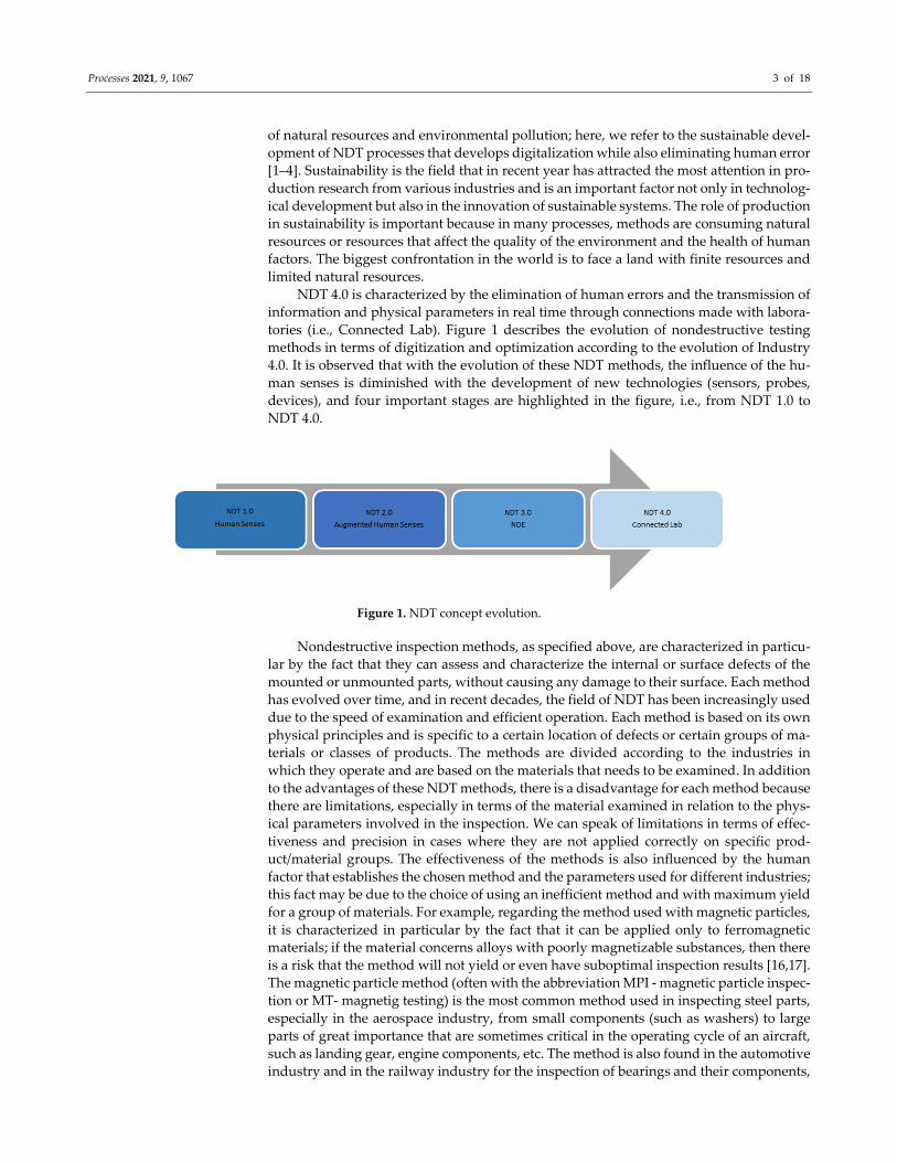
NDT 4.0 is characterized by the elimination of human errors and the transmission of
information and physical parameters in real time through connections made with labora‐
tories (i.e., Connected Lab). Figure 1 describes the evolution of nondestructive testing
methods in terms of digitization and optimization according to the evolution of Industry
4.0. It is observed that with the evolution of these NDT methods, the influence of the hu‐
man senses is diminished with the development of new technologies (sensors, probes,
devices), and four important stages are highlighted in the figure, i.e., from NDT 1.0 to
NDT 4.0.
Figure 1. NDT concept evolution.
Nondestructive inspection methods, as specified above, are characterized in particu‐
lar by the fact that they can assess and characterize the internal or surface defects of the
mounted or unmounted parts, without causing any damage to their surface. Each method
has evolved over time, and in recent decades, the field of NDT has been increasingly used
due to the speed of examination and efficient operation. Each method is based on its own
physical principles and is specific to a certain location of defects or certain groups of ma‐
terials or classes of products. The methods are divided according to the industries in
which they operate and are based on the materials that needs to be examined. In addition
to the advantages of these NDT methods, there is a disadvantage for each method because
there are limitations, especially in terms of the material examined in relation to the phys‐
ical parameters involved in the inspection. We can speak of limitations in terms of effec‐
tiveness and precision in cases where they are not applied correctly on specific prod‐
uct/material groups. The effectiveness of the methods is also influenced by the human
factor that establishes the chosen method and the parameters used for different industries;
this fact may be due to the choice of using an inefficient method and with maximum yield
for a group of materials. For example, regarding the method used with magnetic particles,
it is characterized in particular by the fact that it can be applied only to ferromagnetic
materials; if the material concerns alloys with poorly magnetizable substances, then there
is a risk that the method will not yield or even have suboptimal inspection results [16,17].
The magnetic particle method (often with the abbreviation MPI ‐ magnetic particle inspec‐
tion or MT‐ magnetig testing) is the most common method used in inspecting steel parts,
especially in the aerospace industry, from small components (such as washers) to large
parts of great importance that are sometimes critical in the operating cycle of an aircraft,
such as landing gear, engine components, etc. The method is also found in the automotive
industry and in the railway industry for the inspection of bearings and their components,
Processes 2021, 9, 1067 4 of 18
often made of special steels, and also in the civil engineering industry to characterize
cracks in cement concrete specimens [18–23]. Although it seems easy to understand and
apply, the method is complex and is based on many theories such as the effects of metal‐
lurgical materials, fluid movement dynamics, human factors and electromagnetic theo‐
ries—with all these factors integrated into one method and one applicability.
In this manuscript, the magnetic particle method is approached together with the
analysis of the physical parameters used for the cylindrical parts and their optimization
by developing an auxiliary device that reduces the inspection time and eliminate human
errors, as well as ensure an ergonomic position of the inspector during the execution of
the method while using standard control equipment. There are very few studies and aux‐
iliary tools that ensure a correct determination of the tests and parameters used, and there‐
fore in this manuscript, we address this concern to ensure a uniform magnetic field of the
cylindrical parts subjected to examination.
The values established for the electric current intensity have an importance in ensur‐
ing an optimal magnetic field that can highlight the existing discontinuities on the surface
of the parts, and so attention is given to the values of the tangential magnetic field and the
remaining magnetism in the part. The biggest risk in the wrong choice of parameters is to
not highlight the discontinuities or to mark them with false indications, which has a high
risk factor for any type of examined part. The magnetic field is a property with high sen‐
sitivity in any field, and it has unique properties in terms of impact on components/tech‐
nologies. Magnetic phenomena are very important in any field of science, and the remain‐
ing magnetism has become an area of interest, as it is a critical characteristic in certain
functional ensembles. The magnetic particle method is the method most often used to de‐
tect microdefects (usually linear cracks) in the case of materials with ferromagnetic prop‐
erties. The principle of examination with this method is quite simple, namely that for the
cylindrical parts, standard control equipment is used, with a central conductor mounted,
through which electric current passes [5,7]. The parts are magnetized, and then the ap‐
plied magnetic particles are attracted to the defective areas; however, it is important that
the orientation of the defects is about 90 degrees from the direction of the field lines, as
this is one of its basic characteristic methods [24–26]. The smaller the angle, the lower the
sensitivity and efficiency of the method, and the lower the probability of detecting defects.
A main advantage of this method—which is agreed by many industries, especially the car
and aircraft manufacturers—is that as long as the method is applied correctly and the
chosen parameters are optimal, there is a probability that defects are detected from the
beginning.
In this manuscript, we aim to optimize the MT method with a central conductor by
developing a device that ensures a uniform magnetic field on the surface of cylindrical
parts, thereby ensuring constant parameters during the process and the same probability
of detecting defects on the entire surface. The design of the device is chosen first, with the
help of a multicriteria analysis, taking into account both the examination conditions and
working environments used and also the design conditions for manufacturing and the
physical parameters to be obtained. In the current control stage, the parts are positioned
directly on the central conductor, and they are in direct contact with it, which implies a
nonuniform magnetization on the surface of the part, i.e., a nonuniform magnetic field
with values gradually decreasing from the contact area with the mandrel piece to the op‐
posite surface of the part, where it is no longer in contact with the mandrel. The value of
the magnetic field is one of the most important features of this inspection process because
if the CM value is too low, there is a risk that fine or even large defects are not highlighted,
and if the CM value is too high, each imprint can be highlighted, which leads to a difficult
interpretation from a visual point of view.
2. Materials and Methods
The materials and methods used in this manuscript are known methods in research,
i.e., data acquisition systems and manufacturing design; these are applied here for the
Processes 2021, 9, 1067 5 of 18
development of a new device to help with the improvement and optimization of the mag‐
netic particle method. Data acquisition systems are used for measuring and recording
physical parameters, and manufacturing design is used not only for the correct choice of
device design and thinking, but also for the constraint and importance of physical param‐
eters, as well as the effective design of the constructive solution, chosen in the shadow of
an applied multicriteria analysis.
The data acquisition system (DAS) in this work measures the values of physical pa‐
rameters used in magnetic particle inspection. The data acquisition system here consists
of a current generating source, Hall probes for measuring magnetic field values, and a
digital screen that allows for recording and displaying measured values. Hall probes are
based on the effect of the same name and are used mainly to measure a tangential mag‐
netic field or the remaining magnetic field values. Hall effect sensors are characterized by
the measuring range as well as the working environment temperatures. In the case of the
magnetic particle method, the working temperature is controlled, most often the equip‐
ment placed in industrial halls with a controlled temperature or in testing laboratories.
With the help of a data acquisition system consisting of a generating source and devices
for measuring the magnetic field, provided with Hall sensors, tangential magnetic field
values can be recorded.
The manufacturing design in this work looks at designing a device that aims to opti‐
mize the NDT inspection process with magnetic particles for cylindrical parts. To do this,
the design conditions were taken into account so that its realization process can be easily
implemented [1,3]. It is used conceptually to design the parts in pairs, trying as much as
possible to use the same types of parts, both in one part of the device and in the other.
Choosing the design of parts with simple configuration and sections helps to facilitate
costs, time, and manufacturing processes, especially if users opt for additive manufactur‐
ing by the 3D realization of certain components of the device. In our work, these were
used as main elements in the construction of the proposed model; the parts consisted of
two cylindrical drums, moving arms, the sole of the device, all with sections with simple
geometries. A second condition that was taken into account in the design of the variant
proposed for the device is that of the use of symmetrical parts. One of the important char‐
acteristics of the symmetrical parts is their fast and correct assembly, as no sensors or other
auxiliary devices are needed in order to orient them. It is important that the device has as
few constructive elements and with geometries as simple as possible and can be disas‐
sembled, in order to ensure safe transport, easy packaging conditions, and a quick and
correct assembly.
Assembly must be done as easily as possible, both manually and automatically—it is
much easier to program assembly robots with simple and short movements than large
and complex movements. We opted for a device that has few main constructive elements
that require assembly, such as: support/seating soles, fixing, moving arms, drums for ro‐
tating parts and height actuation device. We took into account our desire to have a device
with a utility for a wider range of cylindrical products with different diameters, and thus
it was intended that the disassembly/assembly of the two drive drums be performed as
simple and fast as possible. Depending on the diameters of the examined parts, the two
provided drums must be interchangeable so as to ensure the coaxiality of the central con‐
ductor and the part. Both the drums and the support soles and movable arms were de‐
signed symmetrically, and their symmetry is considered the sign of quality assurance,
following the manufacturing process of the device. From the point of view of additive
manufacturing, the configuration of symmetrical parts is easier to achieve; moreover, a
symmetrical part is easier to assemble with another part that is also symmetrical, so there
is no risk of confusing the positions or directions of placement or assembly.
Regarding the design concept, the proposed device model resembles a jack, possibly
with a hydraulic drive. We approached the design from a classic configuration of the hy‐
draulic table assembly, where the upper part is arranged with two drums (made of soft
material without degrading the surface of the part during rotation) to ensure a constant
Processes 2021, 9, 1067 6 of 18
rotation with a controlled speed of the part. With the rotation of the cylindrical part, the
risk of false indications or the risk of deleting the relevant indications is also eliminated.
Without the presence of an auxiliary device, the parts are handled manually during the
examination. The device is made of the following component parts (see Figure 2):
Supporting legs/movable arms that ensure sufficient height;
Interchangeable drums for parts with different diameters made of soft material such
as plastic, silicone, or silicone‐coated plastic;
A support sole, provided with supports to facilitate its transfer from one piece of
equipment to another.
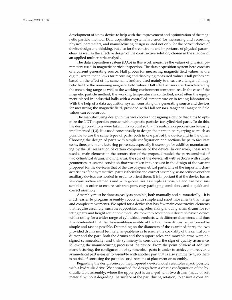
Figure 2 shows the design proposal for such a device, provided in the tank of a stand‐
ard equipment for examination with magnetic particle inspection. In accordance with the
manufacturing design as described above, it is very important that the device can be easily
assembled and has a configuration with simple geometry and that we use symmetrical
parts. The proposed design has a simple configuration; it does not fill the volume of the
tank, and it provides the necessary space for handling parts. In addition, it has a very
small footprint at the base of the basin and is sealed so that magnetic particles does not
remain accumulated on the inner surfaces of the device. The access to the part to be exam‐
ined is not affected, but the possibility of inspection the parts is facilitated, given that the
parts are closer to the visual field of the operator.
Figure 2. Main view of the device and the optimal position of the part in which the coaxiality is
ensured.
In order to build the device, we took into account that this method generates a mag‐
netic field, and that the materials chosen in its construction must not be ferromagnetic,
especially in the area near the central conductor/magnetic poles. If the supporting ele‐
ments of the parts are ferromagnetic, they will be magnetized, and in turn they can mag‐
netize the already demagnetized parts following the control. With the realization of this
new type of device, we propose an optimization of the inspection process from the point
of view of ensuring the constant working parameters, as well as from the point of view of
the working time of the entire inspection process.
Regarding the physical principles and relationships, it can be seen that this NDT
method—like any other method in this category—is based on physical methods and prin‐
ciples, as well as constraints in this regard; therefore, one of the most important constraints
is that the parts must be made of ferromagnetic material, and the ideal inspection case is
to ensure a uniform magnetic field on all surfaces of the parts subject to inspection [24,25].
A common problem in this type of inspection is the remaining magnetism left in the part,
Processes 2021, 9, 1067 7 of 18
which can affect other parts during operation in the assembly of which it is part; this is a
critical feature even for human safety if it is part of an engine assembly from an aircraft
for example, or other areas with high sensitivity in use [20,26,27]. The ideal case of physi‐
cal parameters implies a constant value of the magnetic field, which also means a uniform
control and a similar highlighting for all inspection areas. Thus, the ideal case is to mag‐
netize simultaneously both the upper part and the lower part, without the need for a 180
degrees rotation (in the case of supporting the part on the central conductor) of the part
to ensure a magnetic field also on the lower surface.
The value of the magnetic field usually decreases in proportion to the distance from
the mandrel of the part; the role of the mandrel in this type of assembly is to ensure the
passage of electric current in order to highlight the discontinuities, both at the inner sur‐
face of the part and its outer surface. There is a linear decrease with the increase of the
distance between the central conductor and the part to be examined.
One of the most important physical characteristics is represented by the magnetic
field and the assurance that it is evenly distributed on the surface of the parts. The ap‐
proximate values must be between 30 and 60 A/cm, as this is an interval with values that
guarantee the highlighting of possible indications (such as cracks). If the values are lower
than this interval, then there is the possibility that the defects are not highlighted, meaning
that the part is not magnetized enough. If the values are too high, then the magnetism of
the part is too high, and the particles of either part becomes attracted even in the indica‐
tions of fine scratches. Thus, we can talk about irrelevant indications, which make it diffi‐
cult to examine the surfaces.
Another important feature is the choice of the type of magnetization, depending on
the orientation of the defects to be highlighted; there are two types of magnetization, the
circumferential tangential magnetization and the longitudinal tangential magnetization.
The importance of this characteristic is given by one of the constraints of the method—the
orientation of the defects must always be perpendicular to the direction of the magnetic
field lines.
Demagnetization of parts after inspection is also an important factor to consider in
this method because it is important that the parts are to be demagnetized evenly on their
entire surface so that there are no high values of magnetism remaining in the part. It is
preferable for the values of the magnetism after inspection to be close to zero because a
possible magnetism on or in the part can affect the functional state of the system of which
it is a part, or even the part of other neighboring components.
The multicriteria analysis method was chosen in this manuscript in order for us to
choose the optimal variant from a constructive point of view, not only of the device to
ensure the optimization of physical parameters but also of inspection. Within the mul‐
ticriteria analysis, several criteria were determined from a constructive point of view,
namely the criteria of the materials used, the chosen components, and the characteristics
they must meet. It is very important that the multicriteria analysis is performed in relation
to the chosen criteria.
Case Study
In order to carry out a case study highlighting the importance of ensuring constant
physical parameters, we used an example of a cylindrical piece with a diameter of approx‐
imately 100 mm, positioned on a central conductor with a diameter of 55 mm. It is consid‐
ered the ideal case in ensuring a magnetization in both directions, having a magnetic field
between 30 and 60 A/cm on the entire surface of the part, as well as in ensuring that at the
area of contact with the central conductor, the magnetic field is at the limit (higher than
30 A/cm) and that in the lower part (180° to central conductor), it is below the minimum
required value.
The way of obtaining the parameters consisted of the effective application of the in‐
spection method on standard equipment. Thus, the part was positioned on the central
Processes 2021, 9, 1067 8 of 18
conductor, where a magnetization cycle of at least 5 s is ensured, and then the tangential
magnetic field in both directions—longitudinal and circular, respectively—was checked
in turn. The current values were entered depending on the performance of the equipment
used, so as to ensure the optimal tangential magnetic fields in order to ensure the detection
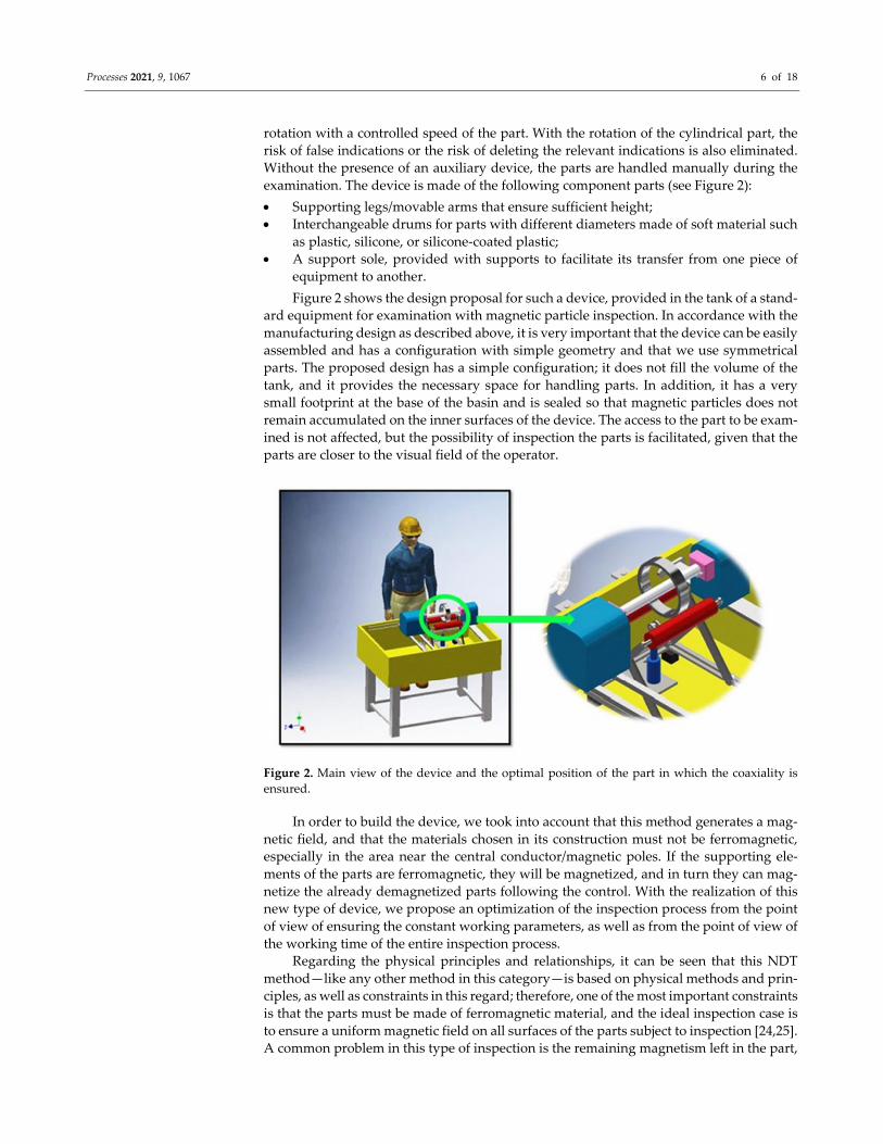
of possible relevant indications. After establishing the magnetization parameters, a device
was used to measure the magnetic field, and its display should show the magnetic field
value on different areas of the part, starting from the contact area of the central conductor
and the part to the lower end of the part (Figure 3).
Figure 3. Hall probe positioning for magnetic field measurement.
Figure 3 illustrates the orientations of detectable discontinuities according to the ori‐
entation of the magnetic field lines. On the left side of the image, the field lines are longi‐
tudinal, in the horizontal direction, which implies the possibility of detecting discontinu‐
ities perpendicular to them. The indication is highlighted on the part in the vertical direc‐
tion, with a black line. For the circular tangential magnetic field, it is the opposite case, in
which the field lines have a vertical direction, and the discontinuity is oriented horizon‐
tally, perpendicular to the direction of the field lines. Because the detection of defects is
characterized by the direction of the field lines, most of the times we chose to use the
equipment capable of using a combined magnetization in both directions, in order to
achieve a short inspection time and an efficient examination. For a longitudinal tangential
magnetic field, it is possible to detect circumferential defects (the left side), and for a cir‐
cular tangential magnetic field, it is possible to detect longitudinal defects (the right side).
After ensuring the optimal parameters, the part was magnetized in both directions simul‐
taneously, having a combined magnetization, followed by a demagnetization with the
same values of current intensity. Demagnetization was followed by measuring the re‐
maining magnetism on the entire surface of the part.
The case study was performed on standard control equipment, where the part is in
contact with the central conductor (current control situation). For example, one cylindrical
part made of ferromagnetic material (stainless steel) with an outer diameter equal to 100
mm was chosen as a reference. The part was positioned on the central conductor; the
physical parameters were chosen such that the tangential magnetic field on the surface of
the part was between 30 and 60 A/cm. The magnetization time was also chosen, and the
demagnetization of the parts was activated. The total magnetization time of the part in
both directions was at least 5 s, and the demagnetization was performed with the same
amperage values as those used for magnetization. For example, for a part with the outer
diameter equal to 100 mm and a central conductor with a 55 mm diameter, the optimal
amperage values are 1.5 kA (circular direction) and 5.5 kAT (longitudinal direction).
Processes 2021, 9, 1067 9 of 18
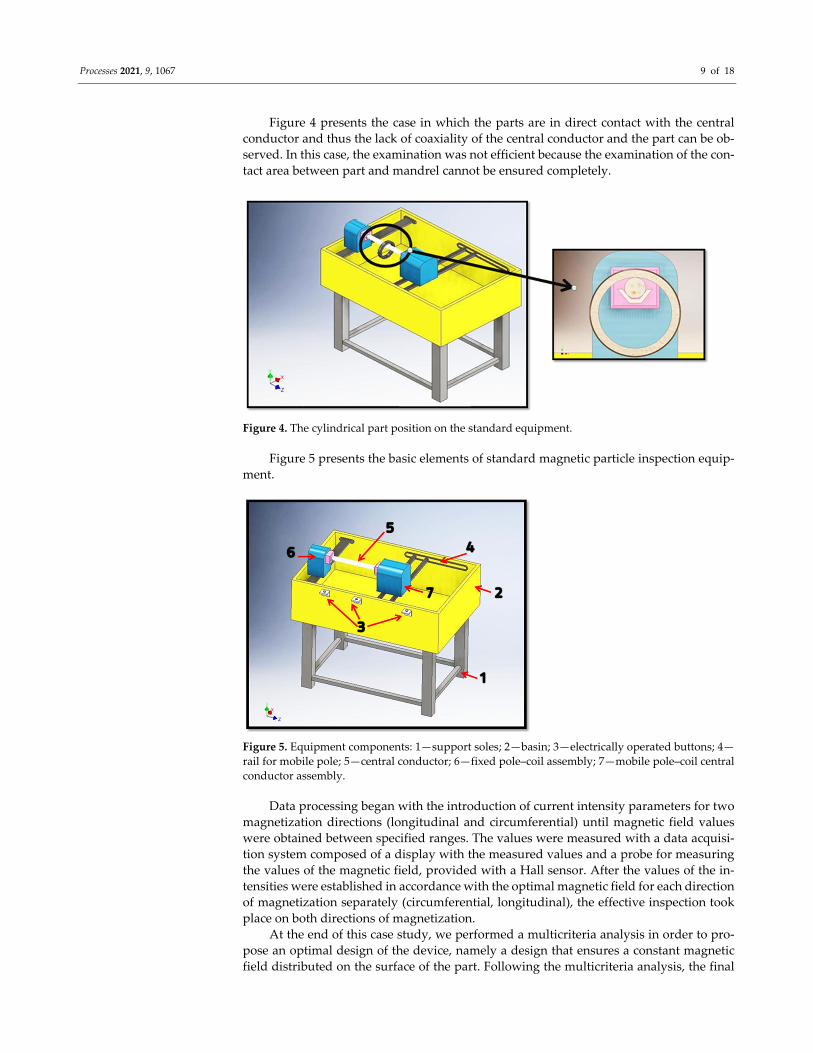
Figure 4 presents the case in which the parts are in direct contact with the central
conductor and thus the lack of coaxiality of the central conductor and the part can be ob‐
served. In this case, the examination was not efficient because the examination of the con‐
tact area between part and mandrel cannot be ensured completely.
Figure 4. The cylindrical part position on the standard equipment.
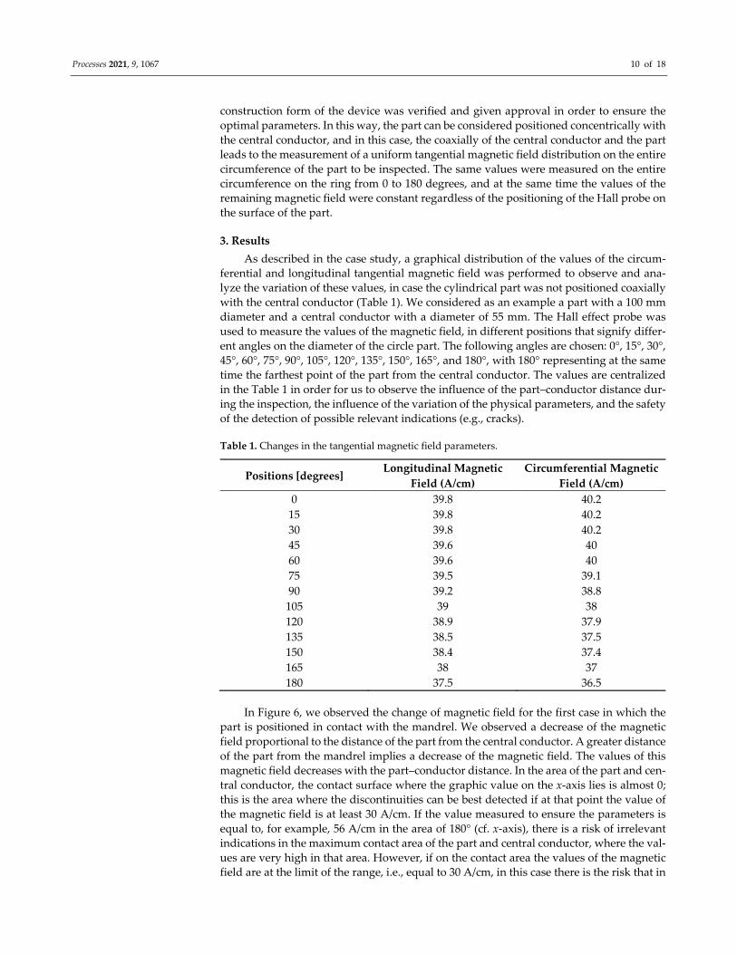
Figure 5 presents the basic elements of standard magnetic particle inspection equip‐
ment.
Figure 5. Equipment components: 1—support soles; 2—basin; 3—electrically operated buttons; 4—
rail for mobile pole; 5—central conductor; 6—fixed pole–coil assembly; 7—mobile pole–coil central
conductor assembly.
Data processing began with the introduction of current intensity parameters for two
magnetization directions (longitudinal and circumferential) until magnetic field values
were obtained between specified ranges. The values were measured with a data acquisi‐
tion system composed of a display with the measured values and a probe for measuring
the values of the magnetic field, provided with a Hall sensor. After the values of the in‐
tensities were established in accordance with the optimal magnetic field for each direction
of magnetization separately (circumferential, longitudinal), the effective inspection took
place on both directions of magnetization.
At the end of this case study, we performed a multicriteria analysis in order to pro‐
pose an optimal design of the device, namely a design that ensures a constant magnetic
field distributed on the surface of the part. Following the multicriteria analysis, the final
Processes 2021, 9, 1067 10 of 18
construction form of the device was verified and given approval in order to ensure the
optimal parameters. In this way, the part can be considered positioned concentrically with
the central conductor, and in this case, the coaxially of the central conductor and the part
leads to the measurement of a uniform tangential magnetic field distribution on the entire
circumference of the part to be inspected. The same values were measured on the entire
circumference on the ring from 0 to 180 degrees, and at the same time the values of the
remaining magnetic field were constant regardless of the positioning of the Hall probe on
the surface of the part.
3. Results
As described in the case study, a graphical distribution of the values of the circum‐
ferential and longitudinal tangential magnetic field was performed to observe and ana‐
lyze the variation of these values, in case the cylindrical part was not positioned coaxially
with the central conductor (Table 1). We considered as an example a part with a 100 mm
diameter and a central conductor with a diameter of 55 mm. The Hall effect probe was
used to measure the values of the magnetic field, in different positions that signify differ‐
ent angles on the diameter of the circle part. The following angles are chosen: 0°, 15°, 30°,
45°, 60°, 75°, 90°, 105°, 120°, 135°, 150°, 165°, and 180°, with 180° representing at the same
time the farthest point of the part from the central conductor. The values are centralized
in the Table 1 in order for us to observe the influence of the part–conductor distance dur‐
ing the inspection, the influence of the variation of the physical parameters, and the safety
of the detection of possible relevant indications (e.g., cracks).
Table 1. Changes in the tangential magnetic field parameters.
Positions [degrees] Longitudinal Magnetic
Field (A/cm)
Circumferential Magnetic
Field (A/cm)
0 39.8 40.2
15 39.8 40.2
30 39.8 40.2
45 39.6 40
60 39.6 40
75 39.5 39.1
90 39.2 38.8
105 39 38
120 38.9 37.9
135 38.5 37.5
150 38.4 37.4
165 38 37
180 37.5 36.5
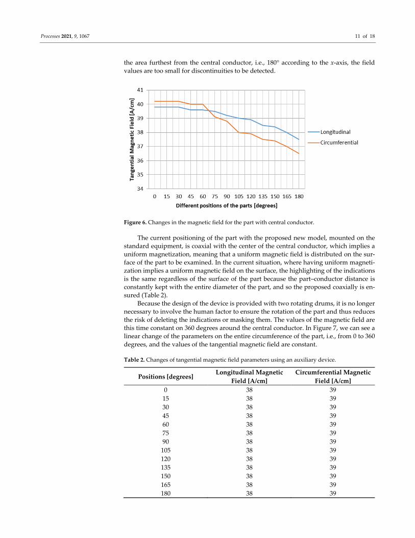
In Figure 6, we observed the change of magnetic field for the first case in which the
part is positioned in contact with the mandrel. We observed a decrease of the magnetic
field proportional to the distance of the part from the central conductor. A greater distance
of the part from the mandrel implies a decrease of the magnetic field. The values of this
magnetic field decreases with the part–conductor distance. In the area of the part and cen‐
tral conductor, the contact surface where the graphic value on the x‐axis lies is almost 0;
this is the area where the discontinuities can be best detected if at that point the value of
the magnetic field is at least 30 A/cm. If the value measured to ensure the parameters is
equal to, for example, 56 A/cm in the area of 180° (cf. x‐axis), there is a risk of irrelevant
indications in the maximum contact area of the part and central conductor, where the val‐
ues are very high in that area. However, if on the contact area the values of the magnetic
field are at the limit of the range, i.e., equal to 30 A/cm, in this case there is the risk that in
Processes 2021, 9, 1067 11 of 18
the area furthest from the central conductor, i.e., 180° according to the x‐axis, the field
values are too small for discontinuities to be detected.
Figure 6. Changes in the magnetic field for the part with central conductor.
The current positioning of the part with the proposed new model, mounted on the
standard equipment, is coaxial with the center of the central conductor, which implies a
uniform magnetization, meaning that a uniform magnetic field is distributed on the sur‐
face of the part to be examined. In the current situation, where having uniform magneti‐
zation implies a uniform magnetic field on the surface, the highlighting of the indications
is the same regardless of the surface of the part because the part–conductor distance is
constantly kept with the entire diameter of the part, and so the proposed coaxially is en‐
sured (Table 2).
Because the design of the device is provided with two rotating drums, it is no longer
necessary to involve the human factor to ensure the rotation of the part and thus reduces
the risk of deleting the indications or masking them. The values of the magnetic field are
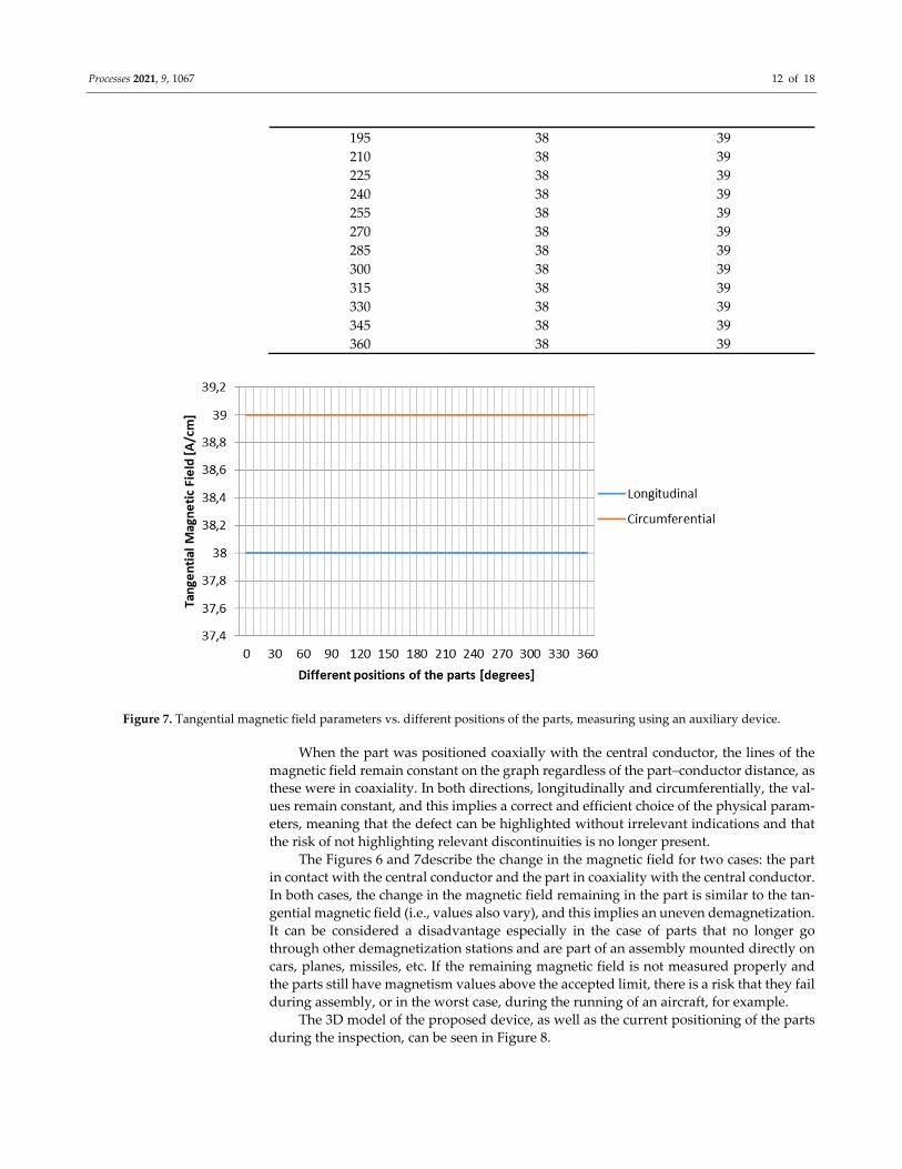
this time constant on 360 degrees around the central conductor. In Figure 7, we can see a
linear change of the parameters on the entire circumference of the part, i.e., from 0 to 360
degrees, and the values of the tangential magnetic field are constant.
Table 2. Changes of tangential magnetic field parameters using an auxiliary device.
Positions [degrees] Longitudinal Magnetic
Field [A/cm]
Circumferential Magnetic
Field [A/cm]
0 38 39
15 38 39
30 38 39
45 38 39
60 38 39
75 38 39
90 38 39
105 38 39
120 38 39
135 38 39
150 38 39
165 38 39
180 38 39
Processes 2021, 9, 1067 12 of 18
195 38 39
210 38 39
225 38 39
240 38 39
255 38 39
270 38 39
285 38 39
300 38 39
315 38 39
330 38 39
345 38 39
360 38 39
Figure 7. Tangential magnetic field parameters vs. different positions of the parts, measuring using an auxiliary device.
When the part was positioned coaxially with the central conductor, the lines of the
magnetic field remain constant on the graph regardless of the part–conductor distance, as
these were in coaxiality. In both directions, longitudinally and circumferentially, the val‐
ues remain constant, and this implies a correct and efficient choice of the physical param‐
eters, meaning that the defect can be highlighted without irrelevant indications and that
the risk of not highlighting relevant discontinuities is no longer present.
The Figures 6 and 7describe the change in the magnetic field for two cases: the part
in contact with the central conductor and the part in coaxiality with the central conductor.
In both cases, the change in the magnetic field remaining in the part is similar to the tan‐
gential magnetic field (i.e., values also vary), and this implies an uneven demagnetization.
It can be considered a disadvantage especially in the case of parts that no longer go
through other demagnetization stations and are part of an assembly mounted directly on
cars, planes, missiles, etc. If the remaining magnetic field is not measured properly and
the parts still have magnetism values above the accepted limit, there is a risk that they fail
during assembly, or in the worst case, during the running of an aircraft, for example.
The 3D model of the proposed device, as well as the current positioning of the parts
during the inspection, can be seen in Figure 8.
Processes 2021, 9, 1067 13 of 18
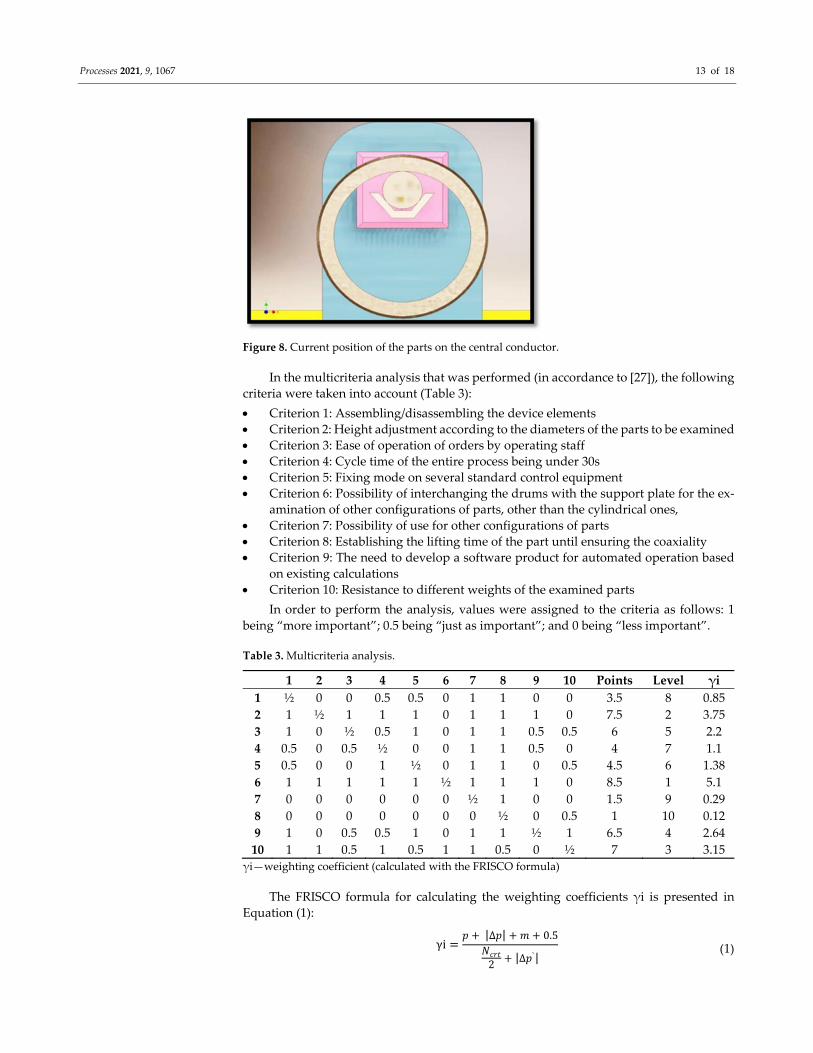
Figure 8. Current position of the parts on the central conductor.
In the multicriteria analysis that was performed (in accordance to [27]), the following
criteria were taken into account (Table 3):
Criterion 1: Assembling/disassembling the device elements
Criterion 2: Height adjustment according to the diameters of the parts to be examined
Criterion 3: Ease of operation of orders by operating staff
Criterion 4: Cycle time of the entire process being under 30s
Criterion 5: Fixing mode on several standard control equipment
Criterion 6: Possibility of interchanging the drums with the support plate for the ex‐
amination of other configurations of parts, other than the cylindrical ones,
Criterion 7: Possibility of use for other configurations of parts
Criterion 8: Establishing the lifting time of the part until ensuring the coaxiality
Criterion 9: The need to develop a software product for automated operation based
on existing calculations
Criterion 10: Resistance to different weights of the examined parts
In order to perform the analysis, values were assigned to the criteria as follows: 1
being “more important”; 0.5 being “just as important”; and 0 being “less important”.
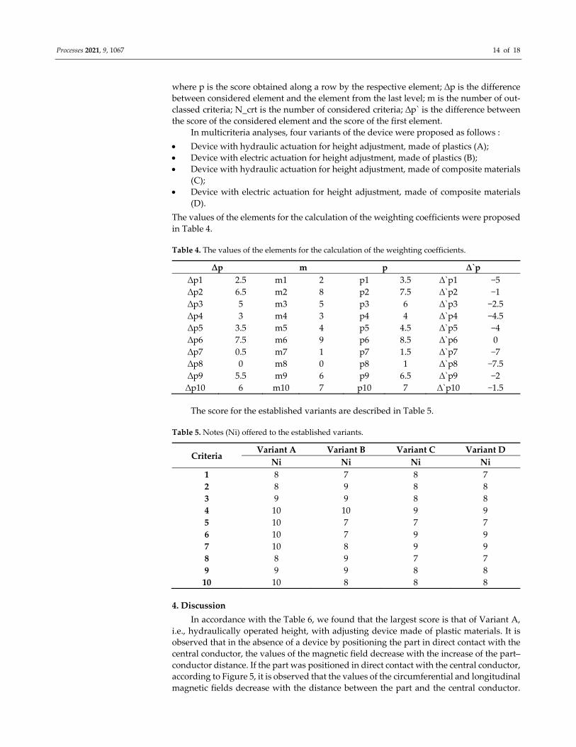
Table 3. Multicriteria analysis.
1 2 3 4 5 6 7 8 9 10 Points Level γi
1 ½ 0 0 0.5 0.5 0 1 1 0 0 3.5 8 0.85
2 1 ½ 1 1 1 0 1 1 1 0 7.5 2 3.75
3 1 0 ½ 0.5 1 0 1 1 0.5 0.5 6 5 2.2
4 0.5 0 0.5 ½ 0 0 1 1 0.5 0 4 7 1.1
5 0.5 0 0 1 ½ 0 1 1 0 0.5 4.5 6 1.38
6 1 1 1 1 1 ½ 1 1 1 0 8.5 1 5.1
7 0 0 0 0 0 0 ½ 1 0 0 1.5 9 0.29
8 0 0 0 0 0 0 0 ½ 0 0.5 1 10 0.12
9 1 0 0.5 0.5 1 0 1 1 ½ 1 6.5 4 2.64
10 1 1 0.5 1 0.5 1 1 0.5 0 ½ 7 3 3.15
γi—weighting coefficient (calculated with the FRISCO formula)
The FRISCO formula for calculating the weighting coefficients γi is presented in
Equation (1):
γi𝑝 |∆𝑝| 𝑚 0.5
𝑁𝑐𝑟𝑡2
|∆𝑝`| (1)
Processes 2021, 9, 1067 14 of 18
where p is the score obtained along a row by the respective element; ∆p is the difference
between considered element and the element from the last level; m is the number of out‐
classed criteria; N_crt is the number of considered criteria; ∆p` is the difference between
the score of the considered element and the score of the first element.
In multicriteria analyses, four variants of the device were proposed as follows :
Device with hydraulic actuation for height adjustment, made of plastics (A);
Device with electric actuation for height adjustment, made of plastics (B);
Device with hydraulic actuation for height adjustment, made of composite materials
(C);
Device with electric actuation for height adjustment, made of composite materials
(D).
The values of the elements for the calculation of the weighting coefficients were proposed
in Table 4.
Table 4. The values of the elements for the calculation of the weighting coefficients.
∆p m p ∆`p
∆p1 2.5 m1 2 p1 3.5 ∆`p1 −5
∆p2 6.5 m2 8 p2 7.5 ∆`p2 −1
∆p3 5 m3 5 p3 6 ∆`p3 −2.5
∆p4 3 m4 3 p4 4 ∆`p4 −4.5
∆p5 3.5 m5 4 p5 4.5 ∆`p5 −4
∆p6 7.5 m6 9 p6 8.5 ∆`p6 0
∆p7 0.5 m7 1 p7 1.5 ∆`p7 −7
∆p8 0 m8 0 p8 1 ∆`p8 −7.5
∆p9 5.5 m9 6 p9 6.5 ∆`p9 −2
∆p10 6 m10 7 p10 7 ∆`p10 −1.5
The score for the established variants are described in Table 5.
Table 5. Notes (Ni) offered to the established variants.
Criteria Variant A Variant B Variant C Variant D
Ni Ni Ni Ni
1 8 7 8 7
2 8 9 8 8
3 9 9 8 8
4 10 10 9 9
5 10 7 7 7
6 10 7 9 9
7 10 8 9 9
8 8 9 7 7
9 9 9 8 8
10 10 8 8 8
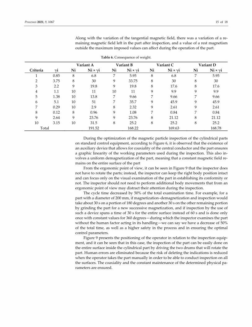
4. Discussion
In accordance with the Table 6, we found that the largest score is that of Variant A,
i.e., hydraulically operated height, with adjusting device made of plastic materials. It is
observed that in the absence of a device by positioning the part in direct contact with the
central conductor, the values of the magnetic field decrease with the increase of the part–
conductor distance. If the part was positioned in direct contact with the central conductor,
according to Figure 5, it is observed that the values of the circumferential and longitudinal
magnetic fields decrease with the distance between the part and the central conductor.
Processes 2021, 9, 1067 15 of 18
Along with the variation of the tangential magnetic field, there was a variation of a re‐
maining magnetic field left in the part after inspection, and a value of a rest magnetism
outside the maximum imposed values can affect during the operation of the part.
Table 6. Consequence of weight.
Variant A Variant B Variant C Variant D
Criteria γi Ni Ni × γi Ni Ni × γi Ni Ni × γi Ni Ni × γi
1 0.85 8 6.8 7 5.95 8 6.8 7 5.95
2 3.75 8 30 9 33.75 8 30 8 30
3 2.2 9 19.8 9 19.8 8 17.6 8 17.6
4 1.1 10 11 10 11 9 9.9 9 9.9
5 1.38 10 13.8 7 9.66 7 9.66 7 9.66
6 5.1 10 51 7 35.7 9 45.9 9 45.9
7 0.29 10 2.9 8 2.32 9 2.61 9 2.61
8 0.12 8 0.96 9 1.08 7 0.84 7 0.84
9 2.64 9 23.76 9 23.76 8 21.12 8 21.12
10 3.15 10 31.5 8 25.2 8 25.2 8 25.2
Total 191.52 168.22 169.63 168.78
During the optimization of the magnetic particle inspection of the cylindrical parts
on standard control equipment, according to Figure 6, it is observed that the existence of
an auxiliary device that allows for coaxiality of the central conductor and the part ensures
a graphic linearity of the working parameters used during the inspection. This also in‐
volves a uniform demagnetization of the part, meaning that a constant magnetic field re‐
mains on the entire surface of the part
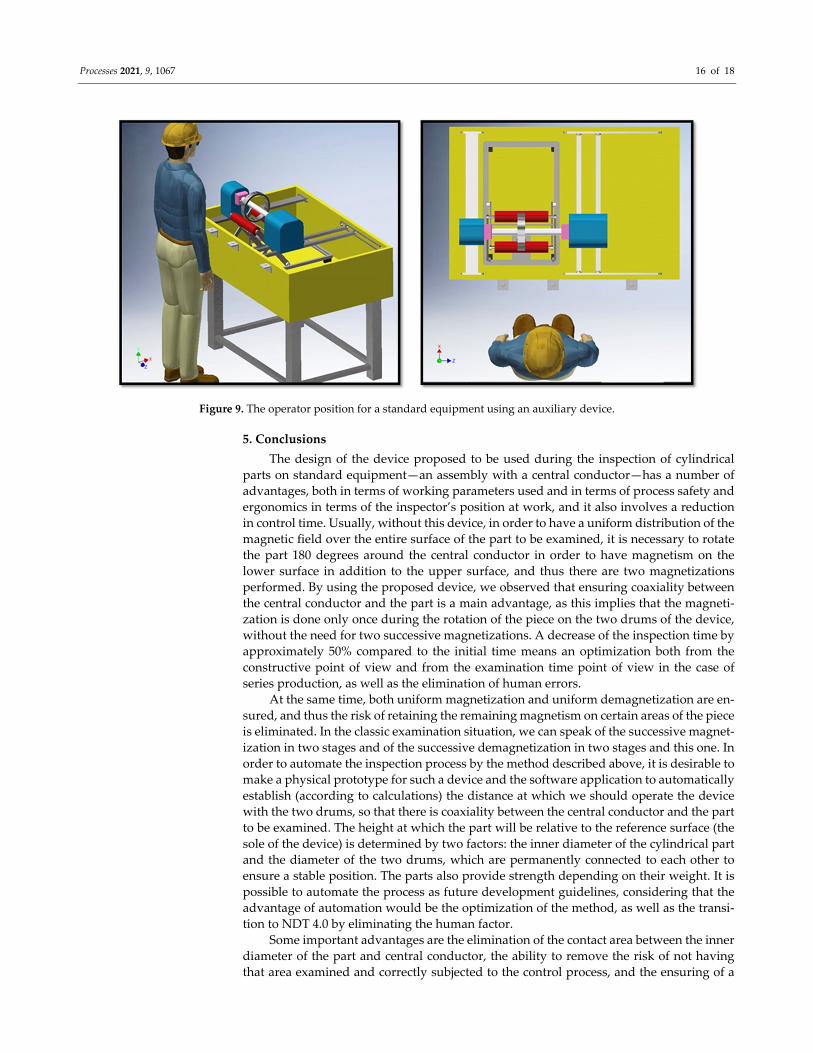
From the ergonomic point of view, it can be seen in Figure 9 that the inspector does
not have to rotate the parts; instead, the inspector can keep the right body position intact
and can focus only on the visual examination of the part in establishing its conformity or
not. The inspector should not need to perform additional body movements that from an
ergonomic point of view may distract their attention during the inspection.
The cycle time decreased by 50% of the total examination time. For example, for a
part with a diameter of 200 mm, if magnetization–demagnetization and inspection would
take about 30 s on a portion of 180 degrees and another 30 s on the other remaining portion
by grinding the part for a new successive magnetization, and if inspection by the use of
such a device spans a time of 30 s for the entire surface instead of 60 s and is done only
once with constant values for 360 degrees—during which the inspector examines the part
without the human factor acting in its handling—we can say we have a decrease of 50%
of the total time, as well as a higher safety in the process and in ensuring the optimal
control parameters.
Figure 9 presents the positioning of the operator in relation to the inspection equip‐
ment, and it can be seen that in this case, the inspection of the part can be easily done on
the entire surface inside the cylindrical part by driving the two drums that will rotate the
part. Human errors are eliminated because the risk of deleting the indications is reduced
when the operator takes the part manually in order to be able to conduct inspection on all
the surfaces. The coaxiality and the constant maintenance of the determined physical pa‐
rameters are ensured.
Processes 2021, 9, 1067 16 of 18
Figure 9. The operator position for a standard equipment using an auxiliary device.
5. Conclusions
The design of the device proposed to be used during the inspection of cylindrical
parts on standard equipment—an assembly with a central conductor—has a number of
advantages, both in terms of working parameters used and in terms of process safety and
ergonomics in terms of the inspector’s position at work, and it also involves a reduction
in control time. Usually, without this device, in order to have a uniform distribution of the
magnetic field over the entire surface of the part to be examined, it is necessary to rotate
the part 180 degrees around the central conductor in order to have magnetism on the
lower surface in addition to the upper surface, and thus there are two magnetizations
performed. By using the proposed device, we observed that ensuring coaxiality between
the central conductor and the part is a main advantage, as this implies that the magneti‐
zation is done only once during the rotation of the piece on the two drums of the device,
without the need for two successive magnetizations. A decrease of the inspection time by
approximately 50% compared to the initial time means an optimization both from the
constructive point of view and from the examination time point of view in the case of
series production, as well as the elimination of human errors.
At the same time, both uniform magnetization and uniform demagnetization are en‐
sured, and thus the risk of retaining the remaining magnetism on certain areas of the piece
is eliminated. In the classic examination situation, we can speak of the successive magnet‐
ization in two stages and of the successive demagnetization in two stages and this one. In
order to automate the inspection process by the method described above, it is desirable to
make a physical prototype for such a device and the software application to automatically
establish (according to calculations) the distance at which we should operate the device
with the two drums, so that there is coaxiality between the central conductor and the part
to be examined. The height at which the part will be relative to the reference surface (the
sole of the device) is determined by two factors: the inner diameter of the cylindrical part
and the diameter of the two drums, which are permanently connected to each other to
ensure a stable position. The parts also provide strength depending on their weight. It is
possible to automate the process as future development guidelines, considering that the
advantage of automation would be the optimization of the method, as well as the transi‐
tion to NDT 4.0 by eliminating the human factor.
Some important advantages are the elimination of the contact area between the inner
diameter of the part and central conductor, the ability to remove the risk of not having
that area examined and correctly subjected to the control process, and the ensuring of a
Processes 2021, 9, 1067 17 of 18
constant magnetic field on the entire circumference of the part. For example, in the case
of a cylindrical part with a large diameter subject to nondestructive testing on equipment
without a fastening device, in the moment of checking the intensity of the two magnetic
fields, if the Hall sensor is positioned at the top of the ring (part in contact with central
conductor), the value indicated by the device will be larger than the one at the bottom
coming out of the area of the central conductor. In this case, the magnetization of the part
is not performed evenly over its entire surface; to have a correct magnetization, it is nec‐
essary to rotate the part by 180 degrees. This difference in the intensity of the magnetic
field flux is obvious because in the area of the central conductor, the value of the field is
always higher than that at the extremities.
One of the disadvantages is that the device is limited only to the examination of cy‐
lindrical parts on standard control equipment, and the limitation is for these part config‐
urations. If the geometry of the part is different and the thickness/radius varies greatly,
then depending on the values of the magnetic field, it will have to be magnified several
times, but without this device, the part may need to be in direct contact with the central
conductor to ensure optimal physics parameters. If the values of the magnetic field from
one thickness to another do not differ much and are in the optimal range (30–60 A/cm),
then the inspection must be in good condition. There is the possibility of positioning flow
indicators (with artificial cracks of different dimensions) on the surface of the part on the
area of small thickness and large, and during magnetization in addition to the parameters
of the magnetic field, it can be seen how well highlighted or not certain cracks are.
A possible future direction of research is to expand the range of products that can be
examined to ensure a constant magnetic field, possibly for parts with variable geometry.
Another possible development directive can involve mounting Hall sensors on the two
drive drums so that the values of the magnetic field and of the remaining magnetism are
measured and shown on a display. At the same time, this measurement of the value of the
magnetic field of the remaining magnetism could be transmitted wirelessly to an elec‐
tronic application to monitor the process and its parameters from reference to reference.
All these represent future directions of improvement and optimization that can lead to
the development of manufacturing processes and control processes.
Author Contributions: Conceptualization, A.I.S., G.O. and L.P.; methodology, A.I.S. and L.P.; re‐
sources, A.I.S. and L.P.; writing—original draft preparation, A.I.S.; writing—review and editing,
A.I.S., G.O., and L.P.; visualization, A.I.S., G.O. and L.P.; supervision, G.O. and L.P. All authors have
read and agreed to the published version of the manuscript.
Funding: This research received no external funding.
Institutional Review Board Statement: Not applicable.
Informed Consent Statement: Not applicable.
Conflicts of Interest: The authors declare no conflict of interest.
References
1. Chakraborty, D.; McGovern, M.E. NDE 4.0: Smart NDE. In Proceedings of the 2019 IEEE International Conference on Prognos‐
tics and Health Management (ICPHM), San Francisco, CA, USA, 17–20 June 2019.
2. Im, K.‐H.; Kim, S.‐K.; Jung, J.‐A.; Cho, Y.‐T.; Woo, Y.‐D.; Chiou, C.‐P. NDE Detection Techniques and Characterization of Alu‐
minum Wires Embedded in Honeycomb Sandwich Composite Panels Using Terahertz Waves. Materials 2019, 12, 1264.
3. He, M.; Matsumoto, T.; Takeda, S.; Uchimoto, T.; Takagi, T.; Miki, H.; Chen, H.‐E.; Xie, S.; Chen, Z. Nondestructive evaluation
of plastic damage in a RAFM steel considering the influence of loading history. J. Nucl. Mater. 2019, 523, 248–259.
4. Miwa, T. Non‐Destructive and Quantitative Evaluation of Rebar Corrosion by a Vibro‐Doppler Radar Method. Sensors 2021, 21,
2546.
5. Kostroun, T.; Dvořák, M. Application of the Pulse Infrared Thermography Method for Nondestructive Evaluation of Composite
Aircraft Adhesive Joints. Materials 2021, 14, 533.
6. Vrana, J.; Singh, R. NDE 4.0—A Design Thinking Perspective. J. Nondestruct. Eval. 2021, 40, 8.
7. Abell, J.A.; Chakraborty, D.; Escobar, C.A.; Im, K.H.; Wegner, D.M.; Wincek, M.A. Big data driven manufacturing—Process‐
monitoring‐forquality philosophy. J. Manuf. Sci. Eng. 2017, 139, 1–12.
Processes 2021, 9, 1067 18 of 18
8. He, M.; Shi, P.; Xie, S.; Chen, Z.; Uchimoto, T.; Takagi, T. A numerical simulation method of nonlinear magnetic flux leakage
testing signals for nondestructive evaluation of plastic deformation in a ferromagnetic material. Mech. Syst. Signal Process. 2021,
155, 107670.
9. Shi, P.; Jin, K.; Zheng, X. A magnetomechanical model for the magnetic memory method. Int. J. Mech. Sci. 2017, 124–125, 229–
241.
10. Usarek, Z.; Augustyniak, B. Evaluation of the impact of geometry and plastic deformation on the stray magnetic field around
the bone‐shaped sample. Int. J. Appl. Electromagn. Mech. 2015, 48, 195–199.
11. Shi, P.; Su, S.; Chen, Z. Overview of Researches on the Nondestructive Testing Method of Metal Magnetic Memory: Status and
Challenges. J. Nondestruct. Eval. 2020, 39, 1–37.
12. Boller, C.; Altpeter, I.; Dobmann, Electromagnetism as a means for understanding materials mechanics phenomena in magnetic
materials. Mater. Werkst. 2011, 42, 269–278.
13. Dovbov, A. The method of metal magnetic memory—The new trend in engineering diagnostics. Weld. World 2005, 49, 314–319.
14. Vrana, J. NDE perception and emerging reality: NDE 40 value extraction. Mater. Eval. 2020, 78, 835–851.
15. Vrana, J.; Kadau, K.; Amann, C. Smart data analysis of the results of ultrasonic inspections for probabilistic fracture mechanics.
VGB PowerTech 2018, 7, 38–42.
16. Escobar, C.A.; Wincek, M.A.; Chakraborty, D.; Morales‐Menendez, R. Process‐monitoring‐for‐quality—Applications. Manuf.
Lett. 2018, 16, 14–17.
17. Bray, D.E.; Stanley, R.K. Nondestructive Evaluation: A Tool in Design, Manufacturing and Service; CRC Press: Boca Raton, FL, USA,
1998.
18. Sola, M.; Lagüela, S.; Riveiro, B.; Lorenzo, H. Non‐destructive testing for the analysis of moisture in the masonry arch bridge of
Lubians (Spain). Struct. Control. Health Monit. 2013, 20, 1366–1376.
19. Diamanti, N.; Redman, D. Field observations and numerical models of GPR response from vertical pavement cracks. J. Appl.
Geophys. 2021, 81, 106–116.
20. Rasol, M.A.; Pérez‐Gracia, V.; Fernandes, F.M.; Pais, H.C.; Solla, M.; Santos, C. NDT assessment of rigid pavement damages
with ground penetrating radar: Laboratory and field tests. Int. J. Pavement Eng. 2020, 21, 1–16.
21. Rasol, M.A.; Pérez‐Gracia, V.; Fernandes, F.M.; Pais, J.C.; Santos‐Assunçao, S.; Santos, C.; Sossa, V. GPR laboratory tests and
numerical models to characterize cracks in cement concrete specimens, exemplifying damage in rigid pavement. Measurement
2020, 158, 107662.
22. Rasol, M.A.; Pérez‐Gracia, V.; Solla, M.; Pais, H.C.; Fernandes, F.M.; Santos, C. An experimental and numerical approach to
combine Ground Penetrating Radar and computational modeling for the identification of early cracking in cement concrete
pavements. NDT E Int. 2020, 115, 102293.
23. Fernandes, F.; Pais, J. Laboratory observation of cracks in road pavements with GPR. Constr. Build. Mater. 2017, 154, 1130–1138.
24. Schimleck, L.; Dahlen, J.; Apiolaza, L.A.; Downes, G.; Emms, G.; Evans, R.; Moore, J.; Pâques, L.; Van den Bulcke, J.; Wang, X.
Non‐Destructive Evaluation Techniques and What They Tell Us about Wood Property Variation. Forests 2019, 10, 728.
25. Meyendorf, N.G.; Bond, L.J.; Curtis‐Beard, J.; Heilmann, S. NDE 4.0—NDE for the 21st century—The internet of things and
cyber physical systems will revolutionize NDE. In Proceedings of the 15th Asia Pacific Conference for Non‐Destructive Testing
(APCNDT2017), Singapore, 13–17 November 2017.
26. Liu, Y.; Hu, B.; Lan, X.; Fu, P. Micromagnetic characteristic changes and mechanism induced by plastic deformation of austenitic
stainless steel. Mater. Today Commun. 2021, 27, 102188.
27. Zavadskas, E.K.; Antucheviciene, J., Chatterjee, P. Multiple‐Criteria Decision‐Making (MCDM) Techniques for Business Pro‐
cesses Information Management. Information 2019, 10, 4.