copias asociativas siemens nx
TRANSCRIPT
[NX8-HELP] ASSOCIACTIVE COPY 1
Associactive Copy drive24ward (meslab.org/mes)
Associative Copy
View a topic
Pattern Feature
Extract Body
Composite Curve
Mirror Feature
Mirror Body
Instance Geometry
Promote Body
Instance Feature
1. Pattern Feature
Use the Pattern Feature command to create patterns of features (linear, circular, polygon, etc.) with
various options for defining pattern boundaries, orientation of instances, clocking and variance.
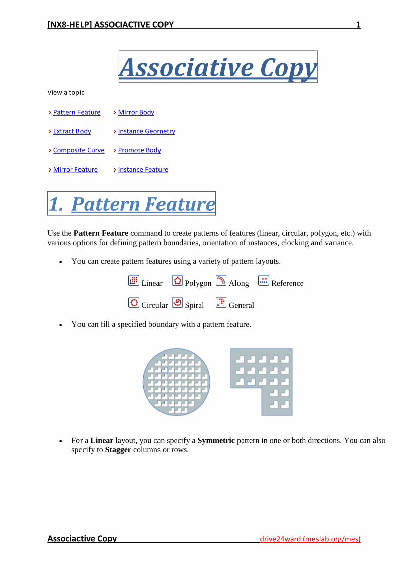
You can create pattern features using a variety of pattern layouts.
Linear
Circular
Polygon
Spiral
Along
General
Reference
You can fill a specified boundary with a pattern feature.
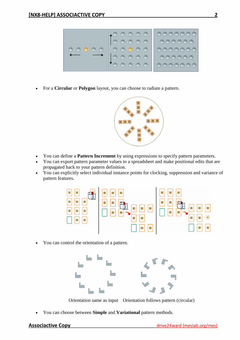
For a Linear layout, you can specify a Symmetric pattern in one or both directions. You can also
specify to Stagger columns or rows.
[NX8-HELP] ASSOCIACTIVE COPY 2
Associactive Copy drive24ward (meslab.org/mes)
For a Circular or Polygon layout, you can choose to radiate a pattern.
You can define a Pattern Increment by using expressions to specify pattern parameters.
You can export pattern parameter values to a spreadsheet and make positional edits that are
propagated back to your pattern definition.
You can explicitly select individual instance points for clocking, suppression and variance of
pattern features.
You can control the orientation of a pattern.
Orientation same as input
Orientation follows pattern (circular)
You can choose between Simple and Variational pattern methods.
[NX8-HELP] ASSOCIACTIVE COPY 3
Associactive Copy drive24ward (meslab.org/mes)
Where do I find it?
Application Modeling and Shape Studio
Prerequisite History mode
Toolbar Feature→Pattern Feature
Menu Insert→Associative Copy→Pattern Feature
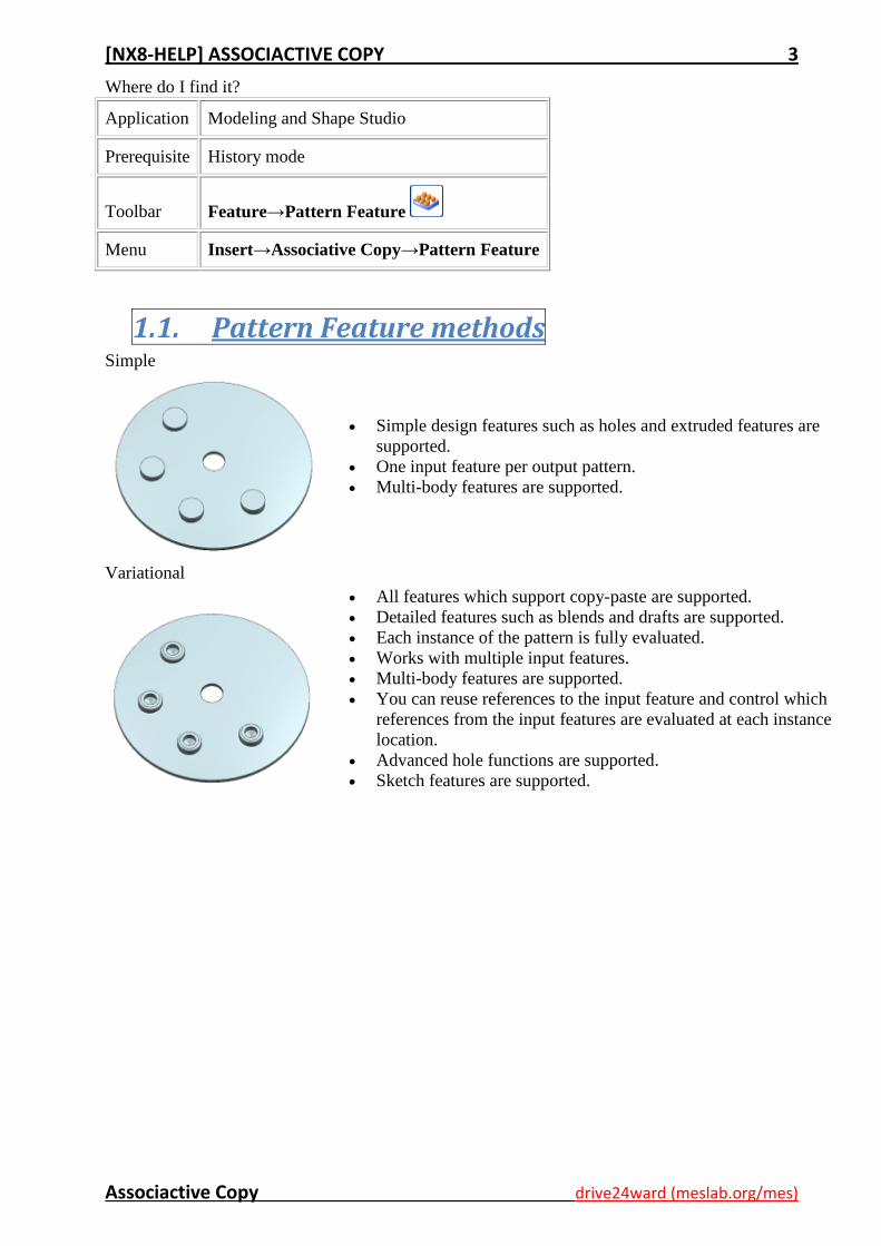
1.1. Pattern Feature methods Simple
Simple design features such as holes and extruded features are
supported.
One input feature per output pattern.
Multi-body features are supported.
Variational
All features which support copy-paste are supported.
Detailed features such as blends and drafts are supported.
Each instance of the pattern is fully evaluated.
Works with multiple input features.
Multi-body features are supported.
You can reuse references to the input feature and control which
references from the input features are evaluated at each instance
location.
Advanced hole functions are supported.
Sketch features are supported.
[NX8-HELP] ASSOCIACTIVE COPY 4
Associactive Copy drive24ward (meslab.org/mes)
1.2. Create a linear pattern of features in two
directions
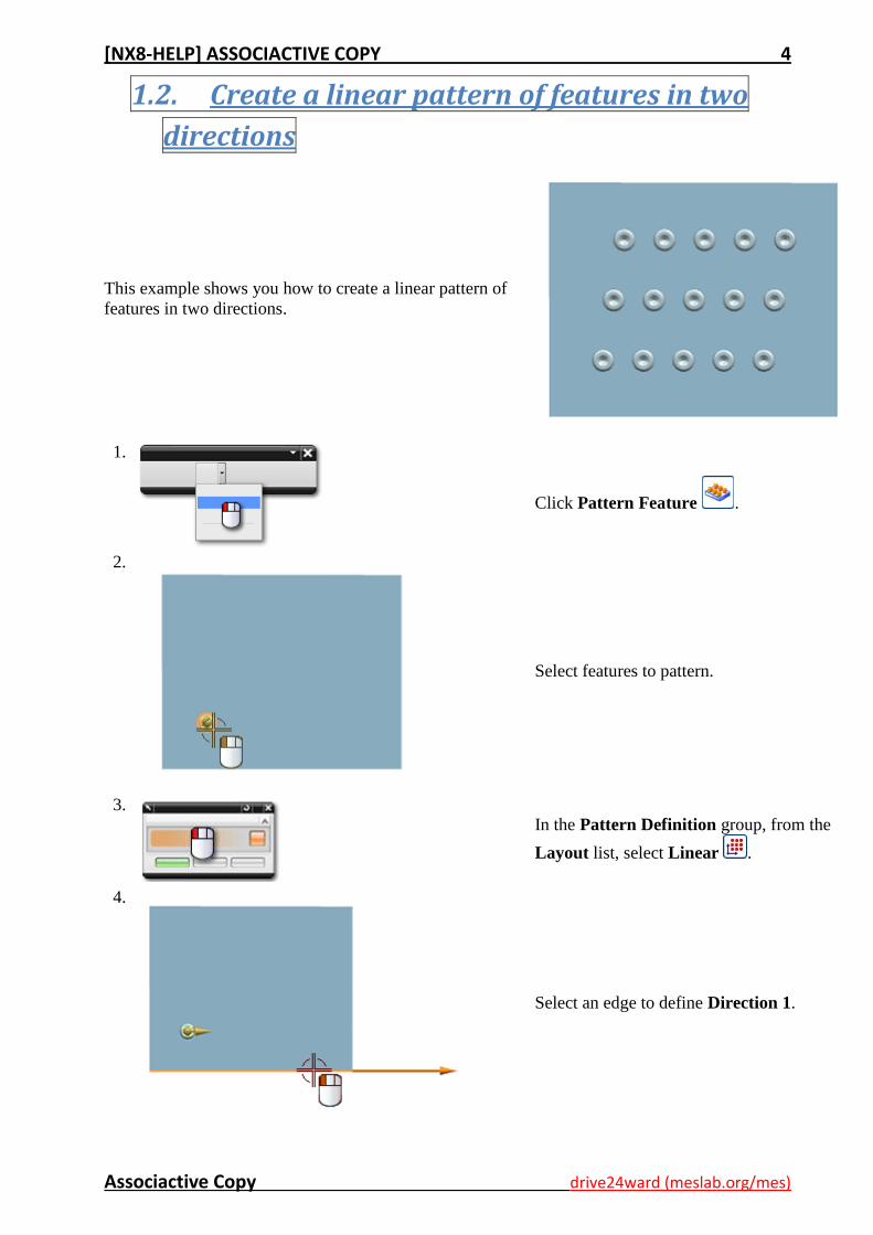
This example shows you how to create a linear pattern of
features in two directions.
1.
Click Pattern Feature .
2.
Select features to pattern.
3.
In the Pattern Definition group, from the
Layout list, select Linear .
4.
Select an edge to define Direction 1.
[NX8-HELP] ASSOCIACTIVE COPY 5
Associactive Copy drive24ward (meslab.org/mes)
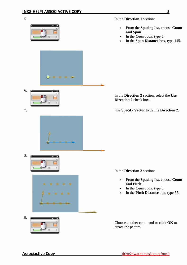
5.
In the Direction 1 section:
From the Spacing list, choose Count
and Span.
In the Count box, type 5.
In the Span Distance box, type 145.
6.
In the Direction 2 section, select the Use
Direction 2 check box.
7.
Use Specify Vector to define Direction 2.
8.
In the Direction 2 section:
From the Spacing list, choose Count
and Pitch.
In the Count box, type 3.
In the Pitch Distance box, type 55.
9.
Choose another command or click OK to
create the pattern.
[NX8-HELP] ASSOCIACTIVE COPY 6
Associactive Copy drive24ward (meslab.org/mes)
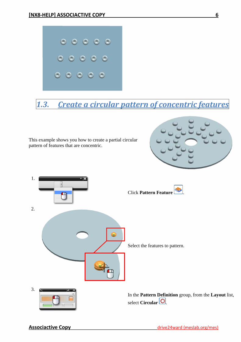
1.3. Create a circular pattern of concentric features
This example shows you how to create a partial circular
pattern of features that are concentric.
1.
Click Pattern Feature .
2.
Select the features to pattern.
3.
In the Pattern Definition group, from the Layout list,
select Circular .

[NX8-HELP] ASSOCIACTIVE COPY 7
Associactive Copy drive24ward (meslab.org/mes)
4.
Under Rotation Axis, click Specify Vector.
5.
Specify a vector of rotation.
6.
Specify a point of rotation.
7.
Under Angular Direction:
From the Spacing list, choose Pitch and Span.
From the Define Pitch As list, choose Angle.
In the Pitch Angle box, type 30.
In the Span Angle box, type 270.
[NX8-HELP] ASSOCIACTIVE COPY 8
Associactive Copy drive24ward (meslab.org/mes)
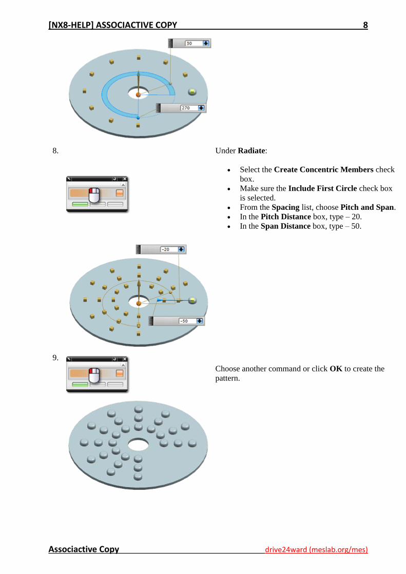
8.
Under Radiate:
Select the Create Concentric Members check
box.
Make sure the Include First Circle check box
is selected.
From the Spacing list, choose Pitch and Span.
In the Pitch Distance box, type – 20.
In the Span Distance box, type – 50.
9.
Choose another command or click OK to create the
pattern.
[NX8-HELP] ASSOCIACTIVE COPY 9
Associactive Copy drive24ward (meslab.org/mes)
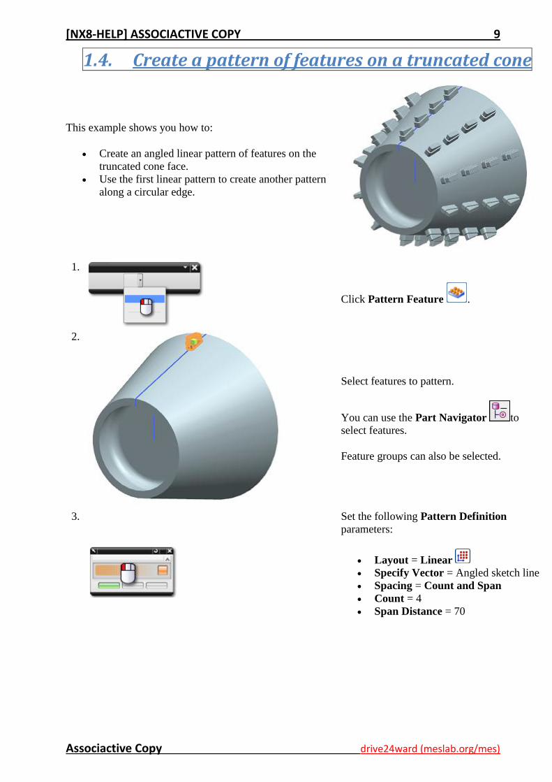
1.4. Create a pattern of features on a truncated cone
This example shows you how to:
Create an angled linear pattern of features on the
truncated cone face.
Use the first linear pattern to create another pattern
along a circular edge.
1.
Click Pattern Feature .
2.
Select features to pattern.
You can use the Part Navigator to
select features.
Feature groups can also be selected.
3. Set the following Pattern Definition
parameters:
Layout = Linear
Specify Vector = Angled sketch line
Spacing = Count and Span
Count = 4
Span Distance = 70
[NX8-HELP] ASSOCIACTIVE COPY 10
Associactive Copy drive24ward (meslab.org/mes)
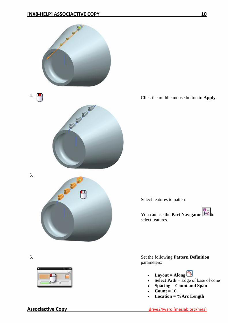
4.
Click the middle mouse button to Apply.
5.
Select features to pattern.
You can use the Part Navigator to
select features.
6. Set the following Pattern Definition
parameters:
Layout = Along
Select Path = Edge of base of cone
Spacing = Count and Span
Count = 10
Location = %Arc Length
[NX8-HELP] ASSOCIACTIVE COPY 11
Associactive Copy drive24ward (meslab.org/mes)
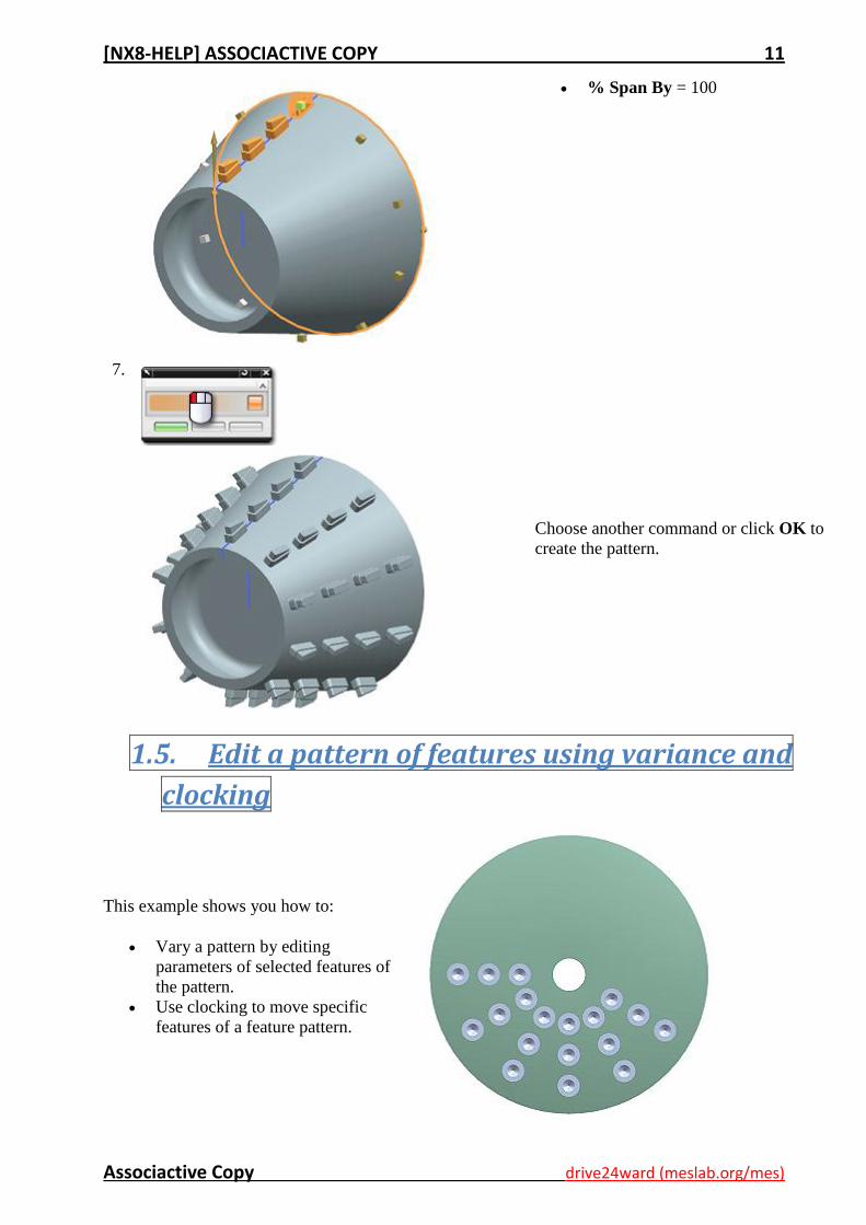
% Span By = 100
7.
Choose another command or click OK to
create the pattern.
1.5. Edit a pattern of features using variance and
clocking
This example shows you how to:
Vary a pattern by editing
parameters of selected features of
the pattern.
Use clocking to move specific
features of a feature pattern.
[NX8-HELP] ASSOCIACTIVE COPY 12
Associactive Copy drive24ward (meslab.org/mes)
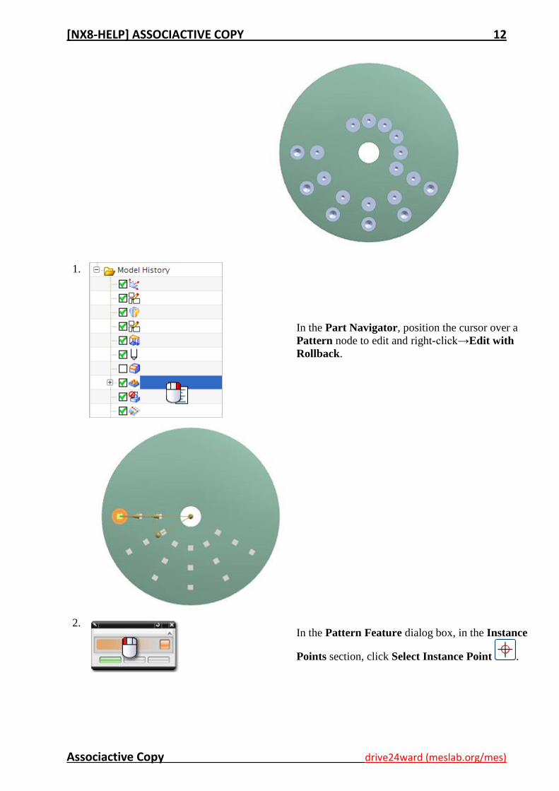
1.
In the Part Navigator, position the cursor over a
Pattern node to edit and right-click→Edit with
Rollback.
2.
In the Pattern Feature dialog box, in the Instance
Points section, click Select Instance Point .
[NX8-HELP] ASSOCIACTIVE COPY 13
Associactive Copy drive24ward (meslab.org/mes)
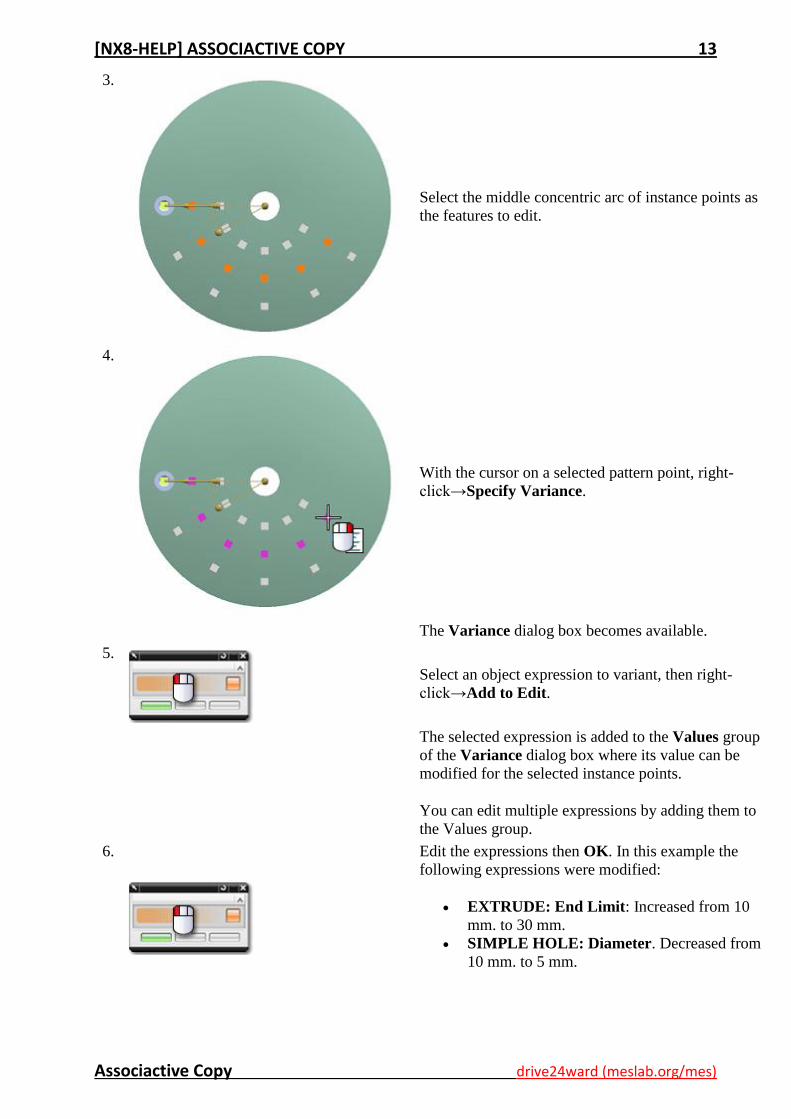
3.
Select the middle concentric arc of instance points as
the features to edit.
4.
With the cursor on a selected pattern point, right-
click→Specify Variance.
The Variance dialog box becomes available.
5.
Select an object expression to variant, then right-
click→Add to Edit.
The selected expression is added to the Values group
of the Variance dialog box where its value can be
modified for the selected instance points.
You can edit multiple expressions by adding them to
the Values group.
6.
Edit the expressions then OK. In this example the
following expressions were modified:
EXTRUDE: End Limit: Increased from 10
mm. to 30 mm.
SIMPLE HOLE: Diameter. Decreased from
10 mm. to 5 mm.
[NX8-HELP] ASSOCIACTIVE COPY 14
Associactive Copy drive24ward (meslab.org/mes)
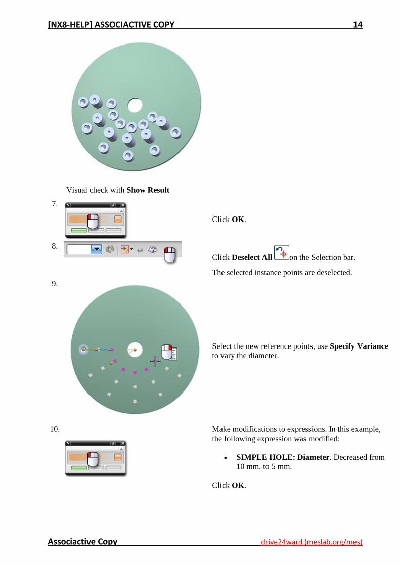
Visual check with Show Result
7.
Click OK.
8.
Click Deselect All on the Selection bar.
The selected instance points are deselected.
9.
Select the new reference points, use Specify Variance
to vary the diameter.
10.
Make modifications to expressions. In this example,
the following expression was modified:
SIMPLE HOLE: Diameter. Decreased from
10 mm. to 5 mm.
Click OK.
[NX8-HELP] ASSOCIACTIVE COPY 15
Associactive Copy drive24ward (meslab.org/mes)
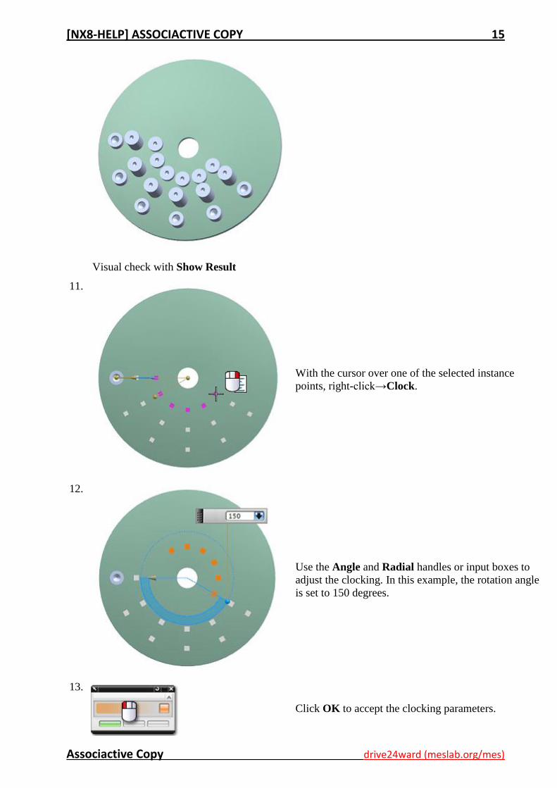
Visual check with Show Result
11.
With the cursor over one of the selected instance
points, right-click→Clock.
12.
Use the Angle and Radial handles or input boxes to
adjust the clocking. In this example, the rotation angle
is set to 150 degrees.
13.
Click OK to accept the clocking parameters.
[NX8-HELP] ASSOCIACTIVE COPY 16
Associactive Copy drive24ward (meslab.org/mes)
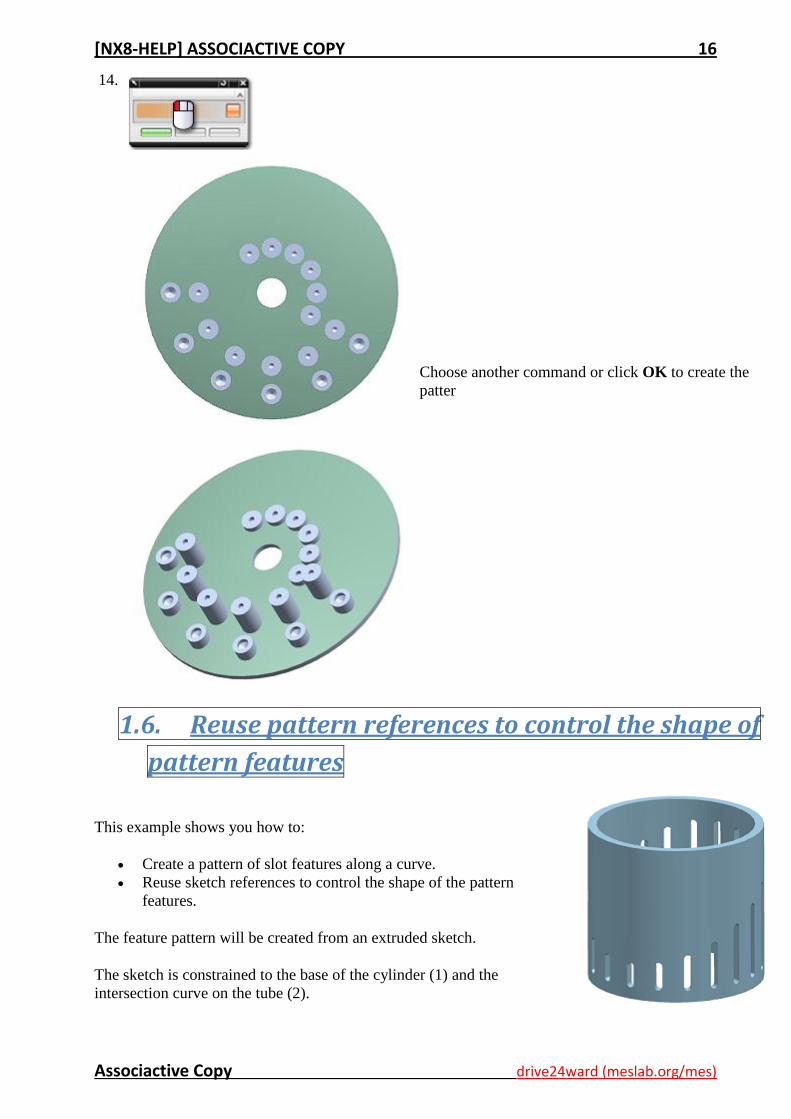
14.
Choose another command or click OK to create the
patter
1.6. Reuse pattern references to control the shape of
pattern features
This example shows you how to:
Create a pattern of slot features along a curve.
Reuse sketch references to control the shape of the pattern
features.
The feature pattern will be created from an extruded sketch.
The sketch is constrained to the base of the cylinder (1) and the
intersection curve on the tube (2).
[NX8-HELP] ASSOCIACTIVE COPY 17
Associactive Copy drive24ward (meslab.org/mes)
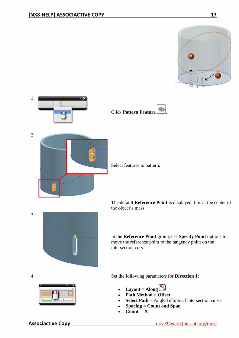
1.
Click Pattern Feature .
2.
Select features to pattern.
The default Reference Point is displayed. It is at the center of
the object’s mass.
3.
In the Reference Point group, use Specify Point options to
move the reference point to the tangency point on the
intersection curve.
4.
Set the following parameters for Direction 1:
Layout = Along
Path Method = Offset
Select Path = Angled elliptical intersection curve
Spacing = Count and Span
Count = 20
[NX8-HELP] ASSOCIACTIVE COPY 18
Associactive Copy drive24ward (meslab.org/mes)
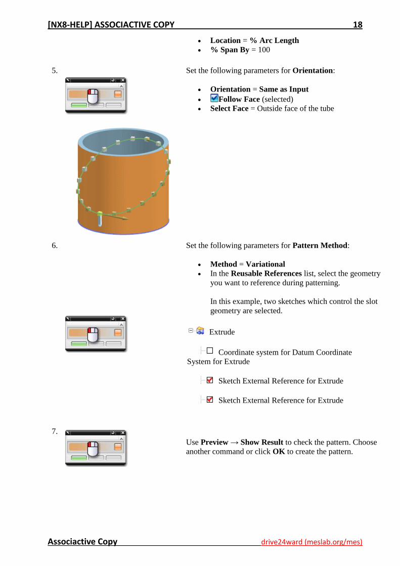
Location = % Arc Length
% Span By = 100
5.
Set the following parameters for Orientation:
Orientation = Same as Input
Follow Face (selected)
Select Face = Outside face of the tube
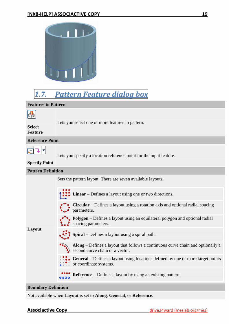
6.
Set the following parameters for Pattern Method:
Method = Variational
In the Reusable References list, select the geometry
you want to reference during patterning.
In this example, two sketches which control the slot
geometry are selected.
Extrude
Coordinate system for Datum Coordinate
System for Extrude
Sketch External Reference for Extrude
Sketch External Reference for Extrude
7.
Use Preview → Show Result to check the pattern. Choose
another command or click OK to create the pattern.
[NX8-HELP] ASSOCIACTIVE COPY 19
Associactive Copy drive24ward (meslab.org/mes)
1.7. Pattern Feature dialog box Features to Pattern
Select
Feature
Lets you select one or more features to pattern.
Reference Point
Specify Point
Lets you specify a location reference point for the input feature.
Pattern Definition
Layout
Sets the pattern layout. There are seven available layouts.
Linear – Defines a layout using one or two directions.
Circular – Defines a layout using a rotation axis and optional radial spacing
parameters.
Polygon – Defines a layout using an equilateral polygon and optional radial
spacing parameters.
Spiral – Defines a layout using a spiral path.
Along – Defines a layout that follows a continuous curve chain and optionally a
second curve chain or a vector.
General – Defines a layout using locations defined by one or more target points
or coordinate systems.
Reference – Defines a layout by using an existing pattern.
Boundary Definition
Not available when Layout is set to Along, General, or Reference.
[NX8-HELP] ASSOCIACTIVE COPY 20
Associactive Copy drive24ward (meslab.org/mes)
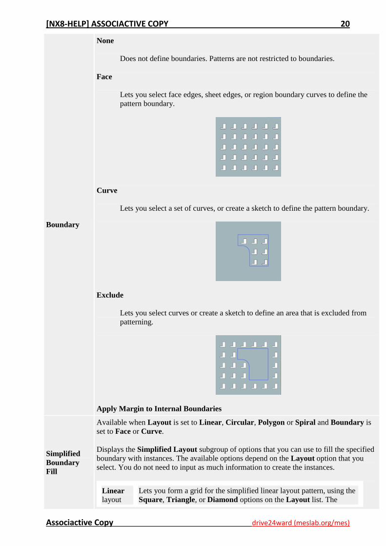
Boundary
None
Does not define boundaries. Patterns are not restricted to boundaries.
Face
Lets you select face edges, sheet edges, or region boundary curves to define the
pattern boundary.
Curve
Lets you select a set of curves, or create a sketch to define the pattern boundary.
Exclude
Lets you select curves or create a sketch to define an area that is excluded from
patterning.
Apply Margin to Internal Boundaries
Simplified
Boundary
Fill
Available when Layout is set to Linear, Circular, Polygon or Spiral and Boundary is
set to Face or Curve.
Displays the Simplified Layout subgroup of options that you can use to fill the specified
boundary with instances. The available options depend on the Layout option that you
select. You do not need to input as much information to create the instances.
Linear layout
Lets you form a grid for the simplified linear layout pattern, using the
Square, Triangle, or Diamond options on the Layout list. The
[NX8-HELP] ASSOCIACTIVE COPY 21
Associactive Copy drive24ward (meslab.org/mes)
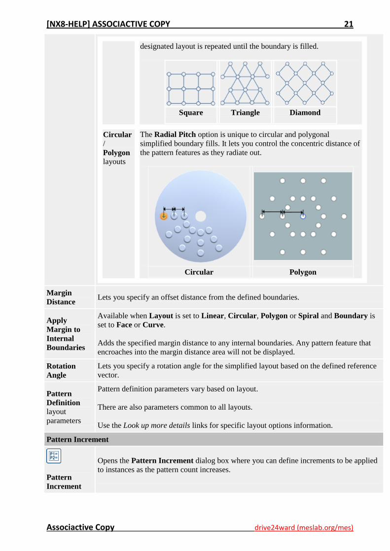
designated layout is repeated until the boundary is filled.
Square Triangle Diamond
Circular /
Polygon layouts
The Radial Pitch option is unique to circular and polygonal
simplified boundary fills. It lets you control the concentric distance of
the pattern features as they radiate out.
Circular
Polygon
Margin
Distance Lets you specify an offset distance from the defined boundaries.
Apply
Margin to
Internal
Boundaries
Available when Layout is set to Linear, Circular, Polygon or Spiral and Boundary is
set to Face or Curve.
Adds the specified margin distance to any internal boundaries. Any pattern feature that
encroaches into the margin distance area will not be displayed.
Rotation
Angle
Lets you specify a rotation angle for the simplified layout based on the defined reference
vector.
Pattern
Definition layout
parameters
Pattern definition parameters vary based on layout.
There are also parameters common to all layouts.
Use the Look up more details links for specific layout options information.
Pattern Increment
Pattern
Increment
Opens the Pattern Increment dialog box where you can define increments to be applied
to instances as the pattern count increases.
[NX8-HELP] ASSOCIACTIVE COPY 22
Associactive Copy drive24ward (meslab.org/mes)
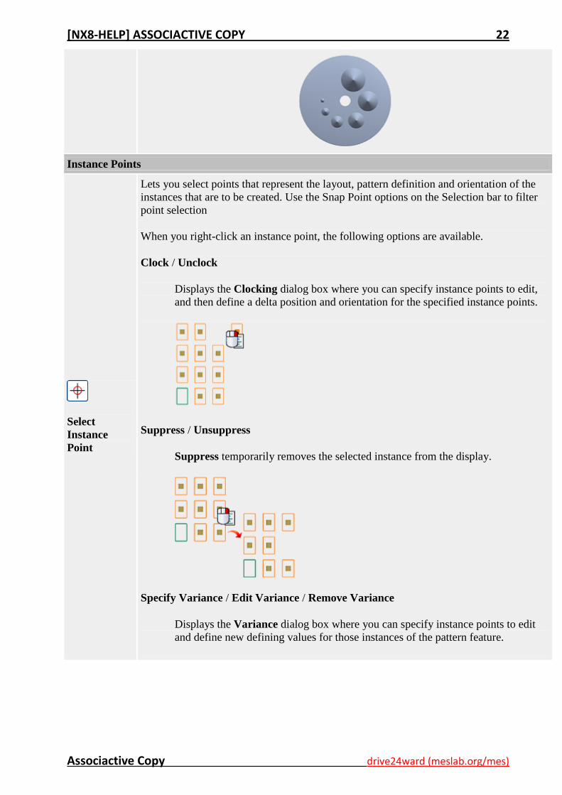
Instance Points
Select
Instance
Point
Lets you select points that represent the layout, pattern definition and orientation of the
instances that are to be created. Use the Snap Point options on the Selection bar to filter
point selection
When you right-click an instance point, the following options are available.
Clock / Unclock
Displays the Clocking dialog box where you can specify instance points to edit,
and then define a delta position and orientation for the specified instance points.
Suppress / Unsuppress
Suppress temporarily removes the selected instance from the display.
Specify Variance / Edit Variance / Remove Variance
Displays the Variance dialog box where you can specify instance points to edit
and define new defining values for those instances of the pattern feature.
[NX8-HELP] ASSOCIACTIVE COPY 23
Associactive Copy drive24ward (meslab.org/mes)
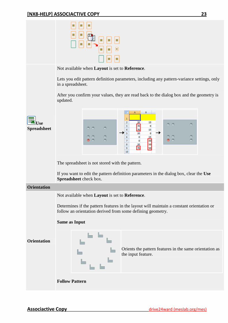
Use
Spreadsheet
Not available when Layout is set to Reference.
Lets you edit pattern definition parameters, including any pattern-variance settings, only
in a spreadsheet.
After you confirm your values, they are read back to the dialog box and the geometry is
updated.
The spreadsheet is not stored with the pattern.
If you want to edit the pattern definition parameters in the dialog box, clear the Use
Spreadsheet check box.
Orientation
Orientation
Not available when Layout is set to Reference.
Determines if the pattern features in the layout will maintain a constant orientation or
follow an orientation derived from some defining geometry.
Same as Input
Orients the pattern features in the same orientation as
the input feature.
Follow Pattern
[NX8-HELP] ASSOCIACTIVE COPY 24
Associactive Copy drive24ward (meslab.org/mes)
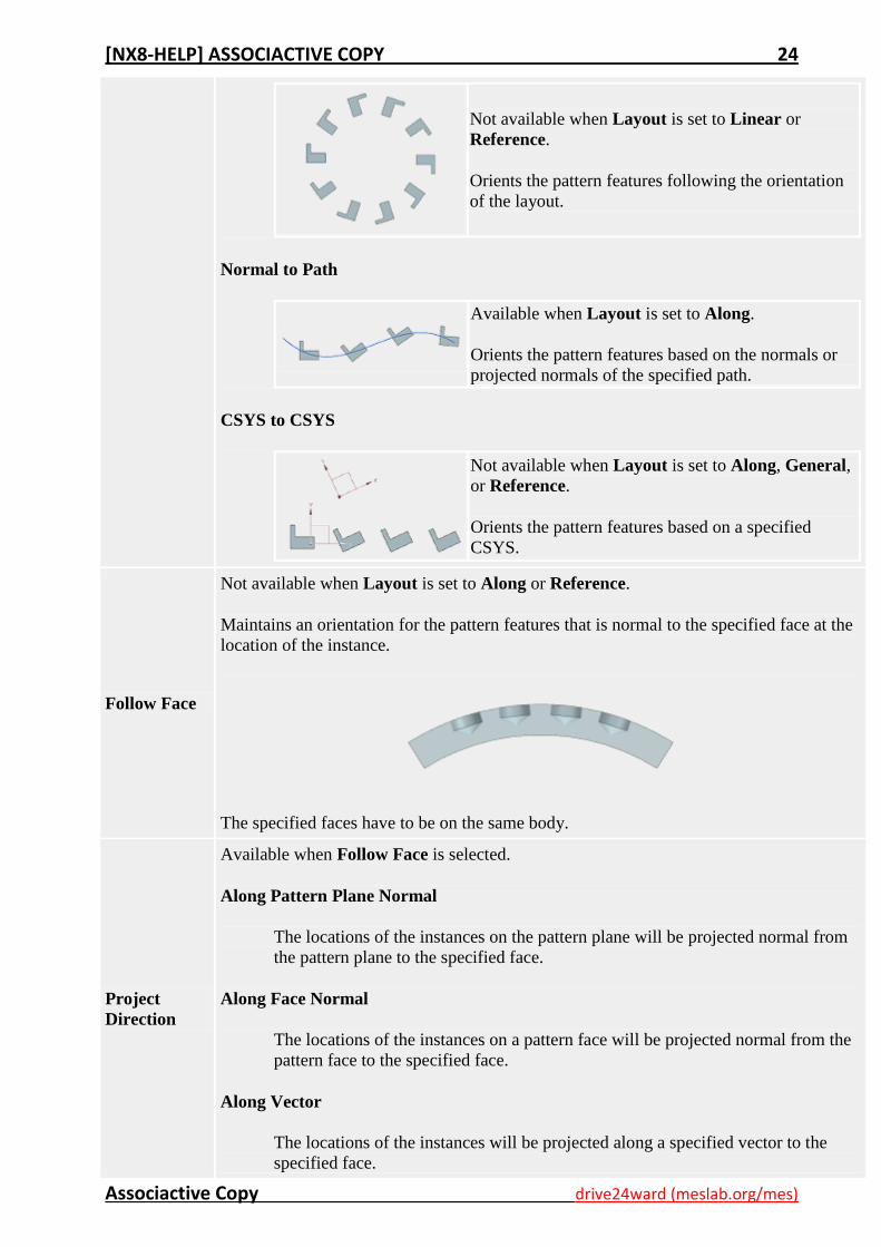
Not available when Layout is set to Linear or
Reference.
Orients the pattern features following the orientation
of the layout.
Normal to Path
Available when Layout is set to Along.
Orients the pattern features based on the normals or
projected normals of the specified path.
CSYS to CSYS
Not available when Layout is set to Along, General,
or Reference.
Orients the pattern features based on a specified
CSYS.
Follow Face
Not available when Layout is set to Along or Reference.
Maintains an orientation for the pattern features that is normal to the specified face at the
location of the instance.
The specified faces have to be on the same body.
Project
Direction
Available when Follow Face is selected.
Along Pattern Plane Normal
The locations of the instances on the pattern plane will be projected normal from
the pattern plane to the specified face.
Along Face Normal
The locations of the instances on a pattern face will be projected normal from the
pattern face to the specified face.
Along Vector
The locations of the instances will be projected along a specified vector to the
specified face.
[NX8-HELP] ASSOCIACTIVE COPY 25
Associactive Copy drive24ward (meslab.org/mes)
Pattern Settings
Available when Layout is set to Linear, Circular or Along.
Pattern Method
Method
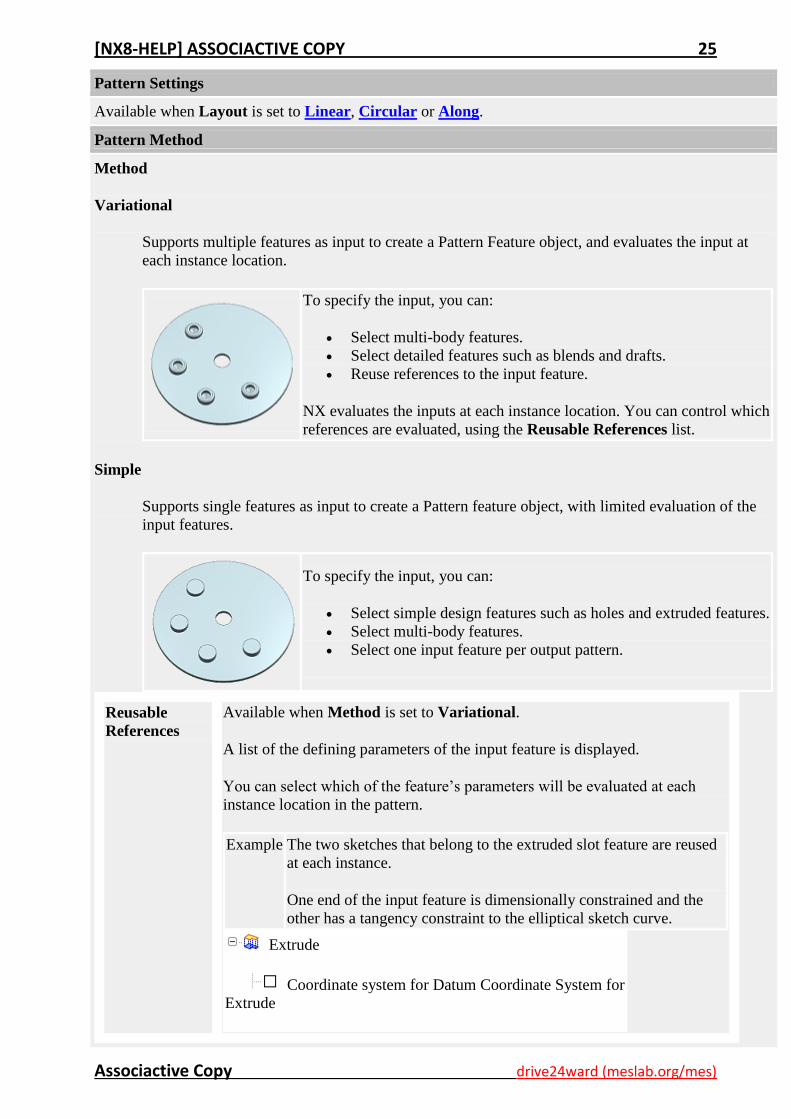
Variational
Supports multiple features as input to create a Pattern Feature object, and evaluates the input at
each instance location.
To specify the input, you can:
Select multi-body features.
Select detailed features such as blends and drafts.
Reuse references to the input feature.
NX evaluates the inputs at each instance location. You can control which
references are evaluated, using the Reusable References list.
Simple
Supports single features as input to create a Pattern feature object, with limited evaluation of the
input features.
To specify the input, you can:
Select simple design features such as holes and extruded features.
Select multi-body features.
Select one input feature per output pattern.
Reusable
References
Available when Method is set to Variational.
A list of the defining parameters of the input feature is displayed.
You can select which of the feature’s parameters will be evaluated at each
instance location in the pattern.
Example The two sketches that belong to the extruded slot feature are reused
at each instance.
One end of the input feature is dimensionally constrained and the
other has a tangency constraint to the elliptical sketch curve.
Extrude
Coordinate system for Datum Coordinate System for
Extrude
[NX8-HELP] ASSOCIACTIVE COPY 26
Associactive Copy drive24ward (meslab.org/mes)
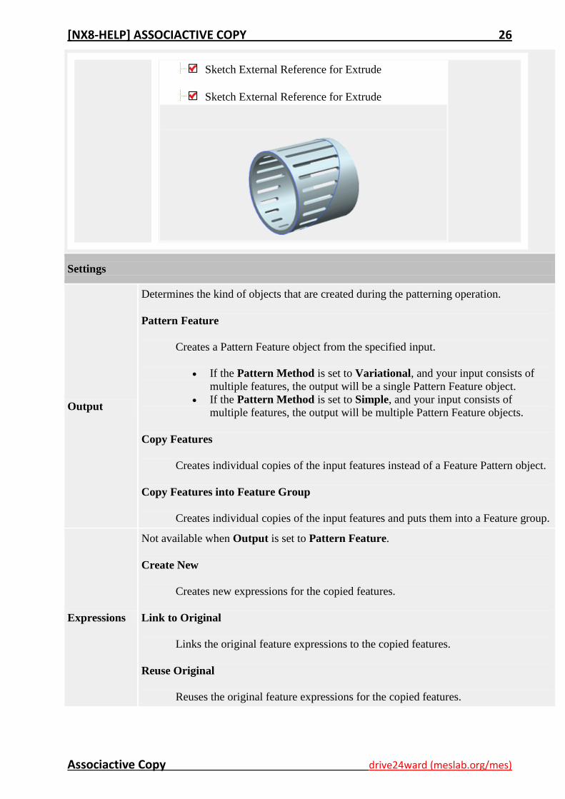
Sketch External Reference for Extrude
Sketch External Reference for Extrude
Settings
Output
Determines the kind of objects that are created during the patterning operation.
Pattern Feature
Creates a Pattern Feature object from the specified input.
If the Pattern Method is set to Variational, and your input consists of
multiple features, the output will be a single Pattern Feature object.
If the Pattern Method is set to Simple, and your input consists of
multiple features, the output will be multiple Pattern Feature objects.
Copy Features
Creates individual copies of the input features instead of a Feature Pattern object.
Copy Features into Feature Group
Creates individual copies of the input features and puts them into a Feature group.
Expressions
Not available when Output is set to Pattern Feature.
Create New
Creates new expressions for the copied features.
Link to Original
Links the original feature expressions to the copied features.
Reuse Original
Reuses the original feature expressions for the copied features.
[NX8-HELP] ASSOCIACTIVE COPY 27
Associactive Copy drive24ward (meslab.org/mes)
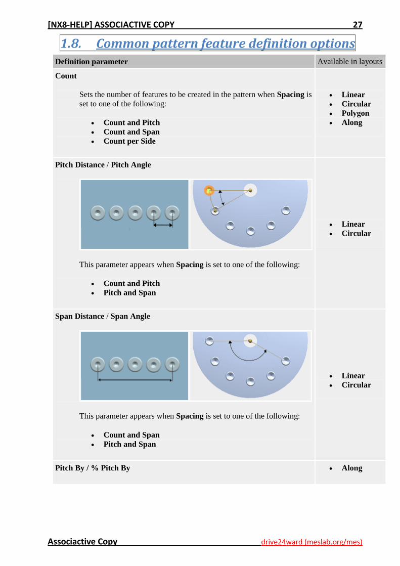
1.8. Common pattern feature definition options Definition parameter Available in layouts
Count
Sets the number of features to be created in the pattern when Spacing is
set to one of the following:
Count and Pitch
Count and Span
Count per Side
Linear
Circular
Polygon
Along
Pitch Distance / Pitch Angle
This parameter appears when Spacing is set to one of the following:
Count and Pitch
Pitch and Span
Linear
Circular
Span Distance / Span Angle
This parameter appears when Spacing is set to one of the following:
Count and Span
Pitch and Span
Linear
Circular
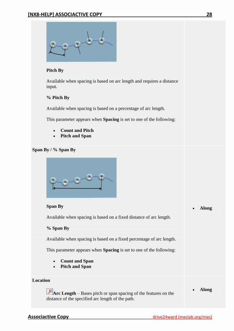
Pitch By / % Pitch By Along
[NX8-HELP] ASSOCIACTIVE COPY 28
Associactive Copy drive24ward (meslab.org/mes)
Pitch By
Available when spacing is based on arc length and requires a distance
input.
% Pitch By
Available when spacing is based on a percentage of arc length.
This parameter appears when Spacing is set to one of the following:
Count and Pitch
Pitch and Span
Span By / % Span By
Span By
Available when spacing is based on a fixed distance of arc length.
% Span By
Available when spacing is based on a fixed percentage of arc length.
This parameter appears when Spacing is set to one of the following:
Count and Span
Pitch and Span
Along
Location
Arc Length – Bases pitch or span spacing of the features on the
distance of the specified arc length of the path.
Along
[NX8-HELP] ASSOCIACTIVE COPY 29
Associactive Copy drive24ward (meslab.org/mes)
% Arc Length – Bases pitch or span spacing of the features on the
percentage of the specified arc length of the path.
This parameter appears when Spacing is set to one of the following:
Count and Pitch
Count and Span
Pitch and Span
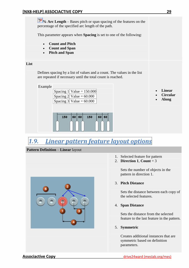
List
Defines spacing by a list of values and a count. The values in the list
are repeated if necessary until the total count is reached.
Example
Spacing 1 Value = 150.000
Spacing 2 Value = 60.000
Spacing 3 Value = 60.000
Linear
Circular
Along
1.9. Linear pattern feature layout options Pattern Definition – Linear layout
1. Selected feature for pattern
2. Direction 1, Count = 3
Sets the number of objects in the
pattern in direction 1.
3. Pitch Distance
Sets the distance between each copy of
the selected features.
4. Span Distance
Sets the distance from the selected
feature to the last feature in the pattern.
5. Symmetric
Creates additional instances that are
symmetric based on definition
parameters.
[NX8-HELP] ASSOCIACTIVE COPY 30
Associactive Copy drive24ward (meslab.org/mes)
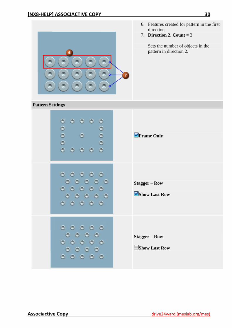
6. Features created for pattern in the first
direction
7. Direction 2, Count = 3
Sets the number of objects in the
pattern in direction 2.
Pattern Settings
Frame Only
Stagger – Row
Show Last Row
Stagger – Row
Show Last Row
[NX8-HELP] ASSOCIACTIVE COPY 31
Associactive Copy drive24ward (meslab.org/mes)
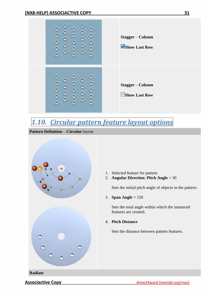
Stagger – Column
Show Last Row
Stagger – Column
Show Last Row
1.10. Circular pattern feature layout options Pattern Definition – Circular layout
1. Selected feature for pattern
2. Angular Direction: Pitch Angle = 30
Sets the initial pitch angle of objects in the pattern.
3. Span Angle = 150
Sets the total angle within which the instanced
features are created.
4. Pitch Distance
Sets the distance between pattern features.
Radiate
[NX8-HELP] ASSOCIACTIVE COPY 32
Associactive Copy drive24ward (meslab.org/mes)
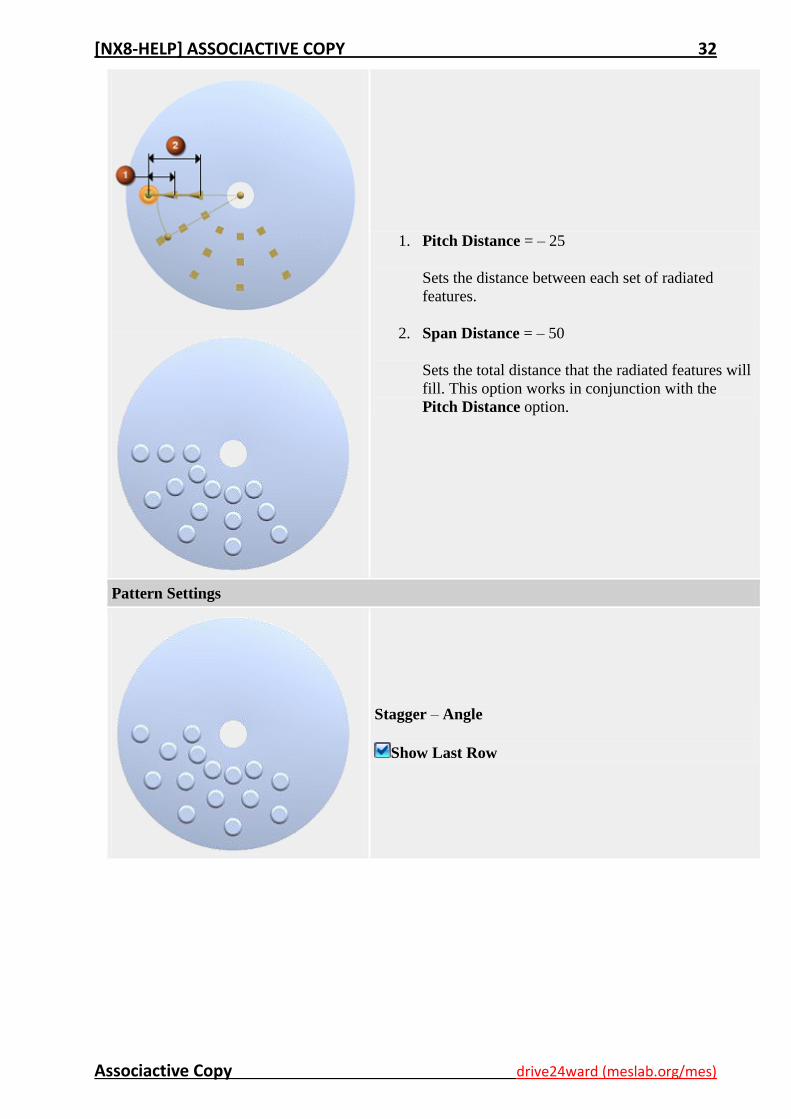
1. Pitch Distance = – 25
Sets the distance between each set of radiated
features.
2. Span Distance = – 50
Sets the total distance that the radiated features will
fill. This option works in conjunction with the
Pitch Distance option.
Pattern Settings
Stagger – Angle
Show Last Row
[NX8-HELP] ASSOCIACTIVE COPY 33
Associactive Copy drive24ward (meslab.org/mes)
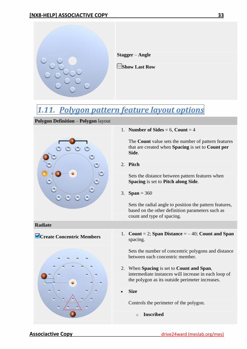
Stagger – Angle
Show Last Row
1.11. Polygon pattern feature layout options Polygon Definition – Polygon layout
1. Number of Sides = 6, Count = 4
The Count value sets the number of pattern features
that are created when Spacing is set to Count per
Side.
2. Pitch
Sets the distance between pattern features when
Spacing is set to Pitch along Side.
3. Span = 360
Sets the radial angle to position the pattern features,
based on the other definition parameters such as
count and type of spacing.
Radiate
Create Concentric Members
1. Count = 2; Span Distance = – 40; Count and Span
spacing.
Sets the number of concentric polygons and distance
between each concentric member.
2. When Spacing is set to Count and Span,
intermediate instances will increase in each loop of
the polygon as its outside perimeter increases.
Size
Controls the perimeter of the polygon.
o Inscribed
[NX8-HELP] ASSOCIACTIVE COPY 34
Associactive Copy drive24ward (meslab.org/mes)
(Default) Locates polygon reference points
inside the defined polygon.
o Circumscribed
Locates polygon reference points outside the
defined polygon.
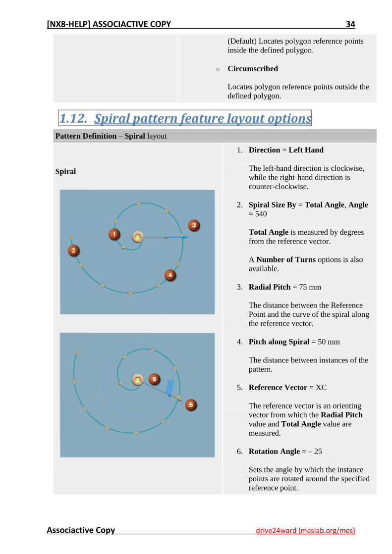
1.12. Spiral pattern feature layout options Pattern Definition – Spiral layout
Spiral
1. Direction = Left Hand
The left-hand direction is clockwise,
while the right-hand direction is
counter-clockwise.
2. Spiral Size By = Total Angle, Angle
= 540
Total Angle is measured by degrees
from the reference vector.
A Number of Turns options is also
available.
3. Radial Pitch = 75 mm
The distance between the Reference
Point and the curve of the spiral along
the reference vector.
4. Pitch along Spiral = 50 mm
The distance between instances of the
pattern.
5. Reference Vector = XC
The reference vector is an orienting
vector from which the Radial Pitch
value and Total Angle value are
measured.
6. Rotation Angle = – 25
Sets the angle by which the instance
points are rotated around the specified
reference point.
[NX8-HELP] ASSOCIACTIVE COPY 35
Associactive Copy drive24ward (meslab.org/mes)
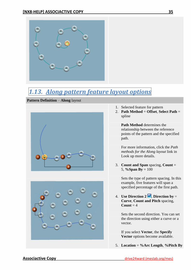
1.13. Along pattern feature layout options Pattern Definition – Along layout
1. Selected feature for pattern
2. Path Method = Offset, Select Path =
spline
Path Method determines the
relationship between the reference
points of the pattern and the specified
path.
For more information, click the Path
methods for the Along layout link in
Look up more details.
3. Count and Span spacing, Count =
5, %Span By = 100
Sets the type of pattern spacing. In this
example, five features will span a
specified percentage of the first path.
4. Use Direction 2 , Direction by =
Curve, Count and Pitch spacing,
Count = 4
Sets the second direction. You can set
the direction using either a curve or a
vector.
If you select Vector, the Specify
Vector options become available.
5. Location = %Arc Length, %Pitch By
[NX8-HELP] ASSOCIACTIVE COPY 36
Associactive Copy drive24ward (meslab.org/mes)
= 33
Sets the location of the features based
on percentage of arc length.
The location of each feature on the
specified arc length is determined by
the specified pitch percentage.
Pattern Settings
Input Feature Only for Direction 2
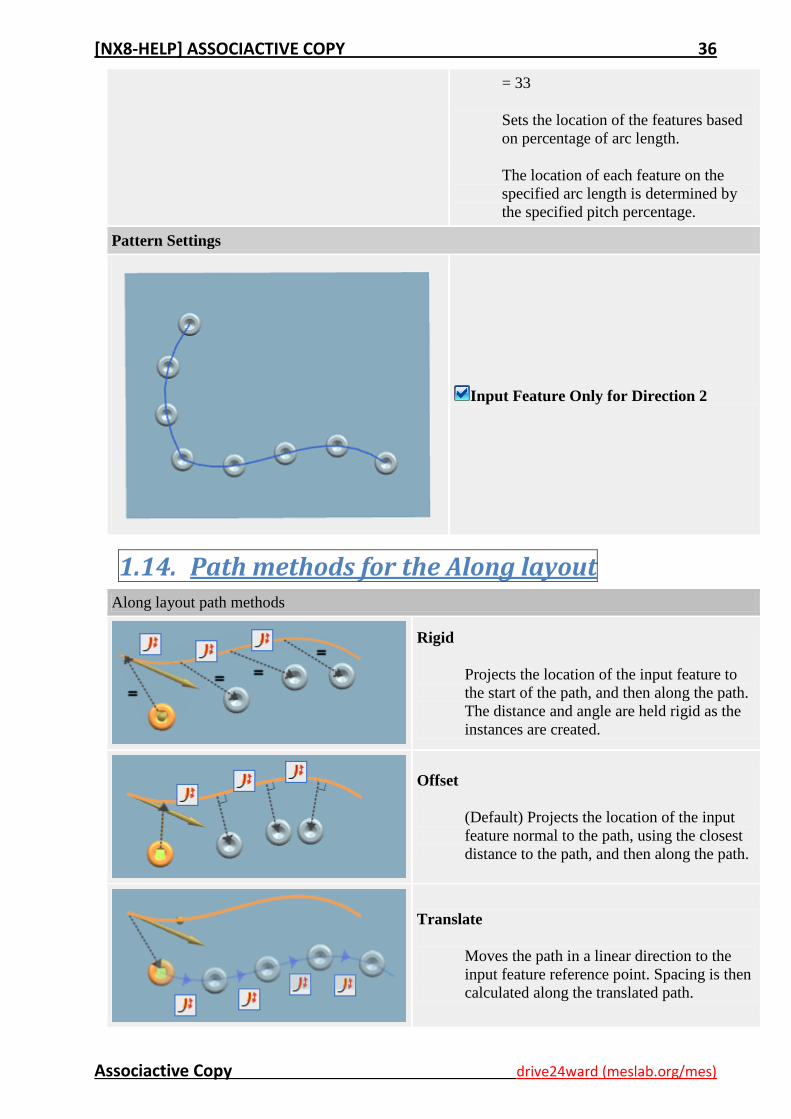
1.14. Path methods for the Along layout Along layout path methods
Rigid
Projects the location of the input feature to
the start of the path, and then along the path.
The distance and angle are held rigid as the
instances are created.
Offset
(Default) Projects the location of the input
feature normal to the path, using the closest
distance to the path, and then along the path.
Translate
Moves the path in a linear direction to the
input feature reference point. Spacing is then
calculated along the translated path.
[NX8-HELP] ASSOCIACTIVE COPY 37
Associactive Copy drive24ward (meslab.org/mes)
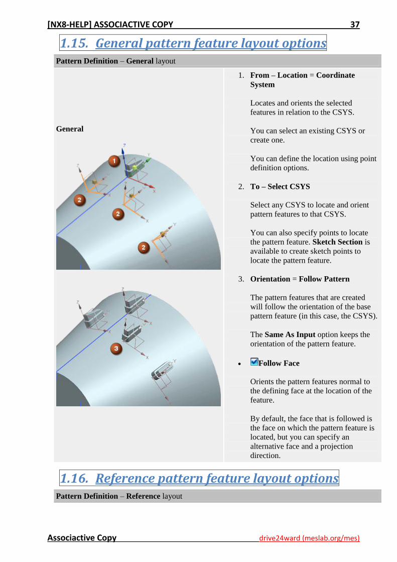
1.15. General pattern feature layout options Pattern Definition – General layout
General
1. From – Location = Coordinate
System
Locates and orients the selected
features in relation to the CSYS.
You can select an existing CSYS or
create one.
You can define the location using point
definition options.
2. To – Select CSYS
Select any CSYS to locate and orient
pattern features to that CSYS.
You can also specify points to locate
the pattern feature. Sketch Section is
available to create sketch points to
locate the pattern feature.
3. Orientation = Follow Pattern
The pattern features that are created
will follow the orientation of the base
pattern feature (in this case, the CSYS).
The Same As Input option keeps the
orientation of the pattern feature.
Follow Face
Orients the pattern features normal to
the defining face at the location of the
feature.
By default, the face that is followed is
the face on which the pattern feature is
located, but you can specify an
alternative face and a projection
direction.
1.16. Reference pattern feature layout options Pattern Definition – Reference layout
[NX8-HELP] ASSOCIACTIVE COPY 38
Associactive Copy drive24ward (meslab.org/mes)
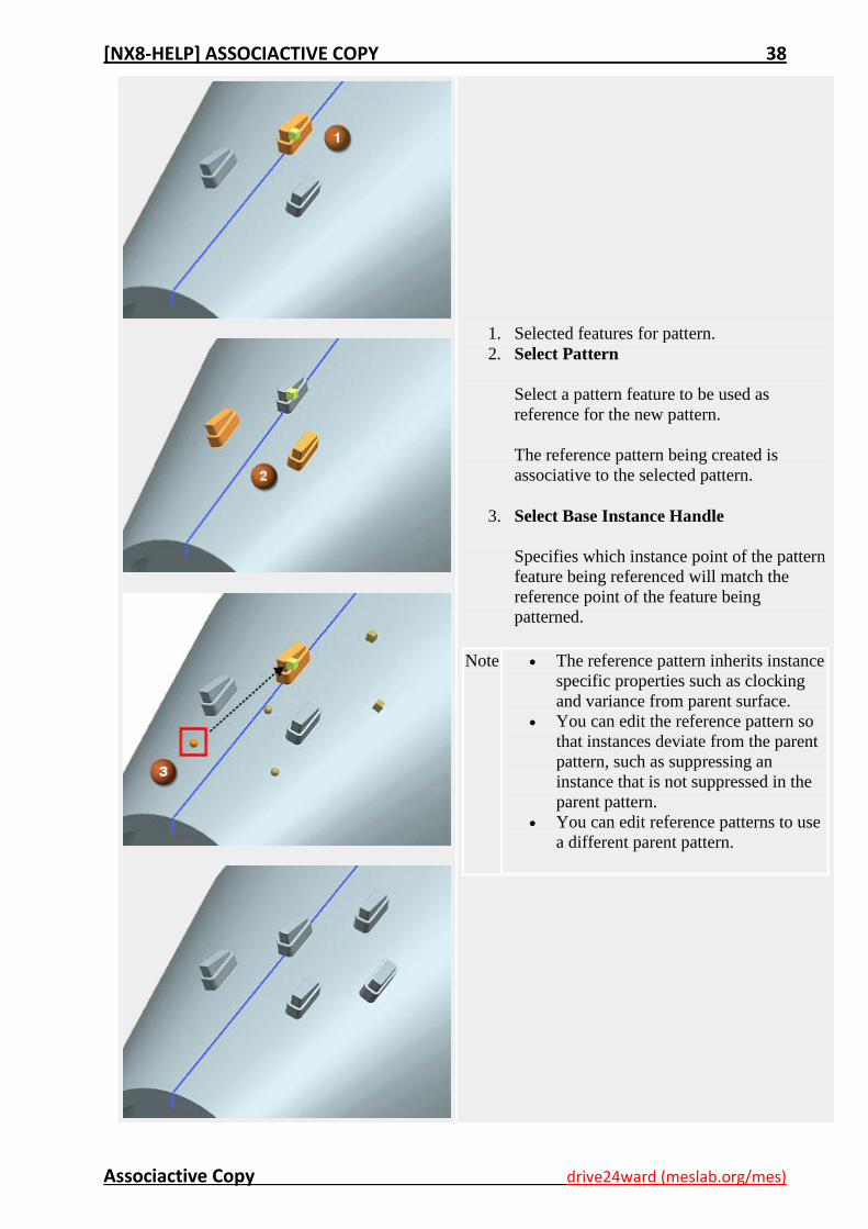
1. Selected features for pattern.
2. Select Pattern
Select a pattern feature to be used as
reference for the new pattern.
The reference pattern being created is
associative to the selected pattern.
3. Select Base Instance Handle
Specifies which instance point of the pattern
feature being referenced will match the
reference point of the feature being
patterned.
Note The reference pattern inherits instance
specific properties such as clocking
and variance from parent surface.
You can edit the reference pattern so
that instances deviate from the parent
pattern, such as suppressing an
instance that is not suppressed in the
parent pattern.
You can edit reference patterns to use
a different parent pattern.
[NX8-HELP] ASSOCIACTIVE COPY 39
Associactive Copy drive24ward (meslab.org/mes)
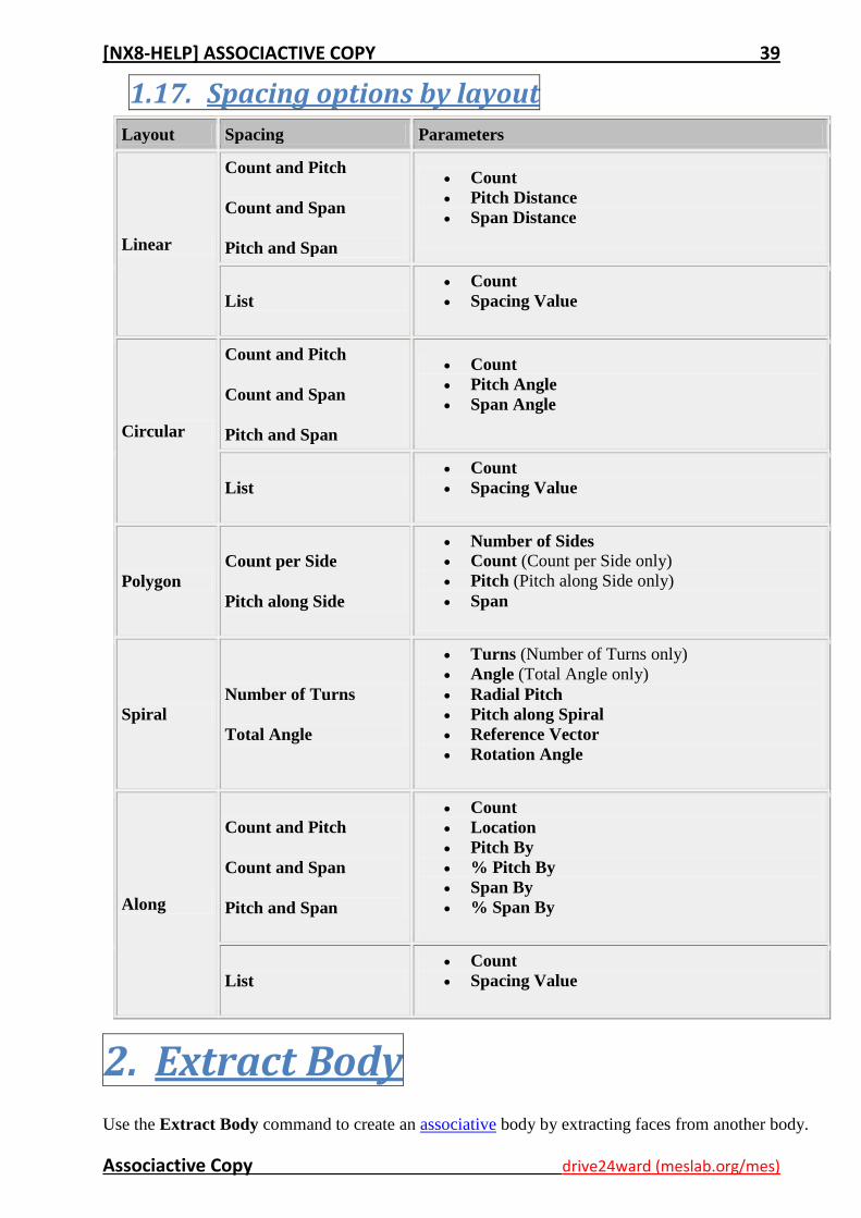
1.17. Spacing options by layout
Layout Spacing Parameters
Linear
Count and Pitch
Count and Span
Pitch and Span
Count
Pitch Distance
Span Distance
List
Count
Spacing Value
Circular
Count and Pitch
Count and Span
Pitch and Span
Count
Pitch Angle
Span Angle
List
Count
Spacing Value
Polygon
Count per Side
Pitch along Side
Number of Sides Count (Count per Side only)
Pitch (Pitch along Side only)
Span
Spiral
Number of Turns
Total Angle
Turns (Number of Turns only)
Angle (Total Angle only)
Radial Pitch
Pitch along Spiral
Reference Vector
Rotation Angle
Along
Count and Pitch
Count and Span
Pitch and Span
Count
Location
Pitch By
% Pitch By
Span By
% Span By
List
Count
Spacing Value
2. Extract Body Use the Extract Body command to create an associative body by extracting faces from another body.
[NX8-HELP] ASSOCIACTIVE COPY 40
Associactive Copy drive24ward (meslab.org/mes)
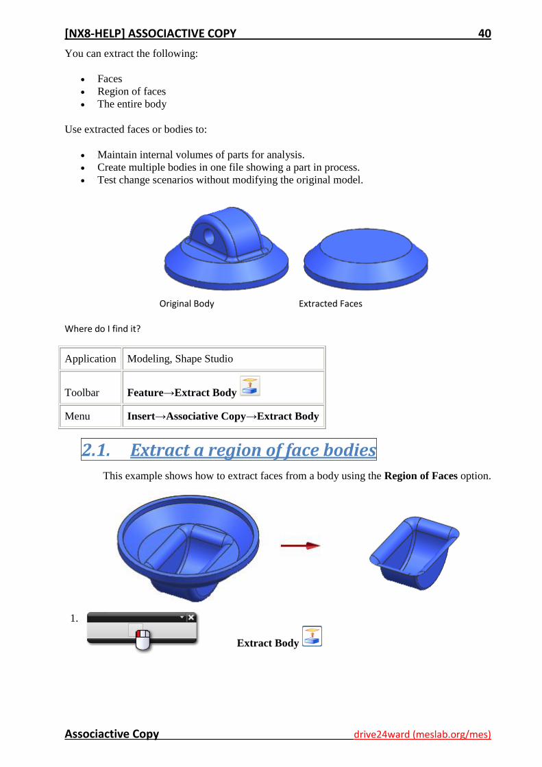
You can extract the following:
Faces
Region of faces
The entire body
Use extracted faces or bodies to:
Maintain internal volumes of parts for analysis.
Create multiple bodies in one file showing a part in process.
Test change scenarios without modifying the original model.
Original Body
Extracted Faces
Where do I find it?
Application Modeling, Shape Studio
Toolbar Feature→Extract Body
Menu Insert→Associative Copy→Extract Body
2.1. Extract a region of face bodies
This example shows how to extract faces from a body using the Region of Faces option.
1.
Extract Body
[NX8-HELP] ASSOCIACTIVE COPY 41
Associactive Copy drive24ward (meslab.org/mes)
2.
In the Extract Body dialog box, under Type click Region of
Faces.
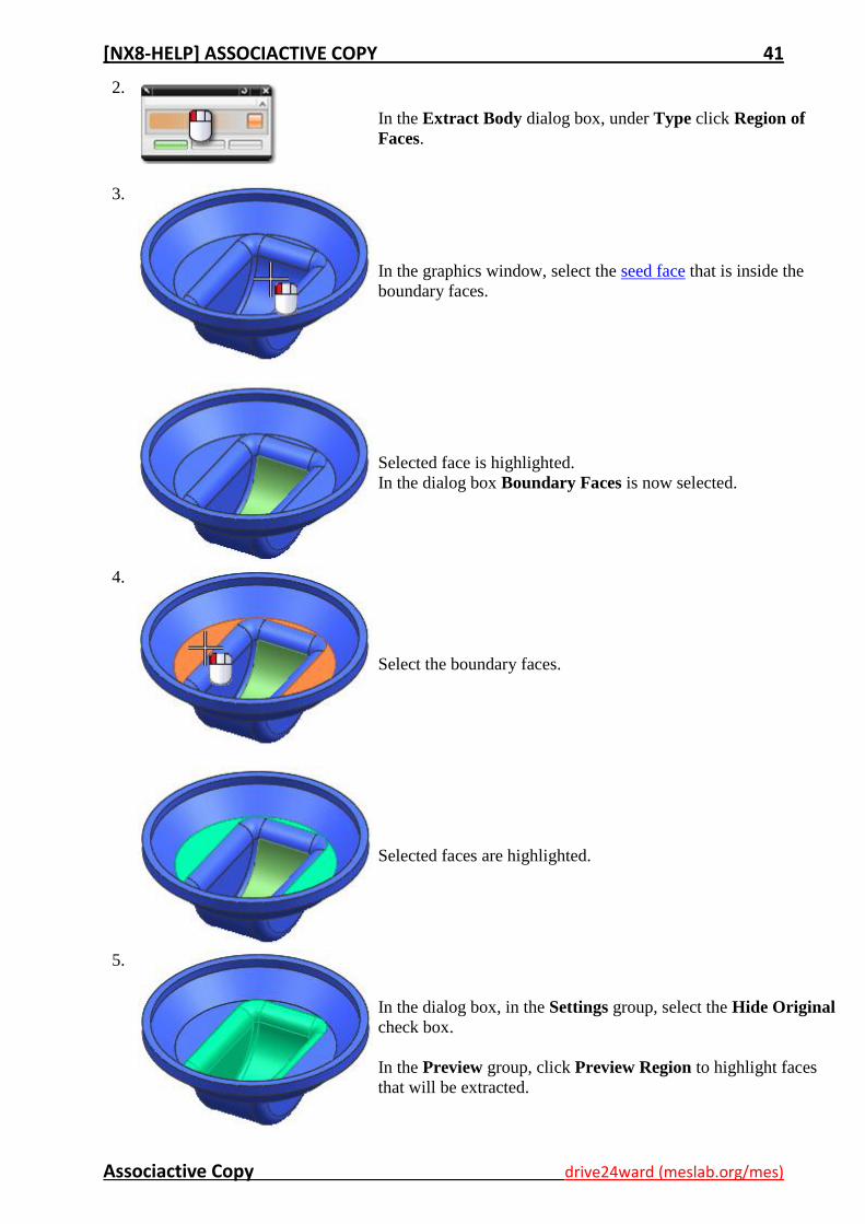
3.
In the graphics window, select the seed face that is inside the
boundary faces.
Selected face is highlighted.
In the dialog box Boundary Faces is now selected.
4.
Select the boundary faces.
Selected faces are highlighted.
5.
In the dialog box, in the Settings group, select the Hide Original
check box.
In the Preview group, click Preview Region to highlight faces
that will be extracted.
[NX8-HELP] ASSOCIACTIVE COPY 42
Associactive Copy drive24ward (meslab.org/mes)
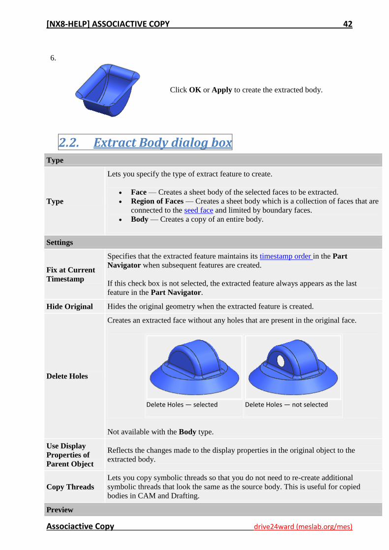
6.
Click OK or Apply to create the extracted body.
2.2. Extract Body dialog box Type
Type
Lets you specify the type of extract feature to create.
Face — Creates a sheet body of the selected faces to be extracted.
Region of Faces — Creates a sheet body which is a collection of faces that are
connected to the seed face and limited by boundary faces.
Body — Creates a copy of an entire body.
Settings
Fix at Current
Timestamp
Specifies that the extracted feature maintains its timestamp order in the Part
Navigator when subsequent features are created.
If this check box is not selected, the extracted feature always appears as the last
feature in the Part Navigator.
Hide Original Hides the original geometry when the extracted feature is created.
Delete Holes
Creates an extracted face without any holes that are present in the original face.
Delete Holes — selected
Delete Holes — not selected
Not available with the Body type.
Use Display
Properties of
Parent Object
Reflects the changes made to the display properties in the original object to the
extracted body.
Copy Threads
Lets you copy symbolic threads so that you do not need to re-create additional
symbolic threads that look the same as the source body. This is useful for copied
bodies in CAM and Drafting.
Preview
[NX8-HELP] ASSOCIACTIVE COPY 43
Associactive Copy drive24ward (meslab.org/mes)
Appears only when Type is set to Region of Faces.
Preview Region
Finished
Preview
Preview Region shows a preview of the resulting extracted region feature after you
have selected the faces.
Finished Preview closes the preview of the extracted region of faces.
Note The options below appear only when Type is set to Region of Faces
Seed Face
Select Face
Lets you select a face contained or inside the boundary faces.
Boundary Faces
Select Face
Lets you select the faces that contain or encircle the seed face.
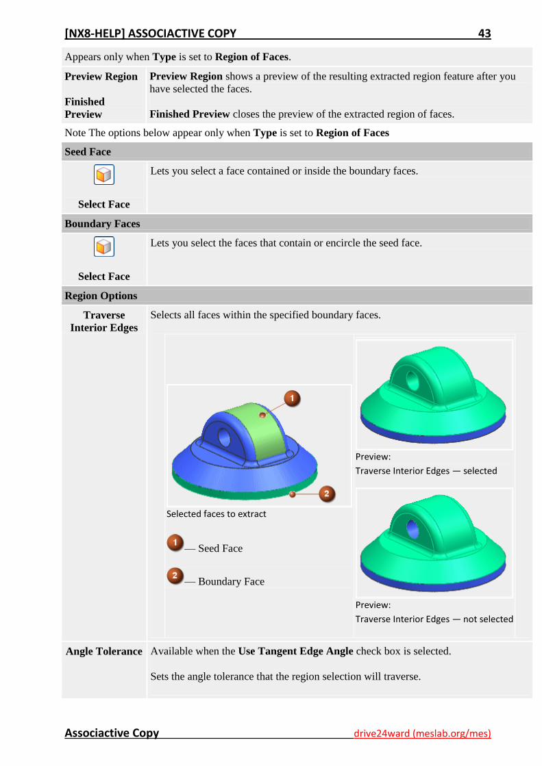
Region Options
Traverse
Interior Edges
Selects all faces within the specified boundary faces.
Selected faces to extract
— Seed Face
— Boundary Face
Preview:
Traverse Interior Edges — selected
Preview:
Traverse Interior Edges — not selected
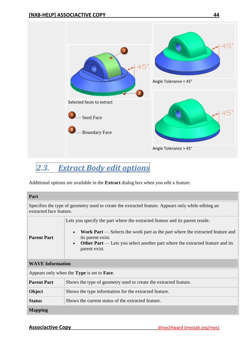
Angle Tolerance Available when the Use Tangent Edge Angle check box is selected.
Sets the angle tolerance that the region selection will traverse.
[NX8-HELP] ASSOCIACTIVE COPY 44
Associactive Copy drive24ward (meslab.org/mes)
Selected faces to extract
— Seed Face
— Boundary Face
Angle Tolerance < 45°
Angle Tolerance > 45°
2.3. Extract Body edit options
Additional options are available in the Extract dialog box when you edit a feature.
Part
Specifies the type of geometry used to create the extracted feature. Appears only while editing an
extracted face feature.
Parent Part
Lets you specify the part where the extracted feature and its parent reside.
Work Part — Selects the work part as the part where the extracted feature and
its parent exist.
Other Part — Lets you select another part where the extracted feature and its
parent exist.
WAVE Information
Appears only when the Type is set to Face.
Parent Part Shows the type of geometry used to create the extracted feature.
Object Shows the type information for the extracted feature.
Status Shows the current status of the extracted feature.
Mapping
[NX8-HELP] ASSOCIACTIVE COPY 45
Associactive Copy drive24ward (meslab.org/mes)
Appears only when the Type is set to Face.
Replacement
Assistant
Opens the Replacement Assistant dialog box to replace the original extracted faces.
Settings
Fix at Current
Timestamp
Lets you change the timestamp at which the extracted feature was created.
If you clear the Fix at Current Timestamp check box, the part is updated, and the
feature is reordered with a later (current) timestamp. If you select this check box, you
can select a timestamp from the list box indicating where the feature should be placed.
This enables you to control how changes made to the original geometry are reflected in
the extracted feature.
Note If you select the tool body of a Boolean feature for extraction or linking when
Fix at Current Timestamp is not selected, the linked body does not reflect any
features that are added to the body resulting from the Boolean. However, if you
extract or link the target body (instead of the tool body), the features resulting
from the Boolean are reflected.
Copy Threads
Lets you copy symbolic threads so that you do not need to re-create additional
symbolic threads that look the same as the source body. This is useful for copied
bodies in CAM and Drafting.
3. Composite Curve
Use the Composite Curve command to extract curves and edges from the work part.
To extract curves and edges from other parts in the same assembly, use the Composite Curve option in
the WAVE Geometry Linker command.
Where do I find it?
Application Modeling
Toolbar Feature→Associative Copy Drop-down→Composite Curve
Menu Insert→Associative Copy→Composite Curve
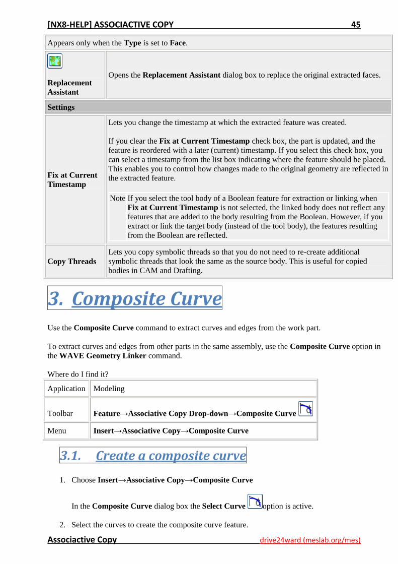
3.1. Create a composite curve
1. Choose Insert→Associative Copy→Composite Curve
In the Composite Curve dialog box the Select Curve option is active.
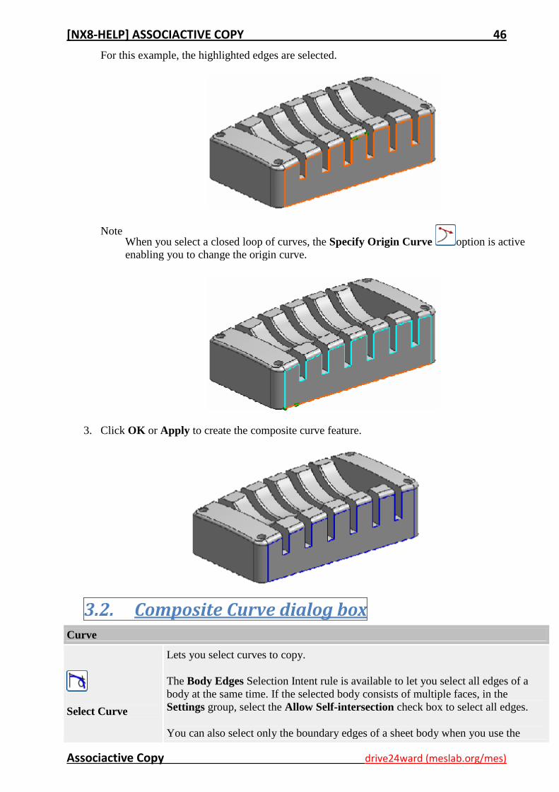
2. Select the curves to create the composite curve feature.
[NX8-HELP] ASSOCIACTIVE COPY 46
Associactive Copy drive24ward (meslab.org/mes)
For this example, the highlighted edges are selected.
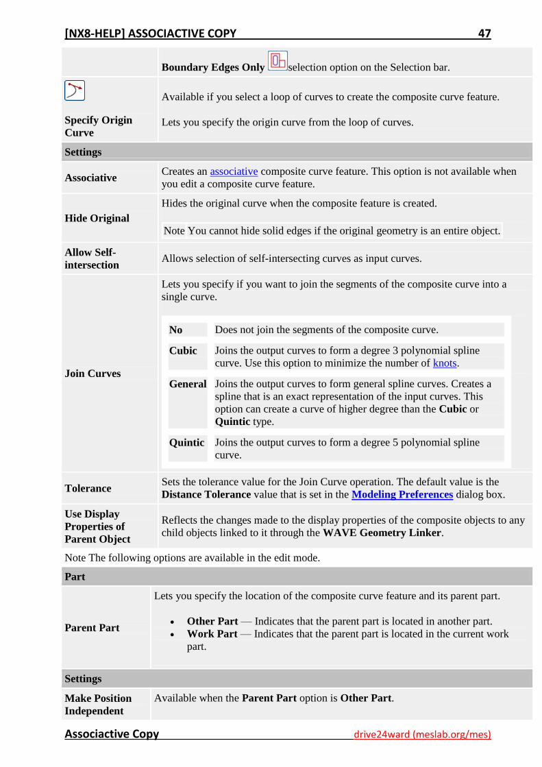
Note When you select a closed loop of curves, the Specify Origin Curve option is active
enabling you to change the origin curve.
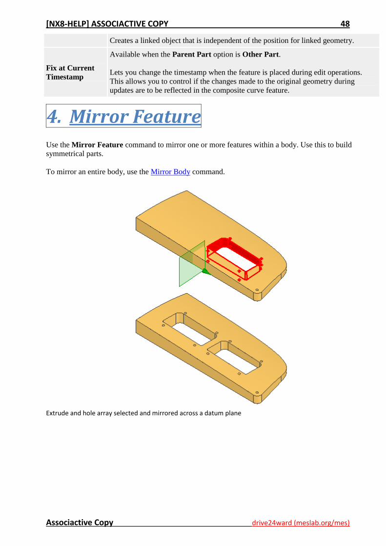
3. Click OK or Apply to create the composite curve feature.
3.2. Composite Curve dialog box Curve
Select Curve
Lets you select curves to copy.
The Body Edges Selection Intent rule is available to let you select all edges of a
body at the same time. If the selected body consists of multiple faces, in the
Settings group, select the Allow Self-intersection check box to select all edges.
You can also select only the boundary edges of a sheet body when you use the
[NX8-HELP] ASSOCIACTIVE COPY 47
Associactive Copy drive24ward (meslab.org/mes)
Boundary Edges Only selection option on the Selection bar.
Specify Origin
Curve
Available if you select a loop of curves to create the composite curve feature.
Lets you specify the origin curve from the loop of curves.
Settings
Associative Creates an associative composite curve feature. This option is not available when
you edit a composite curve feature.
Hide Original
Hides the original curve when the composite feature is created.
Note You cannot hide solid edges if the original geometry is an entire object.
Allow Self-
intersection Allows selection of self-intersecting curves as input curves.
Join Curves
Lets you specify if you want to join the segments of the composite curve into a
single curve.
No Does not join the segments of the composite curve.
Cubic Joins the output curves to form a degree 3 polynomial spline
curve. Use this option to minimize the number of knots.
General Joins the output curves to form general spline curves. Creates a
spline that is an exact representation of the input curves. This
option can create a curve of higher degree than the Cubic or
Quintic type.
Quintic Joins the output curves to form a degree 5 polynomial spline
curve.
Tolerance Sets the tolerance value for the Join Curve operation. The default value is the
Distance Tolerance value that is set in the Modeling Preferences dialog box.
Use Display
Properties of
Parent Object
Reflects the changes made to the display properties of the composite objects to any
child objects linked to it through the WAVE Geometry Linker.
Note The following options are available in the edit mode.
Part
Parent Part
Lets you specify the location of the composite curve feature and its parent part.
Other Part — Indicates that the parent part is located in another part.
Work Part — Indicates that the parent part is located in the current work
part.
Settings
Make Position
Independent
Available when the Parent Part option is Other Part.
[NX8-HELP] ASSOCIACTIVE COPY 48
Associactive Copy drive24ward (meslab.org/mes)
Creates a linked object that is independent of the position for linked geometry.
Fix at Current
Timestamp
Available when the Parent Part option is Other Part.
Lets you change the timestamp when the feature is placed during edit operations.
This allows you to control if the changes made to the original geometry during
updates are to be reflected in the composite curve feature.
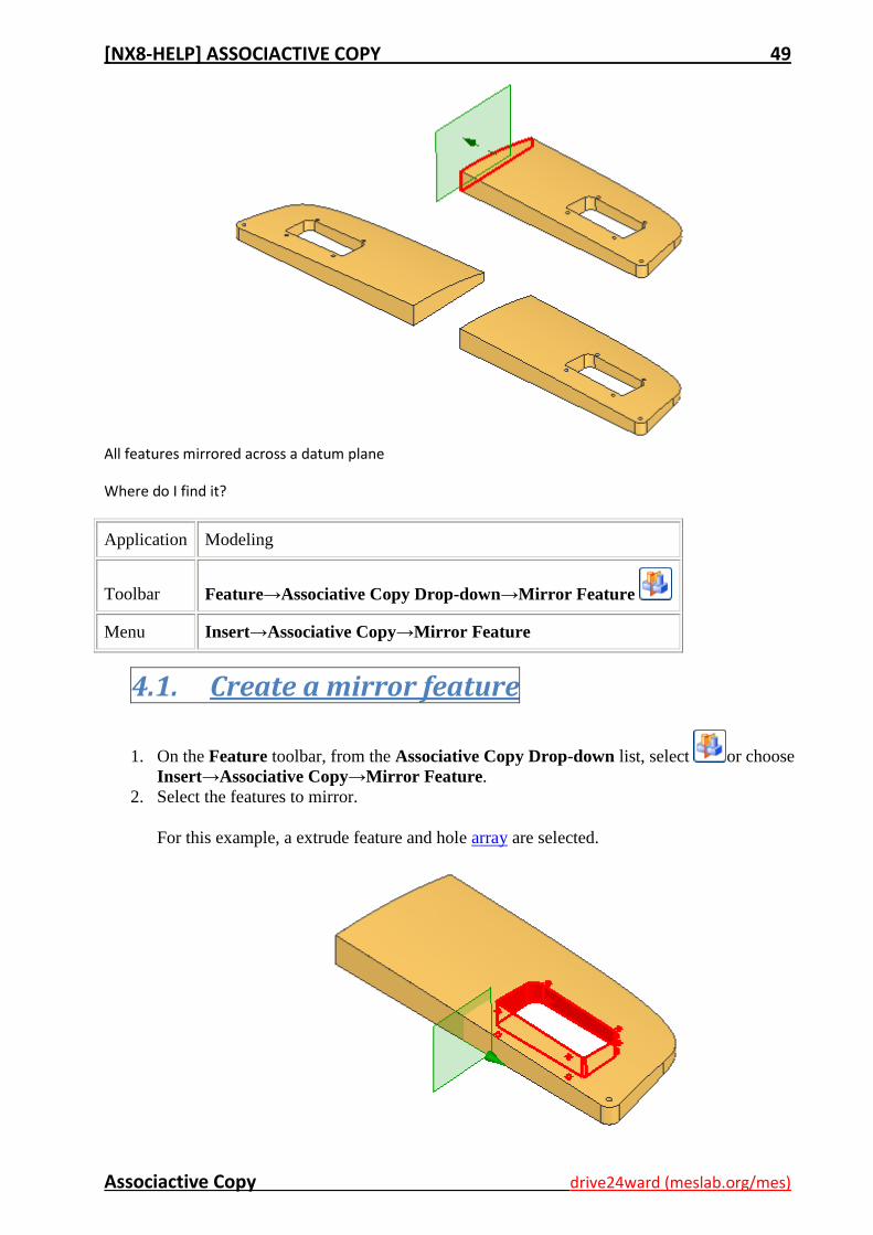
4. Mirror Feature
Use the Mirror Feature command to mirror one or more features within a body. Use this to build
symmetrical parts.
To mirror an entire body, use the Mirror Body command.
Extrude and hole array selected and mirrored across a datum plane
[NX8-HELP] ASSOCIACTIVE COPY 49
Associactive Copy drive24ward (meslab.org/mes)
All features mirrored across a datum plane
Where do I find it?
Application Modeling
Toolbar Feature→Associative Copy Drop-down→Mirror Feature
Menu Insert→Associative Copy→Mirror Feature
4.1. Create a mirror feature
1. On the Feature toolbar, from the Associative Copy Drop-down list, select or choose
Insert→Associative Copy→Mirror Feature.
2. Select the features to mirror.
For this example, a extrude feature and hole array are selected.
[NX8-HELP] ASSOCIACTIVE COPY 50
Associactive Copy drive24ward (meslab.org/mes)
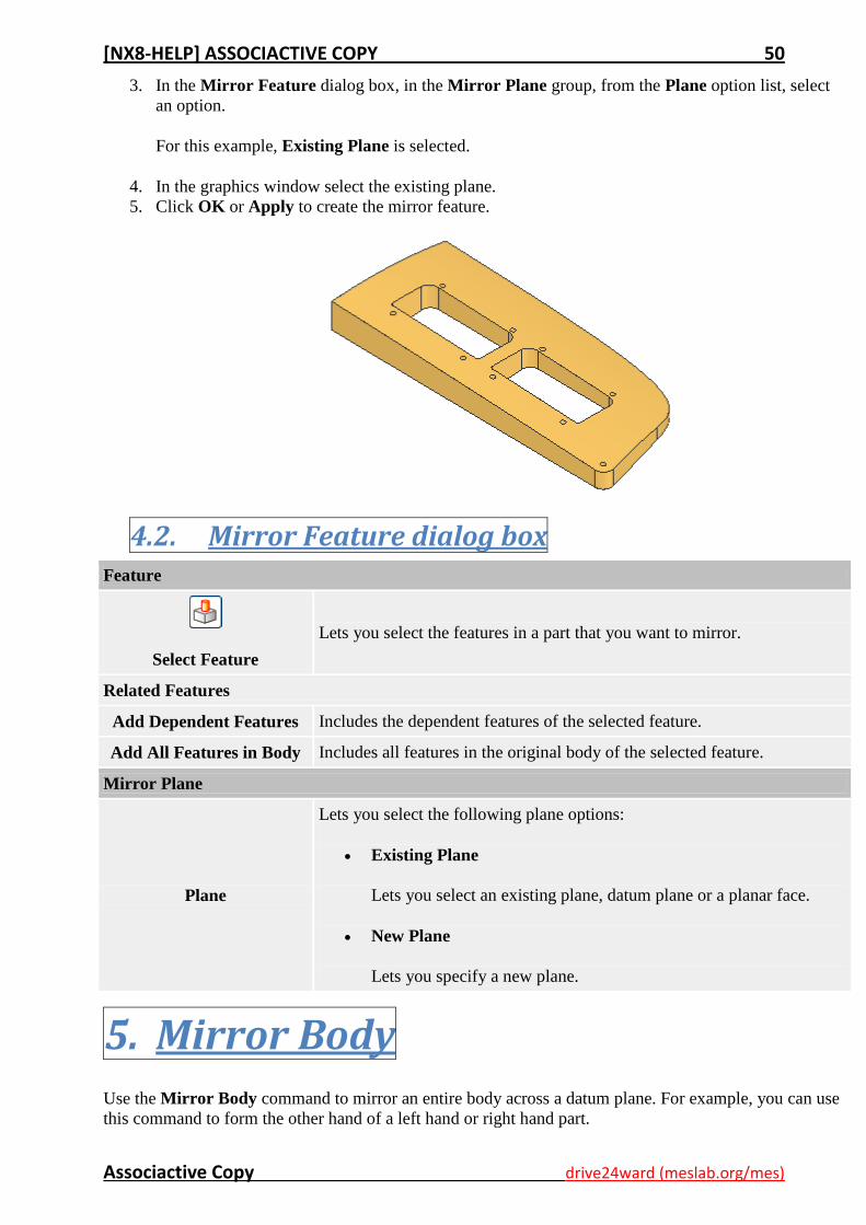
3. In the Mirror Feature dialog box, in the Mirror Plane group, from the Plane option list, select
an option.
For this example, Existing Plane is selected.
4. In the graphics window select the existing plane.
5. Click OK or Apply to create the mirror feature.
4.2. Mirror Feature dialog box Feature
Select Feature
Lets you select the features in a part that you want to mirror.
Related Features
Add Dependent Features Includes the dependent features of the selected feature.
Add All Features in Body Includes all features in the original body of the selected feature.
Mirror Plane
Plane
Lets you select the following plane options:
Existing Plane
Lets you select an existing plane, datum plane or a planar face.
New Plane
Lets you specify a new plane.
5. Mirror Body
Use the Mirror Body command to mirror an entire body across a datum plane. For example, you can use
this command to form the other hand of a left hand or right hand part.
[NX8-HELP] ASSOCIACTIVE COPY 51
Associactive Copy drive24ward (meslab.org/mes)
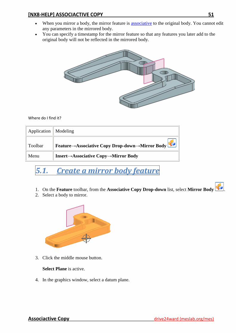
When you mirror a body, the mirror feature is associative to the original body. You cannot edit
any parameters in the mirrored body.
You can specify a timestamp for the mirror feature so that any features you later add to the
original body will not be reflected in the mirrored body.
Where do I find it?
Application Modeling
Toolbar Feature→Associative Copy Drop-down→Mirror Body
Menu Insert→Associative Copy→Mirror Body
5.1. Create a mirror body feature
1. On the Feature toolbar, from the Associative Copy Drop-down list, select Mirror Body .
2. Select a body to mirror.
3. Click the middle mouse button.
Select Plane is active.
4. In the graphics window, select a datum plane.
[NX8-HELP] ASSOCIACTIVE COPY 52
Associactive Copy drive24ward (meslab.org/mes)
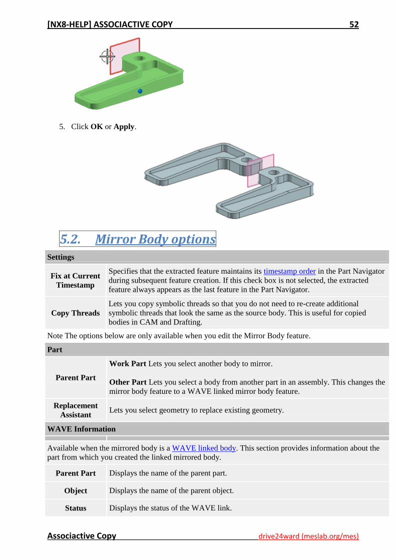
5. Click OK or Apply.
5.2. Mirror Body options Settings
Fix at Current
Timestamp
Specifies that the extracted feature maintains its timestamp order in the Part Navigator
during subsequent feature creation. If this check box is not selected, the extracted
feature always appears as the last feature in the Part Navigator.
Copy Threads
Lets you copy symbolic threads so that you do not need to re-create additional
symbolic threads that look the same as the source body. This is useful for copied
bodies in CAM and Drafting.
Note The options below are only available when you edit the Mirror Body feature.
Part
Parent Part
Work Part Lets you select another body to mirror.
Other Part Lets you select a body from another part in an assembly. This changes the
mirror body feature to a WAVE linked mirror body feature.
Replacement
Assistant Lets you select geometry to replace existing geometry.
WAVE Information
Available when the mirrored body is a WAVE linked body. This section provides information about the
part from which you created the linked mirrored body.
Parent Part Displays the name of the parent part.
Object Displays the name of the parent object.
Status Displays the status of the WAVE link.
[NX8-HELP] ASSOCIACTIVE COPY 53
Associactive Copy drive24ward (meslab.org/mes)
Settings
Associative
Available when Parent Part is set to Other Part.
When the check box is cleared, breaks the link between the Mirror Body feature and
its parent part. The linked feature is not updated when its parent part is changed. You
can define a new parent part at any time.
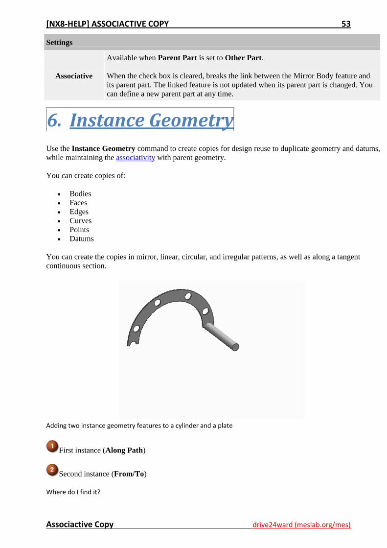
6. Instance Geometry
Use the Instance Geometry command to create copies for design reuse to duplicate geometry and datums,
while maintaining the associativity with parent geometry.
You can create copies of:
Bodies
Faces
Edges
Curves
Points
Datums
You can create the copies in mirror, linear, circular, and irregular patterns, as well as along a tangent
continuous section.
Adding two instance geometry features to a cylinder and a plate
First instance (Along Path)
Second instance (From/To)
Where do I find it?

[NX8-HELP] ASSOCIACTIVE COPY 54
Associactive Copy drive24ward (meslab.org/mes)
Application Modeling
Toolbar Feature→Instance Geometry
Menu Insert→Associative Copy→Instance Geometry
6.1. Create instances to form a chain link
1. On the Feature toolbar, click or choose Insert→Associative Copy→Instance Geometry.
2. In the Instance Geometry dialog box, in the Type group, click Rotate .
Select Object in the Geometry to Instance group is active.
3. Select the geometry to create instances.
For this example, the solid is selected
4. In the Rotation Axis group, click Specify Vector, and select an object to define the rotation axis.
For this example, the line is selected to define the rotation axis.
5. In the Rotation Axis group, click Specify point, and select an object to define the rotation point.
For this example, the mid point of the line is selected to define the rotation point.
[NX8-HELP] ASSOCIACTIVE COPY 55
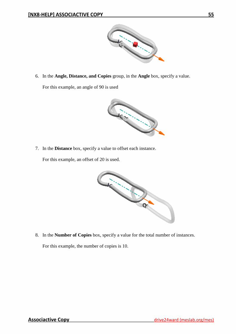
Associactive Copy drive24ward (meslab.org/mes)
6. In the Angle, Distance, and Copies group, in the Angle box, specify a value.
For this example, an angle of 90 is used
7. In the Distance box, specify a value to offset each instance.
For this example, an offset of 20 is used.
8. In the Number of Copies box, specify a value for the total number of instances.
For this example, the number of copies is 10.
[NX8-HELP] ASSOCIACTIVE COPY 56
Associactive Copy drive24ward (meslab.org/mes)
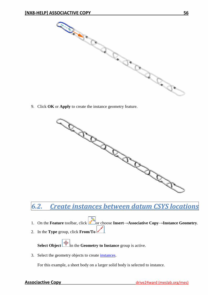
9. Click OK or Apply to create the instance geometry feature.
6.2. Create instances between datum CSYS locations
1. On the Feature toolbar, click or choose Insert→Associative Copy→Instance Geometry.
2. In the Type group, click From/To .
Select Object in the Geometry to Instance group is active.
3. Select the geometry objects to create instances.
For this example, a sheet body on a larger solid body is selected to instance.
[NX8-HELP] ASSOCIACTIVE COPY 57
Associactive Copy drive24ward (meslab.org/mes)
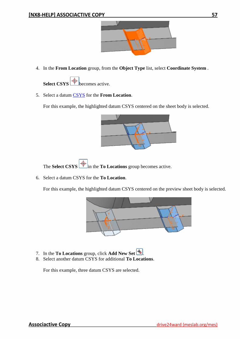
4. In the From Location group, from the Object Type list, select Coordinate System .
Select CSYS becomes active.
5. Select a datum CSYS for the From Location.
For this example, the highlighted datum CSYS centered on the sheet body is selected.
The Select CSYS in the To Locations group becomes active.
6. Select a datum CSYS for the To Location.
For this example, the highlighted datum CSYS centered on the preview sheet body is selected.
7. In the To Locations group, click Add New Set .
8. Select another datum CSYS for additional To Locations.
For this example, three datum CSYS are selected.
[NX8-HELP] ASSOCIACTIVE COPY 58
Associactive Copy drive24ward (meslab.org/mes)
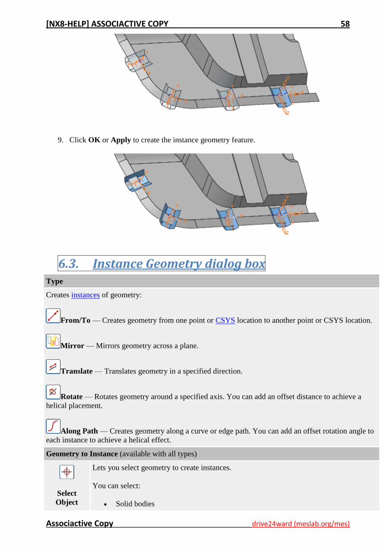
9. Click OK or Apply to create the instance geometry feature.
6.3. Instance Geometry dialog box Type
Creates instances of geometry:
From/To — Creates geometry from one point or CSYS location to another point or CSYS location.
Mirror — Mirrors geometry across a plane.
Translate — Translates geometry in a specified direction.
Rotate — Rotates geometry around a specified axis. You can add an offset distance to achieve a
helical placement.
Along Path — Creates geometry along a curve or edge path. You can add an offset rotation angle to
each instance to achieve a helical effect.
Geometry to Instance (available with all types)
Select
Object
Lets you select geometry to create instances.
You can select:
Solid bodies
[NX8-HELP] ASSOCIACTIVE COPY 59
Associactive Copy drive24ward (meslab.org/mes)
Sheet bodies
Faces
Edges
Curves
Points
Datums
Settings (available with all types)
Associative
Creates a fully associative instance geometry feature.
If you clear this check box, you get separate unparameterized copies of the original
geometry.
Note This option has no effect when creating an instance with either a CSYS or a datum
CSYS. The result is always a datum CSYS.
Hide
Original
Hides the geometry that was selected to create instances.
Note Use the Show and Hide commands on the Edit menu to display objects that are
hidden.
Copy
Threads
Lets you copy symbolic threads so that you do not need to re-create additional symbolic
threads that look the same as the source body. This is useful for copied bodies in CAM and
Drafting.
From/To options
From Location / To Location
Object Type
Lets you choose one of the following methods to specify a location:
Point
Coordinate System
Specify Point
Appears when the Object Type is Point.
Lets you define an origin and destination points for the instance geometry.
You can drag the point handle to a new point position, as long as it satisfies the current
snap point settings.
Select CSYS
Appears when the Object Type is Coordinate System.
Lets you select a coordinate system to define an origin point for the instance geometry.
Add New Set
Adds sets of destination points or coordinate systems to the To Locations list, where
copies of the selected objects to create instances will be located.
List Displays point and coordinate system locations.
To Location 1
[NX8-HELP] ASSOCIACTIVE COPY 60
Associactive Copy drive24ward (meslab.org/mes)
To Location 2
To Location 3
Copies
Number of
Copies Sets the number of copies of the selected geometry to add to the instance.
Mirror options
Settings
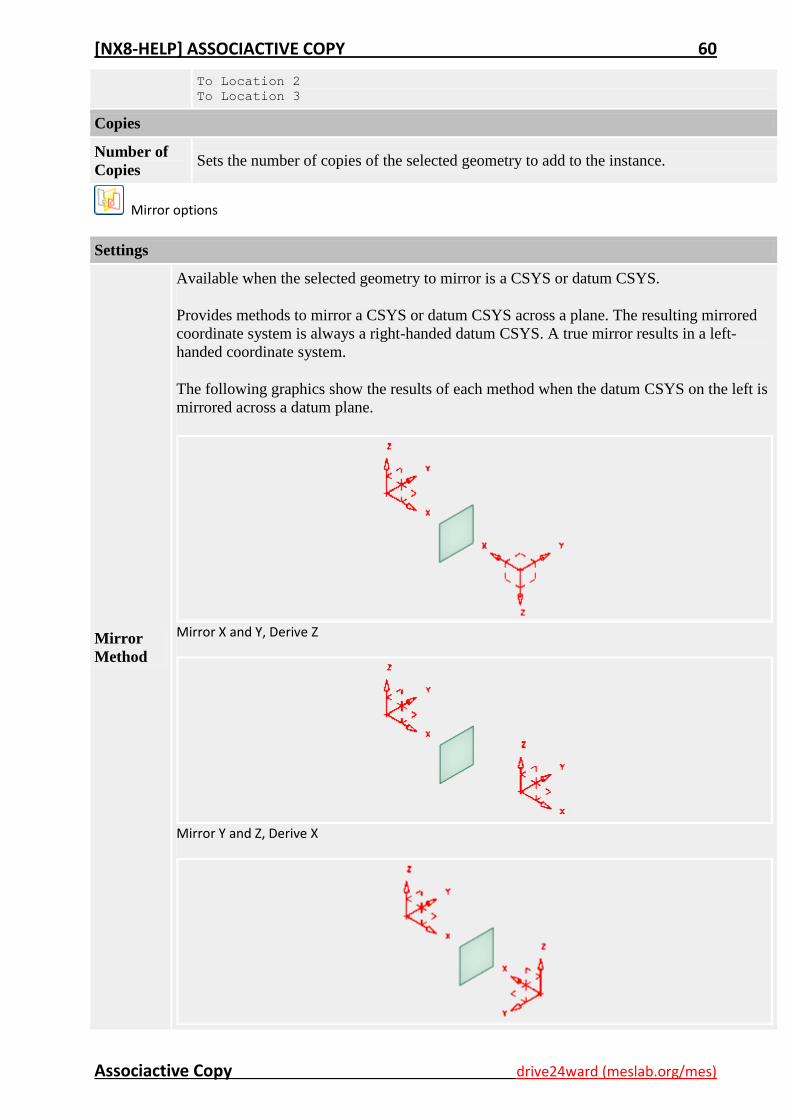
Mirror
Method
Available when the selected geometry to mirror is a CSYS or datum CSYS.
Provides methods to mirror a CSYS or datum CSYS across a plane. The resulting mirrored
coordinate system is always a right-handed datum CSYS. A true mirror results in a left-
handed coordinate system.
The following graphics show the results of each method when the datum CSYS on the left is
mirrored across a datum plane.
Mirror X and Y, Derive Z
Mirror Y and Z, Derive X
[NX8-HELP] ASSOCIACTIVE COPY 61
Associactive Copy drive24ward (meslab.org/mes)
Mirror Z and X, Derive Y
Translate options
Direction
Specify
Vector
Updates the instance geometry if the geometry selected for direction is changed. The
instance geometry and the direction are associative.
Distance and Copies
Distance
Lets you specify a value for the distance separating the instance geometry and the
selected objects.
If you type a value greater than one in the Number of Copies box, the distance value
also specifies the spacing between each successive copy.
Number of
Copies Sets the number of copies of the selected geometry to add to the instance geometry.
Rotate options
Rotation Axis
Specify
Vector
Updates the instance geometry if the geometry selected for direction is changed. The
instance geometry and the direction are associative.
Specify Point
Lets you define an origin point for the rotation of the instance geometry.
You can drag the point handle to a new point position.
Angle, Distance, and Copies
Angle Sets the angle of rotation between each instance geometry.
Distance Adds an offset distance to each rotated copy of the instance geometry to achieve a
helical effect.
Number of
Copies Sets the number of copies of the selected geometry to add to the instance geometry.
Along Path options
Geometry to Instance
Select
Object
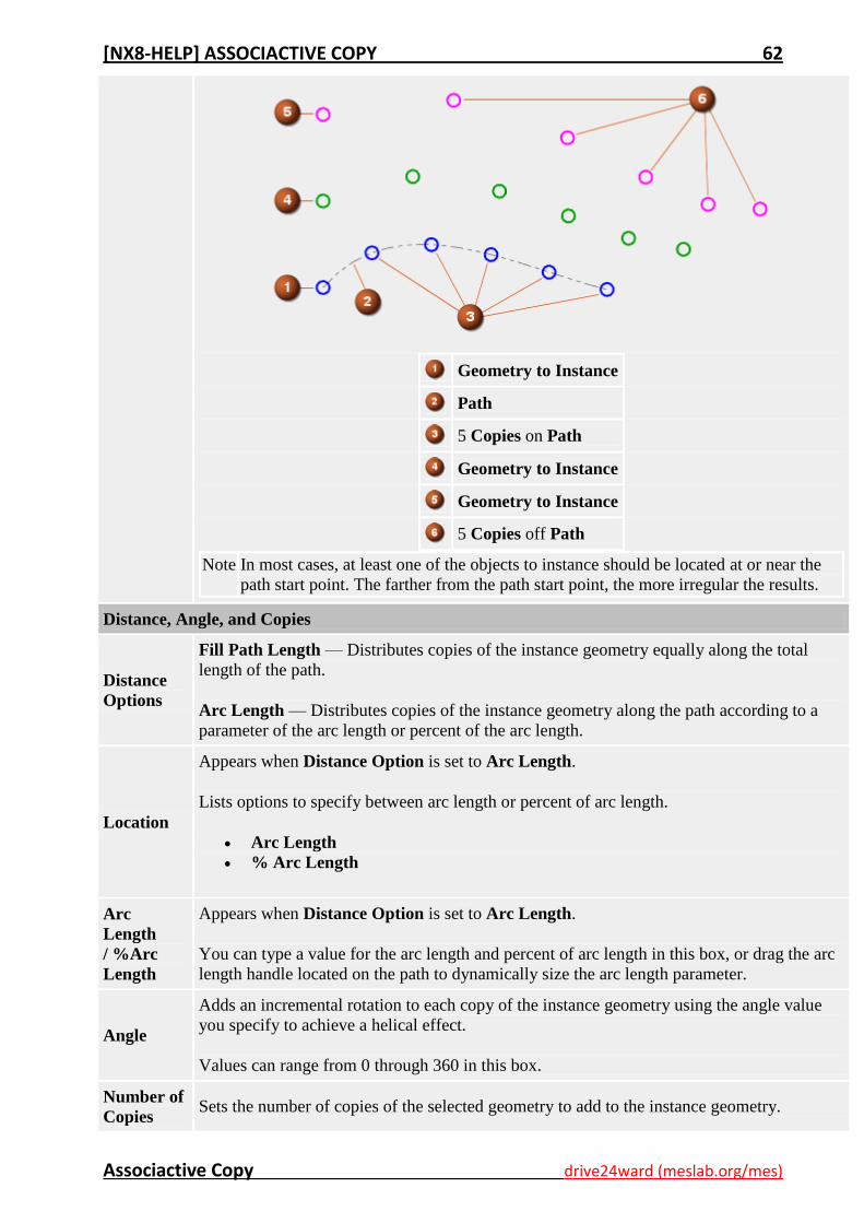
Copies each object you select to a location that is referenced from the path start point.
If an object is located at the path start point, its instances are copied on the path and along it.
If an object is located away from the path start point, its instances are copied along and in
reference to the path, but not on it.
[NX8-HELP] ASSOCIACTIVE COPY 62
Associactive Copy drive24ward (meslab.org/mes)
Geometry to Instance
Path
5 Copies on Path
Geometry to Instance
Geometry to Instance
5 Copies off Path
Note In most cases, at least one of the objects to instance should be located at or near the
path start point. The farther from the path start point, the more irregular the results.
Distance, Angle, and Copies
Distance
Options
Fill Path Length — Distributes copies of the instance geometry equally along the total
length of the path.
Arc Length — Distributes copies of the instance geometry along the path according to a
parameter of the arc length or percent of the arc length.
Location
Appears when Distance Option is set to Arc Length.
Lists options to specify between arc length or percent of arc length.
Arc Length
% Arc Length
Arc
Length
/ %Arc
Length
Appears when Distance Option is set to Arc Length.
You can type a value for the arc length and percent of arc length in this box, or drag the arc
length handle located on the path to dynamically size the arc length parameter.
Angle
Adds an incremental rotation to each copy of the instance geometry using the angle value
you specify to achieve a helical effect.
Values can range from 0 through 360 in this box.
Number of
Copies Sets the number of copies of the selected geometry to add to the instance geometry.
[NX8-HELP] ASSOCIACTIVE COPY 63
Associactive Copy drive24ward (meslab.org/mes)
7. Promote Body Use the Promote Body command to promote a body from a loaded assembly component to the level of
the assembly.
You do not need write access to the part containing the original, or the base body, in order to promote it.
This can be especially important when working in a concurrent engineering environment.
After you promote a body:
You can perform operations on it, such as adding features, performing Boolean operations
between it and other bodies, and so on. The effects of these operations are only visible at the level
of the assembly work part in which the promotion is created, and in any other assembly that
references that part.
You cannot access the features that make up the base body at the assembly level. For example,
you cannot suppress a feature of the base body, or change its parameters and have those changes
occur only at assembly level. You must make such changes to the base body. They will be visible
in the promoted body, since it is associative to the base body.
Any subsequent changes to the base body are reflected in the promoted body as the promoted
body is associative to the base body. However, changes made to a promoted body do not affect the
base body.
Caution You must be careful when working "in context" (that is, with the work part different than the
displayed part) with promoted bodies. If the assembly is the displayed part and the component is
the work part, the promoted body is still displayed and this blocks the display of the base body.
You should change the displayed part to the component to work on the base body.
Warning You should not promote a body that depends on another body in the same part. A dependent
body is created by features that generate a new body, such as a mirror body feature, an extract
face feature or a midsurface feature. If you promote a dependent body and then suppress or
delete the parent body or feature, you may get internal errors.
Where do I find it?
Application Modeling
Prerequisite The work part must be an assembly.
Toolbar Feature→Associative Copy Drop-down→Promote Body
Menu Insert→Associative Copy→Promote Body
Customer defaults for Promote Body are at:
Menu File→Utilities→Customer Defaults
Location in dialog box Customer Defaults→Assemblies→Interpart Modeling→Allow Promote Body
7.1. Promote a body
1. Open an assembly. The assembly must be the work part, and the component containing the body
you want to promote must be loaded.
2. Choose Insert→Associative Copy→Promote Body.

[NX8-HELP] ASSOCIACTIVE COPY 64
Associactive Copy drive24ward (meslab.org/mes)
3. In the Promote Body dialog box click Select Body and select the required body from the
graphics window.
4. Click OK or Apply. The selected body is promoted to the assembly level.
7.2. Substitute a promoted part
You can use the Assembly Navigator to substitute the base component of a promoted part.
1. In an assembly part, open the Assembly Navigator.
2. In the Assembly Navigator, highlight the component you want to substitute, right-click and
choose Close→Part.
3. Highlight the same part, which is now closed, right-click and choose Open→Component As.
4. In the File dialog box, select the new part to substitute in.
If the new part is a version of the original part, and the base body of the promotion exists in the
new part, the promotion is updated to the new base body.
If the new part and the original parts are not versions of each other, and if you select Allow
Substitution in the Load Options dialog box, the promotion feature is presented in the Update
Failure dialog box, and you can then make the required changes.
7.3. Edit a Promote Body feature Note Editing the Promote Body feature could result in a loss of data. Unloaded parts may be affected.
Exploded views will be affected. The base body will become visible. There is no operation to
reparent promotions after saving.
1. Choose Edit→Feature→Edit Parameters.
The Edit Parameters dialog box opens.
2. Choose the Promote Body feature from the list and click OK.
The edit version of the Promote Body dialog box opens.
3. (Optional) To break the link between the Promote Body feature and its parent assembly, clear the
Associative option.
Warning This action breaks the link between the promoted body and the assembly parent.
4. (Optional) To change the Promote Body feature to a WAVE Linked Body, select the Convert to
Linked Body option.
Note This action turns the Promote Body feature into a WAVE Linked Body. If you later edit it,
the edit version of the WAVE Geometry Linker opens. See the Assemblies help for details.
5. Click OK or Apply to make the changes effective.
[NX8-HELP] ASSOCIACTIVE COPY 65
Associactive Copy drive24ward (meslab.org/mes)
7.4. Promote Body options Body
Select Body
Lets you select the body to promote
Promote Body terms
The following terms are used for Promote Body:
Term Description
Promoted Body A body that has been promoted.
Base Body The original body.
Base Component A component from which at least one body has been promoted.
7.5. Promote Body restrictions
Promoted bodies have the following restrictions:
All Modeling operations that cause the model to lose its parameterization or feature history, are
not available for promoted bodies.
You cannot reorder a promoted body into the component's feature list, or vice versa. You can
manipulate a promoted body only when the part that it was defined in is the work part.
You cannot split a promoted body into multiple bodies.
If you move a body to another part of the assembly tree after it is promoted, the promotion is
deleted.
When you translate parts, promoted bodies are not translated.
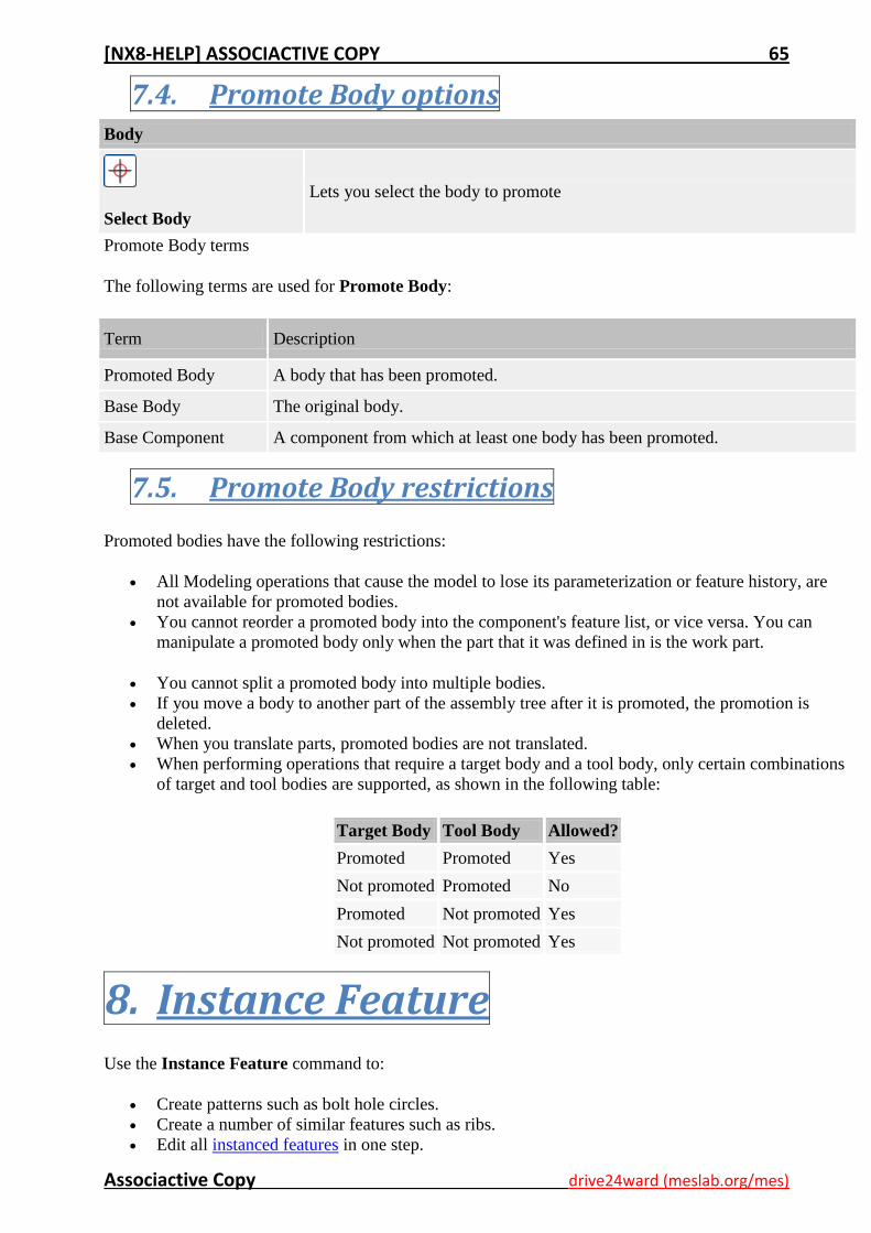
When performing operations that require a target body and a tool body, only certain combinations
of target and tool bodies are supported, as shown in the following table:
Target Body Tool Body Allowed?
Promoted Promoted Yes
Not promoted Promoted No
Promoted Not promoted Yes
Not promoted Not promoted Yes
8. Instance Feature
Use the Instance Feature command to:
Create patterns such as bolt hole circles.
Create a number of similar features such as ribs.
Edit all instanced features in one step.
[NX8-HELP] ASSOCIACTIVE COPY 66
Associactive Copy drive24ward (meslab.org/mes)
You can define three Instance Feature types:
Rectangular Array
Circular Array
Pattern Face
You can add edge blends, chamfers, and threads to an Instance feature.
If you create:
An edge blend you can select Blend All Instances.
A chamfer you can select Chamfer All Instances.
A thread you can select Include Instances
When you select these options, always add the edge blend, chamfer or thread to the master feature,
and not to one of the instanced features. This way, if the array parameters are changed, the edge
blend, chamfer or thread will always remain visible in the instance set.
You cannot instance the following objects:
Shells
Chamfers
Blends
Offset sheets
Datums
Trimmed sheet bodies
Instance sets
Draft features
Surfaces
Trimmed features
Associative points
Where do I find it?
Application Modeling
Toolbar Feature→Instance Feature
Menu Insert→Associative Copy→Instance Feature
8.1. Rectangular Array
Use the Rectangular Array command to create a linear pattern of one or more selected features.
Rectangular arrays can be:
One-dimensional in XC or YC, with one row of features.
Two-dimensional in XC and YC, with several rows of features.
[NX8-HELP] ASSOCIACTIVE COPY 67
Associactive Copy drive24ward (meslab.org/mes)
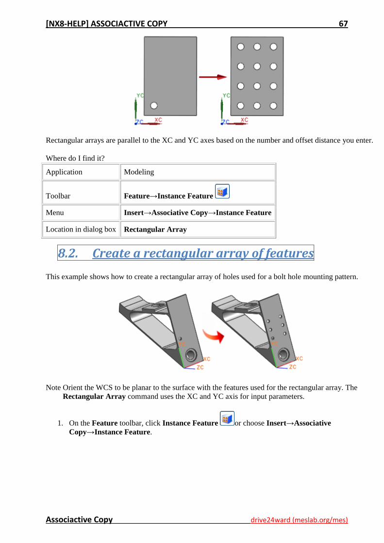
Rectangular arrays are parallel to the XC and YC axes based on the number and offset distance you enter.
Where do I find it?
Application Modeling
Toolbar Feature→Instance Feature
Menu Insert→Associative Copy→Instance Feature
Location in dialog box Rectangular Array
8.2. Create a rectangular array of features
This example shows how to create a rectangular array of holes used for a bolt hole mounting pattern.
Note Orient the WCS to be planar to the surface with the features used for the rectangular array. The
Rectangular Array command uses the XC and YC axis for input parameters.
1. On the Feature toolbar, click Instance Feature or choose Insert→Associative
Copy→Instance Feature.
[NX8-HELP] ASSOCIACTIVE COPY 68
Associactive Copy drive24ward (meslab.org/mes)
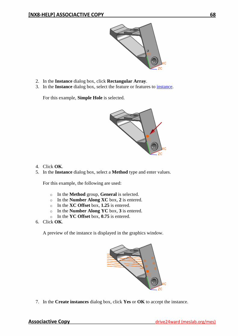
2. In the Instance dialog box, click Rectangular Array.
3. In the Instance dialog box, select the feature or features to instance.
For this example, Simple Hole is selected.
4. Click OK.
5. In the Instance dialog box, select a Method type and enter values.
For this example, the following are used:
o In the Method group, General is selected.
o In the Number Along XC box, 2 is entered.
o In the XC Offset box, 1.25 is entered.
o In the Number Along YC box, 3 is entered.
o In the YC Offset box, 0.75 is entered.
6. Click OK.
A preview of the instance is displayed in the graphics window.
7. In the Create instances dialog box, click Yes or OK to accept the instance.

[NX8-HELP] ASSOCIACTIVE COPY 69
Associactive Copy drive24ward (meslab.org/mes)
8. Click Cancel to exit the Instance dialog box.
8.3. Circular Array
Use the Circular Array command to create a circular pattern of one or more selected features.
Circular arrays require the following:
An axis of revolution.
A reference point to revolve about.
Where do I find it?
Application Modeling
Toolbar Feature→Instance Feature
Menu Insert→Associative Copy→Instance Feature
Location in dialog box Circular Array
8.4. Create a circular array of features
This example shows how to create a circular array of features used to complete a symmetrical part.
[NX8-HELP] ASSOCIACTIVE COPY 70
Associactive Copy drive24ward (meslab.org/mes)
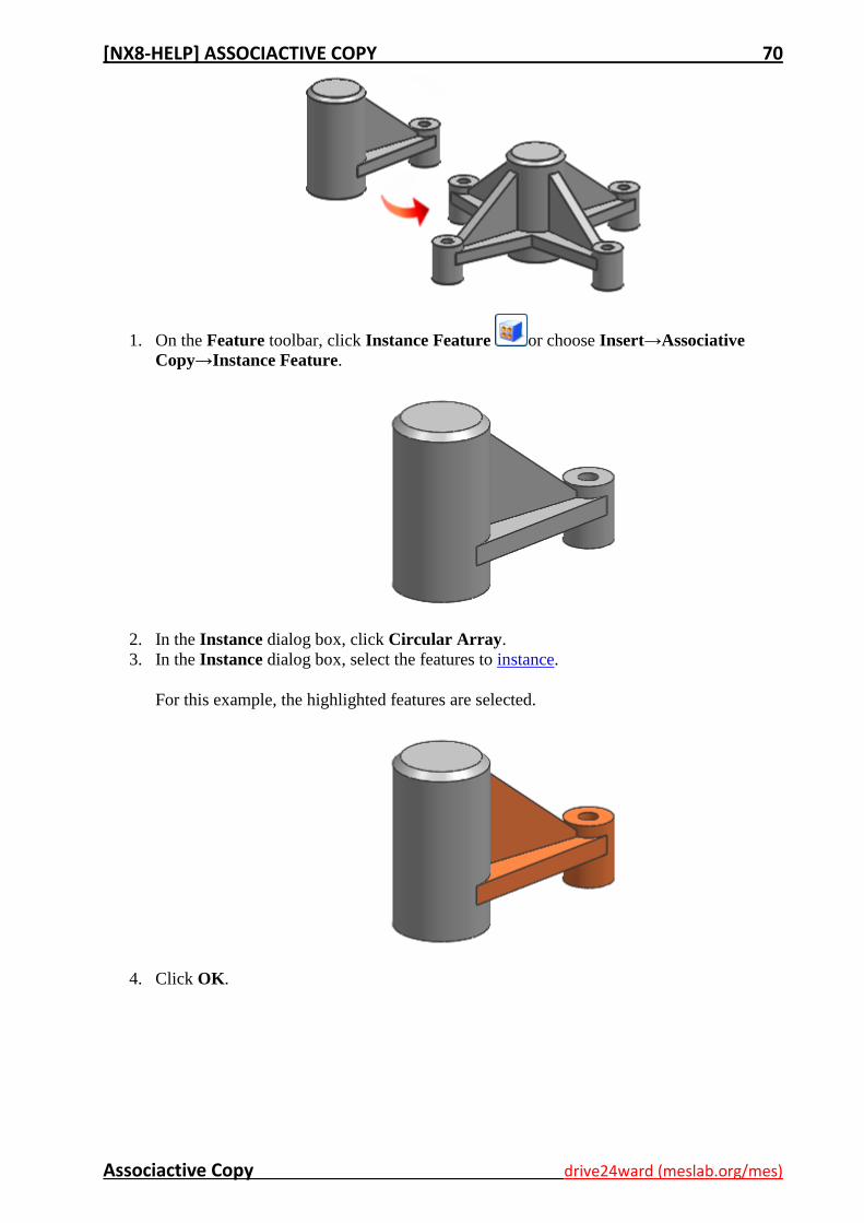
1. On the Feature toolbar, click Instance Feature or choose Insert→Associative
Copy→Instance Feature.
2. In the Instance dialog box, click Circular Array.
3. In the Instance dialog box, select the features to instance.
For this example, the highlighted features are selected.
4. Click OK.
[NX8-HELP] ASSOCIACTIVE COPY 71
Associactive Copy drive24ward (meslab.org/mes)
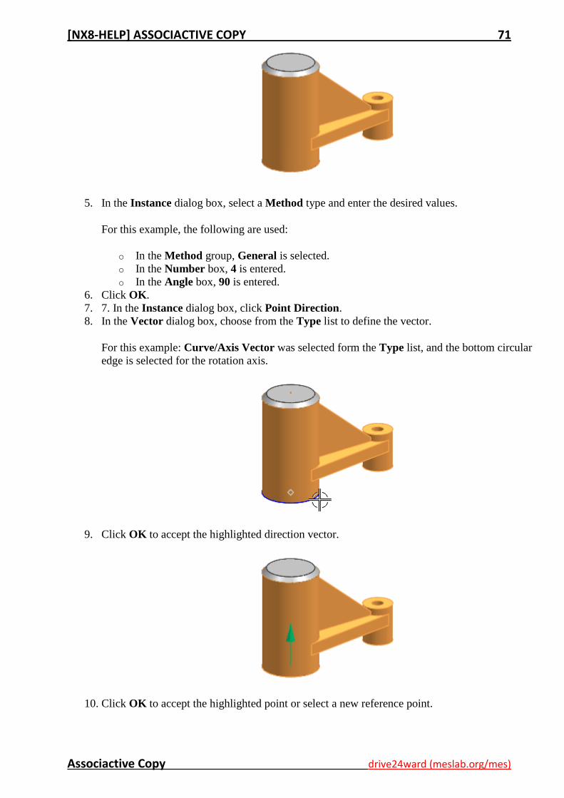
5. In the Instance dialog box, select a Method type and enter the desired values.
For this example, the following are used:
o In the Method group, General is selected.
o In the Number box, 4 is entered.
o In the Angle box, 90 is entered.
6. Click OK.
7. 7. In the Instance dialog box, click Point Direction.
8. In the Vector dialog box, choose from the Type list to define the vector.
For this example: Curve/Axis Vector was selected form the Type list, and the bottom circular
edge is selected for the rotation axis.
9. Click OK to accept the highlighted direction vector.
10. Click OK to accept the highlighted point or select a new reference point.
[NX8-HELP] ASSOCIACTIVE COPY 72
Associactive Copy drive24ward (meslab.org/mes)
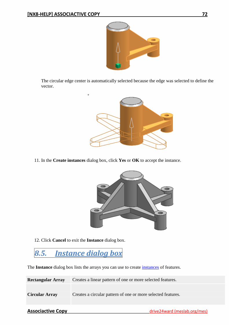
The circular edge center is automatically selected because the edge was selected to define the
vector.
11. In the Create instances dialog box, click Yes or OK to accept the instance.
12. Click Cancel to exit the Instance dialog box.
8.5. Instance dialog box
The Instance dialog box lists the arrays you can use to create instances of features.
Rectangular Array Creates a linear pattern of one or more selected features.
Circular Array Creates a circular pattern of one or more selected features.
[NX8-HELP] ASSOCIACTIVE COPY 73
Associactive Copy drive24ward (meslab.org/mes)
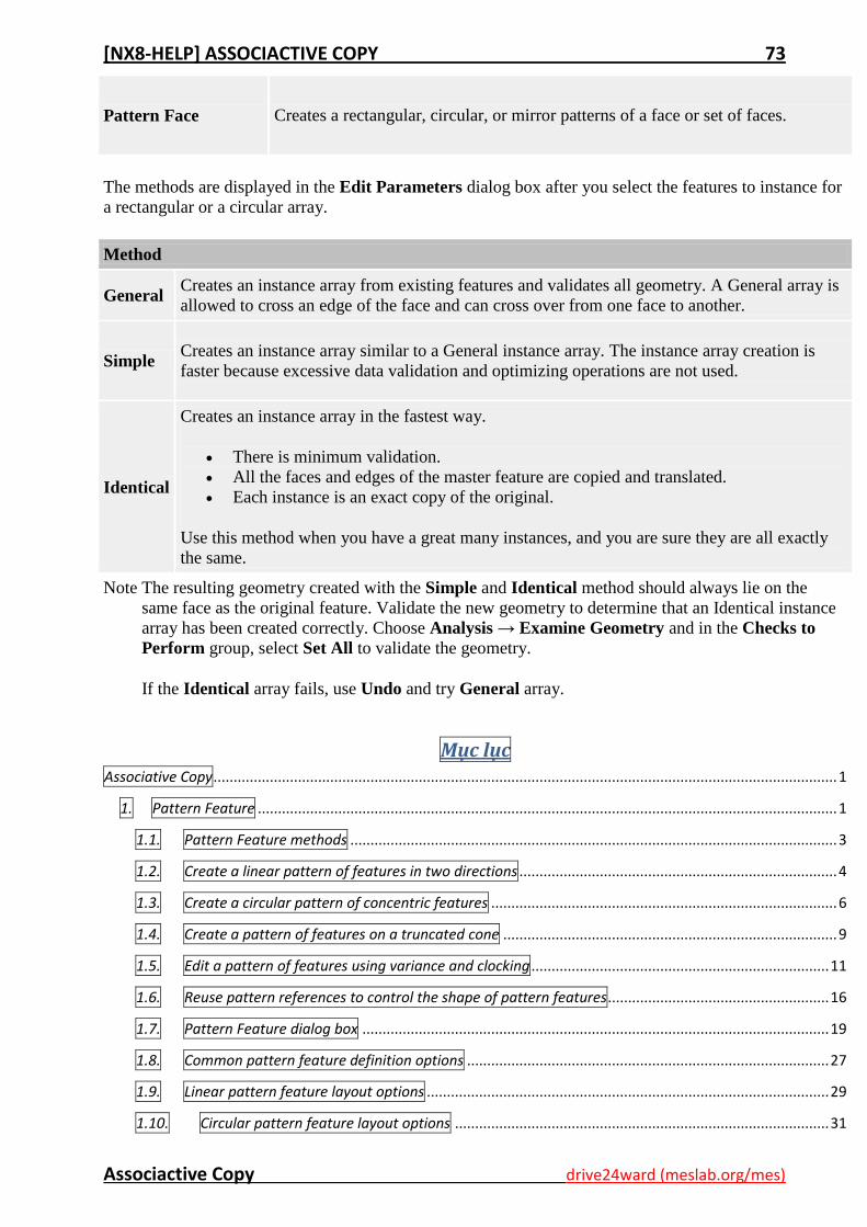
Pattern Face Creates a rectangular, circular, or mirror patterns of a face or set of faces.
The methods are displayed in the Edit Parameters dialog box after you select the features to instance for
a rectangular or a circular array.
Method
General Creates an instance array from existing features and validates all geometry. A General array is
allowed to cross an edge of the face and can cross over from one face to another.
Simple Creates an instance array similar to a General instance array. The instance array creation is
faster because excessive data validation and optimizing operations are not used.
Identical
Creates an instance array in the fastest way.
There is minimum validation.
All the faces and edges of the master feature are copied and translated.
Each instance is an exact copy of the original.
Use this method when you have a great many instances, and you are sure they are all exactly
the same.
Note The resulting geometry created with the Simple and Identical method should always lie on the
same face as the original feature. Validate the new geometry to determine that an Identical instance
array has been created correctly. Choose Analysis → Examine Geometry and in the Checks to
Perform group, select Set All to validate the geometry.
If the Identical array fails, use Undo and try General array.
Mục lục Associative Copy ........................................................................................................................................................... 1
1. Pattern Feature ................................................................................................................................................ 1
1.1. Pattern Feature methods ......................................................................................................................... 3
1.2. Create a linear pattern of features in two directions ............................................................................... 4
1.3. Create a circular pattern of concentric features ...................................................................................... 6
1.4. Create a pattern of features on a truncated cone ................................................................................... 9
1.5. Edit a pattern of features using variance and clocking .......................................................................... 11
1.6. Reuse pattern references to control the shape of pattern features ....................................................... 16
1.7. Pattern Feature dialog box .................................................................................................................... 19
1.8. Common pattern feature definition options .......................................................................................... 27
1.9. Linear pattern feature layout options .................................................................................................... 29
1.10. Circular pattern feature layout options ............................................................................................. 31
[NX8-HELP] ASSOCIACTIVE COPY 74
Associactive Copy drive24ward (meslab.org/mes)
1.11. Polygon pattern feature layout options ............................................................................................. 33
1.12. Spiral pattern feature layout options ................................................................................................. 34
1.13. Along pattern feature layout options................................................................................................. 35
1.14. Path methods for the Along layout .................................................................................................... 36
1.15. General pattern feature layout options ............................................................................................. 37
1.16. Reference pattern feature layout options .......................................................................................... 37
1.17. Spacing options by layout .................................................................................................................. 39
2. Extract Body ................................................................................................................................................... 39
2.1. Extract a region of face bodies ............................................................................................................... 40
2.2. Extract Body dialog box .......................................................................................................................... 42
2.3. Extract Body edit options ....................................................................................................................... 44
3. Composite Curve ............................................................................................................................................ 45
3.1. Create a composite curve ....................................................................................................................... 45
3.2. Composite Curve dialog box ................................................................................................................... 46
4. Mirror Feature ................................................................................................................................................ 48
4.1. Create a mirror feature .......................................................................................................................... 49
4.2. Mirror Feature dialog box ...................................................................................................................... 50
5. Mirror Body .................................................................................................................................................... 50
5.1. Create a mirror body feature ................................................................................................................. 51
5.2. Mirror Body options ............................................................................................................................... 52
6. Instance Geometry ......................................................................................................................................... 53
6.1. Create instances to form a chain link ..................................................................................................... 54
6.2. Create instances between datum CSYS locations ................................................................................... 56
6.3. Instance Geometry dialog box ............................................................................................................... 58
7. Promote Body ................................................................................................................................................. 63
7.1. Promote a body ...................................................................................................................................... 63
7.2. Substitute a promoted part .................................................................................................................... 64
7.3. Edit a Promote Body feature .................................................................................................................. 64
7.4. Promote Body options ............................................................................................................................ 65
7.5. Promote Body restrictions ...................................................................................................................... 65
8. Instance Feature ............................................................................................................................................. 65
8.1. Rectangular Array .................................................................................................................................. 66
8.2. Create a rectangular array of features .................................................................................................. 67
8.3. Circular Array ......................................................................................................................................... 69
[NX8-HELP] ASSOCIACTIVE COPY 75
Associactive Copy drive24ward (meslab.org/mes)
8.4. Create a circular array of features ......................................................................................................... 69
8.5. Instance dialog box ................................................................................................................................ 72