ancore pentru sarcini mici / metalice · 2010-10-07 · wlefd dibluri cu clapetă cu arc efd-hm cu...
TRANSCRIPT

wdHUS Sistem cu şurub universal(se va monta cu maşină de înşurubat cu impuls tangenţial TKI 2500)
Date tehnice Şurub universal HUS-/-S/-H/-AExtras din Manualul tehncii de ancorare Hilti
Material de ancorareBeton C20/25 Cărămidă
din var cu nisipCărămidăcu goluri
Beton porosG2/G4
Forţă tracţiune rec.(zonă întinsă / comp.) [kN] 1,0 1,0 0,1 0,2Forţă forfecare rec.V la dist.de margini³ 60mm [KN] 1,6 1,1 0,4 0,3Forţă forfecare rec.V la dist.de margini ³ 30mm [KN] 0,5 0,4 0,2 0,1Diametru gaură do [mm] 6 6 6 –Adâncime minimă de găurire h1 [mm] 40 50 70 –Adâncime minimă de montaj hnom [mm] 30 40 60 60
HUS Şurub universal, x cap 10,2 mm, T40, x gaură 6 mm
5 0 0 35 HUS 7,5x 35 71260 10015 5 0 45 HUS 7,5x 45 71261 10030 20 0 60 HUS 7,5x 60 71278 10050 40 20 80 HUS 7,5x 80 71279 10070 60 40 100 HUS 7,5x100 71280 10090 80 60 120 HUS 7,5x120 71281 100
110 100 80 140 HUS 7,5x140 71282 100130 120 100 160 HUS 7,5x160 71283 100150 140 120 180 HUS 7,5x180 71284 100170 160 140 200 HUS 7,5x200 309350 100190 180 160 220 HUS 7,5x220 309351 100
HUS-S Şuruburi pentru ferestre x cap 7.7 mm, T 30,
x gaură 6 mm
30 20 0 60 HUS-S 7,5x 60 373472 10050 40 20 80 HUS-S 7,5x 80 373473 10070 60 40 100 HUS-S 7,5x100 230117 10090 80 60 120 HUS-S 7,5x120 230118 100
110 100 80 140 HUS-S 7,5x140 230119 100130 120 100 160 HUS-S 7,5x160 230120 100150 140 120 180 HUS-S 7,5x180 230121 100170 160 140 200 HUS-S 7,5x200 309352 100190 180 160 220 HUS-S 7,5x220 309353 100
Capac de protecţie din material plastic pentru şurub universal HUS (T40)
Culoare Execuţie Cod comandă Nr. articol Buc./ambalaj
alb suprapus HKO-T40 W 246777 200maro deschis suprapus HKO-T40 HB 246778 200maro închis suprapus HKO-T40 DB 246779 200alb plat HKF-T40 W 246780 200maro deschis plat HKF-T40 HB 246781 200maro închis plat HKF-T40 DB 246782 200
Alte date tehnice puteţi găsi în Manualul tehnicii de ancorare Hilti,sau pe Internet la adresa www.hilti.ro.
Înălţimi max. de fixare (mm)beton (recomand. Hilti)
Cărămidă plinăCărămidă var cu nisip
Lungimeşurub (mm)
Cod comandă Buc./ambalaj
Nr. articolCărămidă cu goluribeton poros
Înălţimi max. de fixare (mm)beton (recomand. Hilti)
Cărămidă plinăCărămidă var cu nisip
Lungimeşurub (mm)
Cod comandă Buc./ambalaj
Nr. articolCărămidă cu goluribeton poros
157
Tehn
ica
anco
rări
i
Ancore pentru sarcini mici / Metalice

HUS-A Ancoră şurub cu filet de racord, metric,gaură x 6mm
M 8 18 45 HUS-A 7,5x45 – M 8/18 309346 100M 8 18 65 HUS-A 7,5x65 – M 8/18 309347 100M10 21 45 HUS-A 7,5x45 – M 10/21 309348 100M10 21 65 HUS-A 7,5x65 – M 10/21 309349 100
HUS-H Ancoră şurub combinată cu cap hexagonalSW 13 şi T40, gaură x 6 mm
5 0 0 35 HUS-H 7,5x 35 309340 10015 5 0 45 HUS-H 7,5x 45 309341 10030 20 0 60 HUS-H 7,5x 60 309342 10050 40 20 80 HUS-H 7,5x 80 309343 10070 60 40 100 HUS-H 7,5x100 309344 10090 80 60 120 HUS-H 7,5x120 309345 100
Capac de protecţie din material plastic pentru şurub pentru ferestre HUS-S (T30)
alb plat HKF-T30 W 246783 200maro deschis plat HKF-T30 DB 246784 200
Culoare Execuţie Cod comandă Nr. articol Buc./ambalaj
Înălţimi max. de fixare (mm)beton (recomand. Hilti)
Cărămidă plinăCărămidă var cu nisip
Lungimeşurub (mm)
Cod comandă Buc./ambalaj
Nr. articolCărămidă cu goluribeton poros
Filetmetric
Lungimefilet (mm)
Codcomandă
Nr. articol Buc./ambalaj
Lungimeşurub (mm)
158
Ancore pentru sarcini mici / Metalice

159
Ancore pentru sarcini mici / Metalice
wfHT Dibluri metalice pentru rame
HT 8 L
Execuţie: cu şurub cu cap semirotund plat Ø 9 mm. Utilizare: profile din material plasticşi aluminiu cu lăţimi ale canalului de îmbinare sub 11 mm. Cap şurub: Pozidriv mărime 2Lungimediblu l (mm)
x ext. mm =x nominal burghiu D (mm)
Cap şurubx (mm)
Codcomandă
Nr. articol Buc./ambalaj
Adâncime min.de montajh (mm)nom
8 30 9 HT 8 / 72 L 369257 1008 30 9 HT 8 / 92 L 369258 1008 30 9 HT 8 / 112 L 369259 1008 30 9 HT 8 / 132 L 369260 100
7292
112132
HT 10
Execuţie: cu şurub cu cap înecat x 13 mm. Utilizare: pentru rame de ferestre şi căptuşeli de uşi. Cap şurub: Pozidriv mărime 3.
10 30 13 HT10/ 72 369263 10010 30 13 HT10/ 92 369264 10010 30 13 HT10/112 369265 10010 30 13 HT10/132 369266 10010 30 13 HT10/152 369267 10010 30 13 HT10/182 248424 100
7292
112132152182202 10 30 13 HT10/202 248425 100
wgHAM Ancore pentru zidărie
HAM Ancoră pentru zidărie cu filet interior
12 60 HAM M 6 305853 10014 75 HAM M 8 305854 5016 85 HAM M10 305855 2520 95 HAM M12 305856 25
HAM Ancoră pentru zidărie, execuţie cu şurub,inclusiv calitate oţel 8.8
12 60 30 HAM M 6x50 305857 10014 75 40 HAM M 8x60 305858 5016 85 50 HAM M10x80 305859 2520 95 60 HAM M12x90 305860 25
NOU
NOU
Lungimediblu l (mm)
x ext. mm =x nominal burghiu D (mm)
Cap şurubx (mm)
Codcomandă
Nr. articol Buc./ambalaj
Adâncime min.de montajh (mm)nom
x gaurăD (mm)
x gaurăD (mm)
Codcomandă
Codcomandă
Nr. articol
Nr. articol
Buc./ambalaj
Buc./ambalaj
Adâncimegaură BT (mm)
Adâncimegaură BT (mm)
Grosime max. a materialuluide fixat S (mm)max
Tehn
ica
anco
rări
i

160
wkHHD-S Dibluri pentru materialecu cavităţi cu şurub premontat
Date tehnice:HHD-S
M4/20 M4/38 M5/38 M5/52 M6/38 M6/52 M 8/54
Nrec Gipscarton d = 9 (12,5) mm kN 0,2 (0,2) 0,2 (–) 0,2 (0,2) 0,15 (–) 0,2 (0,2) (0,2)
Vrec Gipscarton d = 9 (12,5) mm kN 0,5 (0,5) 0,5 (–) 0,5 (0,5) 0,4 (–) 0,5 (0,5) (0,5)
Nrec Placă din fibră dură = 4 mm kN 0,1Vrec Placă din fibră dură = 4 mm kN 0,4do Diametrul găurii mm 8 8 10 10 12 12 12h Grosimea mat. de fixare mm 4 12 8 12 9 12 12Is Lungimea şurubului mm 25 45 45 58 45 58 60tIfix Grosimea piesei fixate
Lungimea diblului mmmm
1520
1538
2338
2352
1938
2252
2254
HHD-S Dibluri pentru materialecu cavităţi cu şurub premontatMaterial: oţel zincat galvanic
8 20 25 M4 4 HHD-S M4/ 4x20 332060 1008 32 38 M4 6 HHD-S M4/ 6x32 332061 1008 38 45 M4 12 HHD-S M4/12x38 332062 1008 45 52 M4 19 HHD-S M4/19x45 332063 50
10 38 45 M5 8 HHD-S M5/ 8x38 332065 100 10 52 58 M5 12 HHD-S M5/12x52 332066 5010 65 71 M5 25 HHD-S M5/25x65 332067 5012 38 45 M6 9 HHD-S M6/ 9x38 332069 10012 52 58 M6 12 HHD-S M6/12x52 332070 5012 65 71 M6 24 HHD-S M6/24x65 332071 5012 80 88 M6 40 HHD-S M6/40x80 332072 5012 54 60 M8 12 HHD-S M8/12x541) 332073 5012 66 70 M8 24 HHD-S M8/24x661) 332074 5012 83 90 M8 40 1)HHD-S M8/40x83 332075 50* grosimea materialului de ancorare la premontare 1) execuţie cu cap hexagonal SW 13
Cleşte de montaj pentru HHD-Spentru montarea rapidă şi controlată a diblurilor Hilti pentru materiale cu cavităţi HHD-S
Descriere Cod comandă Nr. articol Buc./ambalaj
Cleşte de montaj HHD-SZ HHD-SZ 332076 1
wlEFD Dibluricu clapetă cu arc
EFD-HM cu cârlig rotund
15 M 4 95 EFD-HM4 71256 5018 M 6 125 EFD-HM6 308890 25
EFD-RM cu tijă filetată şi inel
15 M 4 90 EFD-RM4 71250 5018 M 6 100 EFD-RM6 308889 25
Material:n
n
n
Zidărie din cărămizi cu goluri Plăci din ghips-cartonPlanşee de camere, cu goluri
Utilizare:nFixarea de şipci, şine, plăci, elemente
decorative
Material: nExecuţie complet din metal, zincat galvanic
Instrucţiuni de montaj:
Sarcini mici / Metalice
x gaurăd (mm)0
Codcomandă
Nr. articol Buc./ambalaj
Lungimeiblu l (mm)d
Lungimeşurub l (mm)s
Grosime materialh + t (mm)*max
x şurubd (mm)
x gaură(mm)
Codcomandă
Nr. articol Buc./ambalaj
Dimensiunefilet mm
Lungime totalăcârlig (tijă) mm
x gaură(mm)
Codcomandă
Nr. articol Buc./ambalaj
Dimensiunefilet mm
Lungime totalăcârlig (tijă) mm
Is Is
tfix tfix

161
Sarcini mici / Metalice
e0MF-SKD Dibluri basculante
x ştiftfiletat (mm)
x nominalburghiu (mm)
Lungime utilă ştiftfiletat după montaj (mm)
Codcomandă
Nr. articol Buc./ambalaj
Lungime(mm)
Înălţime max.fixare tfix[mm]
x nominalburghiu d (mm)0
Adâncime min.montare h (mm)nom
Adâncimegaură h (mm)1
Lungimediblu (mm)
Codcomandă
Nr. articol Buc./ambalaj
M 8 100 22 65 MF-SKD M 8/100 230604 25M 8 200 22 165 MF-SKD M 8/200 230605 25M 8 300 22 265 MF-SKD M 8/300 230606 25M 8 500 22 465 MF-SKD M 8/500 230607 25M10 100 25 65 MF-SKD M10/100 230608 25M10 200 25 165 MF-SKD M10/200 230609 25
DBZ 6/4,5 şi DBZ 6/35Cuie tip panăMaterial: oţel, zincat galvanic 5 μm
4,5 6 40 40 32 DBZ 6/4,5 256312 10035 6 40 70 32 DBZ 6/35 256311 100
eaDBZ Cuie tip pană
esHA 8 Dibluri cu inel / Dibluri cu cârlig
x nominalburghiu d0 (mm)
Adâncime min.gaură h (mm)1
Adâncime min.de ancorare h (mm)nom
8 50 40 1)HA 8 R 1 57059 100 10008 50 40 2)HA 8 H 1 57036 100 10001) diblu cu cârlig închis 2) diblu cu cârlig deschis
HA 8 Dibluri cu inel
Material: oţel, zincat galvanic 5 μm
Date tehnice cuie tip pană DBZ Material de ancorare beton C12/15Extras din Manulul tehncii de ancorare Hilti DBZ 6/4,5 DBZ 6/35
1)Forţă tracţiune rec.(zonă întinsă şi comp. ) [kN] 0,8 0,8Forţă forfecare recomandată V [kN] 1,1 1,1Diametrul găurii do [mm] 6 6Adâncime minimă gaură h1 [mm] 41 41Adâncime minimă de montare hnom [mm] 31 31Înălţimea maximă a fixării tfix [mm] 4,5 35Lungimea diblului l [mm] 40 701) Zonă întinsă: atunci când sunt disponibile mai mult de două puncte de fixare (suprapunere a încărcărilor).Informaţii suplimentare puteţi găsi în Manualul tehnicii de ancorare Hilti, sau pe Internet la adresa www.hilti.ro.
Date tehnice HA 8 Dibluri cu inel / Dibluri cu cârligMaterial de ancorare beton M C16/20Extras din Manualul tehnicii de ancorare Hilti HA 8 R1/H1
1)Forţă tracţiune rec.(zonă întinsă şi comp. ) [kN] 0,8Diametrul găurii do [mm] 8Adâncime minimă gaură h1 [mm] 50Adâncime minimă de montare hnom [mm] 40Porţiune liberă diblu / inel[mm] 26Lungimea diblului l [mm] 661) Zonă întinsă: atunci când sunt disponibile mai mult de două puncte de fixare (suprapunere a încărcărilor). Informaţii suplimentare puteţi găsi în Manualul tehnicii de ancorare Hilti, sau pe Internet la adresa www.hilti.ro.
Material: zincatSarcină nominală recomandată per punct de fixare pentru ţevila tablă tip trapez: 300 NDomeniu de sarcini: valori de sarcină conform prevederilor VdS, FM şi ULAdâncime minimă a golului (h) 90 mm
Cod comandă Nr. articol Buc./ambalaj
Buc./ bax
Tehn
ica
anco
rări
i

162
HRD-URT Dibluri pentru rame x 10 mm
Execuţie: cu şurub cu cap înecat pentru vârf torx T40Material: oţel inoxidabil A4-70 (cod material 1.4401)
10 10 80 70 80 HRD-URT 10x80/10* 257289 5050 10 120 70 80 HRD-URT 10x120/50 257290 25* aceste dimensiuni nu sunt premontate.
HRD-UGT Dibluri pentru rame x 10 mm
Înălţime max.de fixare t (mm)fix
x nominalburghiu d (mm)0
Lungime.diblu l (mm)d
Adâncimemontare h (mm)nom
Adâncimegaură h (mm)1
Codcomandă
Buc./ambalaj
Nr. articol
Înălţime max.de fixare t (mm)fix
x nominalburghiu d (mm)0
Lungime.diblu l (mm)d
Adâncime min.montare h (mm)nom
Adâncimegaură h (mm)1
Codcomandă
Buc./ambalaj
Nr. articol
10 10 80 70 80 HRD-UGT 10x 80/ 10 257272 5030 10 100 70 80 HRD-UGT 10x100/ 30 257273 5050 10 120 70 80 HRD-UGT 10x120/ 50 257274 5070 10 140 70 80 HRD-UGT 10x140/ 70 257275 5090 10 160 70 80 HRD-UGT 10x160/ 90 257283 50
110 10 180 70 80 HRD-UGT 10x180/110 257276 50130 10 200 70 80 HRD-UGT 10x200/130 257284 50160 10 230 70 80 HRD-UGT 10x230/160 257285 50180 10 250 70 80 HRD-UGT 10x250/180 332257 50220 10 290 70 80 HRD-UGT 10x290/220 371416 50260 10 330 70 80 HRD-UGT 10x330/260 371417 50
edHRD-U Dibluri universalepentru rame
Date tehnice extras din Manualul tehnicii de ancorare HiltiHRD Dibluri pentru rame HRD-S10 HRD-U10 HRD-U14Diametru gaură şi diblu d0 [mm] 10 10 14Adâncime minimă de găurire h1 [mm] 60 80 85Adâncime minimă de ancorare hnom [mm] 50 70 70Grosime min. material de ancorare hmin [mm] 10 12 12Material de ancorare beton C20/25Solicitare la tracţiune recomandată N [kN] 1,4 1,8 2,3Forţă de forfecare recomandată V [kN] 1,8 2,0 2,5Distanţă necesară faţă de margini Ccr [cm] 5 10 10Distanţă necesară între axe Scr [cm] 10 10 10Material de ancorare zidărie cu cărămidă plinăSolicitare la tracţiune recomandată N [kN] 0,6 0,8 1,2Forţă de forfecare recomandată V [kN] 0,8 1,0 1,3Distanţă necesară faţă de margini Ccr [cm] 10 10 10Distanţă necesară între axe Scr [cm] 10 10 25Material de ancorare cărămidă cu goluriSolicitare la tracţiune recomandată N [kN] 0,25 0,25 0,3Forţă de forfecare recomandată V [kN] 0,25 0,25 0,3Distanţă necesară faţă de margini Ccr [cm] 10 10 10Distanţă necesară între axe Scr [cm] 15 25 25Informaţii suplimentare puteţi găsi în Manualul tehnicii de ancorare Hilti,sau pe Internet la adresa www.hilti.ro.
Capac de protecţie din material plastic pentru HRD-UGT (T40)
Culoare Execuţie Codcomandă
Nr. articol Buc./ambalaj
alb suprapus HKO-T40 W 246777 200maro deschis suprapus HKO-T40 HB 246778 200maro închis suprapus HKO-T40 DB 246779 200alb plat HKF-T40 W 246780 200maro deschis plat HKF-T40 HB 246781 200maro închis plat HKF-T40 DB 246782 200
HRD-UGS Dibluri pentru rame x 10 mm
Execuţie: cu şurub cu cap hexagonal SW 13Material: oţel, zincat galvanic 5 μm
10 10 80 70 80 HRD-UGS 10x 80/ 10* 257277 5030 10 100 70 80 HRD-UGS 10x100/ 30 257278 5050 10 120 70 80 HRD-UGS 10x120/ 50 257279 5070 10 140 70 80 HRD-UGS 10x140/ 70 257280 5090 10 160 70 80 HRD-UGS 10x160/ 90 257286 50
110 10 180 70 80 HRD-UGS 10x180/110 257281 50130 10 200 70 80 HRD-UGS 10x200/130 257287 50160 10 230 70 80 HRD-UGS 10x230/160 257288 50180 10 250 70 80 HRD-UGS 10x250/180 288402 50220 10 290 70 80 HRD-UGS 10x290/220 371414 50260 10 330 70 80 HRD-UGS 10x330/260 371415 50* aceste dimensiuni nu sunt premontate.
Sarcini mici / material plastic
hnom
Execuţie: cu şurub cu cap înecat pentru vârf torx T40, Material: oţel, zincat galvanic 5 μm
Înălţime max.de fixare t (mm)fix
x nominalburghiu d (mm)0
Lungime.diblu l (mm)d
Adâncime min.montare h (mm)nom
Adâncimegaură h (mm)1
Codcomandă
Buc./ambalaj
Nr. articol

163
Sarcini mici / material plastic
HRD-URS/U Dibluri pentru rame 10 mmx
10 10 80 70 80 HRD-URS 10x 80/10 U 337184 2530 10 100 70 80 HRD-URS 10x100/30 U 305180 25
HRD-SRS/U Dibluri pentru rame x 10 mm (adâncime de montaj 50 mm)
10 10 60 50 60 HRD-SRS 10x60/10 U 305181 2530 10 80 50 60 HRD-SRS 10x80/30 U 305182 25
HRD-UGS/U Dibluri pentru rame 10 mmxExecuţie: cu şurub cu cap hexagonal cu guler mareşi şaibă suport integrată x 18 mmCap: hexagonal SW 13 precum şi torx T40Material: oţel, zincat galvanic 5 μm
10 10 80 70 80 HRD-UGS 10x 80/10 U 257282 5030 10 100 70 80 HRD-UGS 10x100/30 U 334936 50
HRD-SGS/U Dibluri pentru rame 10 mm (adâncime de montaj 50 mm)xExecuţie: cu şurub cu cap hexagonal cu guler mare şi şaibă suport integrată Ø 18 mmCap: hexagonal SW 13 precum şi torx T40Material: oţel, zincat galvanic 5 μm
10 10 60 50 60 HRD-SGS 10x 60/10 U 332295 5030 10 80 50 60 HRD-SGS 10x 80/30 U 334937 50
HRD-URS Dibluri pentru rame x 10 mm
10 10 80 70 80 HRD-URS 10x 80/10 257291 5030 10 100 70 80 HRD-URS 10x100/30 257292 5050 10 120 70 80 HRD-URS 10x120/50 257293 5070 10 140 70 80 HRD-URS 10x140/70 257294 50
HRD-UGS Dibluri pentru rame x 14 mmExecuţie: cu şurub cu cap hexagonal SW 17 şi şaibă suport integrată Material: oţel zincat galvanic 5 μm
10 14 80 70 85 HRD-UGS 14x 80/10U 312632 5040 14 110 70 85 HRD-UGS 14x110/40U 312633 5070 14 140 70 85 HRD-UGS 14x140/70U 312634 5090 14 160 70 85 HRD-UGS 14x160/90U 312635 50
110 14 180 70 85 HRD-UGS 14x180/110U 312636 50130 14 200 70 85 HRD-UGS 14x200/130U 312637 50160 14 230 70 85 HRD-UGS 14x230/160U 312638 50200 14 270 70 85 HRD-UGS 14x270/200U 312639 50240 14 310 70 85 HRD-UGS 14x310/240U 312640 50280 14 350 70 85 HRD-UGS 14x350/280U 312641 50
HRD-UGT Dibluri pentru rame x 14 mm
10 14 80 70 85 HRD-UGT 14x 80/10 312622 5040 14 110 70 85 HRD-UGT 14x110/40 312623 5070 14 140 70 85 HRD-UGT 14x140/70 312624 5090 14 160 70 85 HRD-UGT 14x160/90 312625 50
110 14 180 70 85 HRD-UGT 14x180/110 312626 50130 14 200 70 85 HRD-UGT 14x200/130 312627 50160 14 230 70 85 HRD-UGT 14x230/160 312628 50200 14 270 70 85 HRD-UGT 14x270/200 312629 50240 14 310 70 85 HRD-UGT 14x310/240 312630 50280 14 350 70 85 HRD-UGT 14x350/280 312631 50
Înălţime max.de fixare t (mm)fix
x nominalburghiu d (mm)0
Lungime.diblu l (mm)d
Adâncime min.montare h (mm)nom
Adâncimegaură h (mm)1
Codcomandă
Buc./ambalaj
Nr. articol
Înălţime max.de fixare t (mm)fix
x nominalburghiu d (mm)0
Lungime.diblu l (mm)d
Adâncime min.montare h (mm)nom
Adâncimegaură h (mm)1
Codcomandă
Buc./ambalaj
Nr. articol
Execuţie: cu şurub cu cap hexagonal SW 13Material: oţel, inoxidabil A4-70 (indice material 1.4401)Înălţime max.de fixare t (mm)fix
x nominalburghiu d (mm)0
Lungime.diblu l (mm)d
Adâncime min.montare h (mm)nom
Adâncimegaură h (mm)1
Codcomandă
Buc./ambalaj
Nr. articol
Execuţie: cu şurub cu cap hexagonal cu guler mare şi şaibă suport integrată x 18 mmCap: hexagonal SW 13 precum şi torx T40Material: oţel, inoxidabil A4 (indice material 1.4401)
Înălţime max.de fixare t (mm)fix
x nominalburghiu d (mm)0
Lungime.diblu l (mm)d
Adâncime min.montare h (mm)nom
Adâncimegaură h (mm)1
Codcomandă
Buc./ambalaj
Nr. articol
Execuţie: cu şurub cu cap hexagonal cu guler mare şi şaibă suport integrată x 18 mmCap: hexagonal SW 13 precum şi torx T40Material: oţel, inoxidabil A4 (indice material 1.4401)Înălţime max.de fixare t (mm)fix
x nominalburghiu d (mm)0
Lungime.diblu l (mm)d
Adâncime min.montare h (mm)nom
Adâncimegaură h (mm)1
Codcomandă
Buc./ambalaj
Nr. articol
Execuţie: cu şurub cu cap înecat pentru vârf torx T50Material: oţel zincat galvanic 5 μmÎnălţime max.de fixare t (mm)fix
x nominalburghiu d (mm)0
Lungime.diblu l (mm)d
Adâncime min.montare h (mm)nom
Adâncimegaură h (mm)1
Codcomandă
Buc./ambalaj
Nr. articol
Înălţime max.de fixare t (mm)fix
x nominalburghiu d (mm)0
Lungime.diblu l (mm)d
Adâncime min.montare h (mm)nom
Adâncimegaură h (mm)1
Codcomandă
Buc./ambalaj
Nr. articol
Tehn
ica
anco
rări
i

Date tehniceHUD-L 6 HUD-L 8 HUD-L 10 FDL 12
Nrec Beton C25/30 kN 0,90 1,30 1,80 –Nrec Cărămidă cu goluri HLz M 12 kN 0,15 0,20 0,30 0,30Nrec Plăci de ghips 2x12,5 mm kN 0,10 0,15 0,12 –Nrec Beton celular autoclavizat G2 kN 0,12 0,25 0,40 –Nrec Beton celular autoclavizat G4 kN 0,24 0,50 0,70 –
efHUD-L / FDL Dibluri pentru zidărie, lungi
HUD-L / FDL Dibluri pentru zidărie, lungi
x ext = xgaură d (mm)0
x şurub pt.lemn d (mm)
Adâncime min.gaură h (mm)1
Lungime diblul = adâncime ancorare h (mm)nom
6 55 50 4,5 – 5 HUD-L 6x50 315938 4008 65 60 5 – 6 HUD-L 8x60 315939 200
10 75 70 7 – 8 HUD-L 10x70 315940 100
FDL Dibluri pentru zidărie, lungi
12 115 105 8 – 10 FDL12x105 63493 50
egHUD-1 Dibluri universale
Date tehniceHUD-1 5 HUD-1 6 HUD-1 8 HUD-1 10 HUD-1 12 HUD-1 14
Nrec Beton C25/30 kN 0,3 0,55 0,85 1,4 2,0 3,0Nrec Cărămidă cu goluri HLz M 12 kN 0,08 0,1 0,2 0,25 0,28 0,32Nrec Plăci de ghips 12,5 mm kN 0,04 0,05 0,06 – – –do Diametru gaură mm 5 6 8 10 12 14h1 Adâncime minimă de găurire mm 35 40 55 65 80 90d Diametru şurub mm 3,5–4 4,5–5 5–6 7–8 8–10 10–12l Lungime diblu mm 25 30 40 50 60 70
HUD-1 Diblu universal
5 35 25 HUD-1 5x25 338708 2006 40 30 HUD-1 6x30 338709 2008 55 40 HUD-1 8x40 338710 200
10 65 50 HUD-1 10x50 338711 10012 80 60 HUD-1 12x60 331619 10014 90 70
3,5 – 44,5 – 5
5 – 67 – 88 – 10
10 – 12 HUD-1 14x70 331620 50Cutie plastic cu 9 compartimente, goală
HUD-1 Dibluri universale – ambalaj mare
5 35 25 3,5 – 4 HUD-1 5x25 331615 5006 40 30 4,5 – 5 HUD-1 6x30 331616 5008 55 40 5 – 6 HUD-1 8x40 331617 400
10 65 50 7 – 8 HUD-1 10x50 331618 200
Materiale de fixare:n
n
n
n
n
Zidărie din cărămizi cu goluriZidărie din cărămizi plineBetonPlăci din ghips-cartonBeton poros, cărămizi din var cu nisip, pline şi cu goluri
nMaterial de nylon de mare calitate. Rezistent la temperaturi de la -40° C până la +80° C. Fără halogen pentru DIN-VDE 0472, partea 815. fără silicon şi metale grele (fără cadmium, plumb)
Material:
Materiale de fixare: Material:
h1
L + S
x d
o
5 S
L
h1
t fixl
Codcomandă
Nr. articol Buc./ambalaj
x ext = xgaură d (mm)0
x şurub pt.lemn d (mm)
Adâncime min.gaură h (mm)1
Lungime diblul = adâncime ancorare h (mm)nom
Codcomandă
Nr. articol Buc./ambalaj
nZidărie din cărămizi cu goluri cu strat de tencuială de până la 30 mm
nZidărie din cărămizi pline cu strat de tencuială de până la 30 mm
nBeton cu strat de tencuială de până la 30 mmBeton poros, cărămizi din var cu nisip, pline şi cu goluri
n
nMaterial de nylon de mare calitate.nRezistent la temperaturi de la -40° C
până la +80° C. Fără halogen pentru DIN-VDE 0472, partea 815. fără silicon şi metale grele (fără cadmium, plumb)
x ext = xgaură d (mm)0
x şurub pt.lemn d (mm)
Adâncime min.gaură h (mm)1
Lungime diblul = adâncime ancorare h (mm)nom
Codcomandă
Nr. articol Buc./ambalaj
Cutie dibluri 308783 1
x ext = xgaură d (mm)0
x şurub pt.lemn d (mm)
Adâncime min.gaură h (mm)1
Lungime diblul = adâncime ancorare h (mm)nom
Codcomandă
Nr. articol Buc./ambalaj
164
Sarcini mici / material plastic
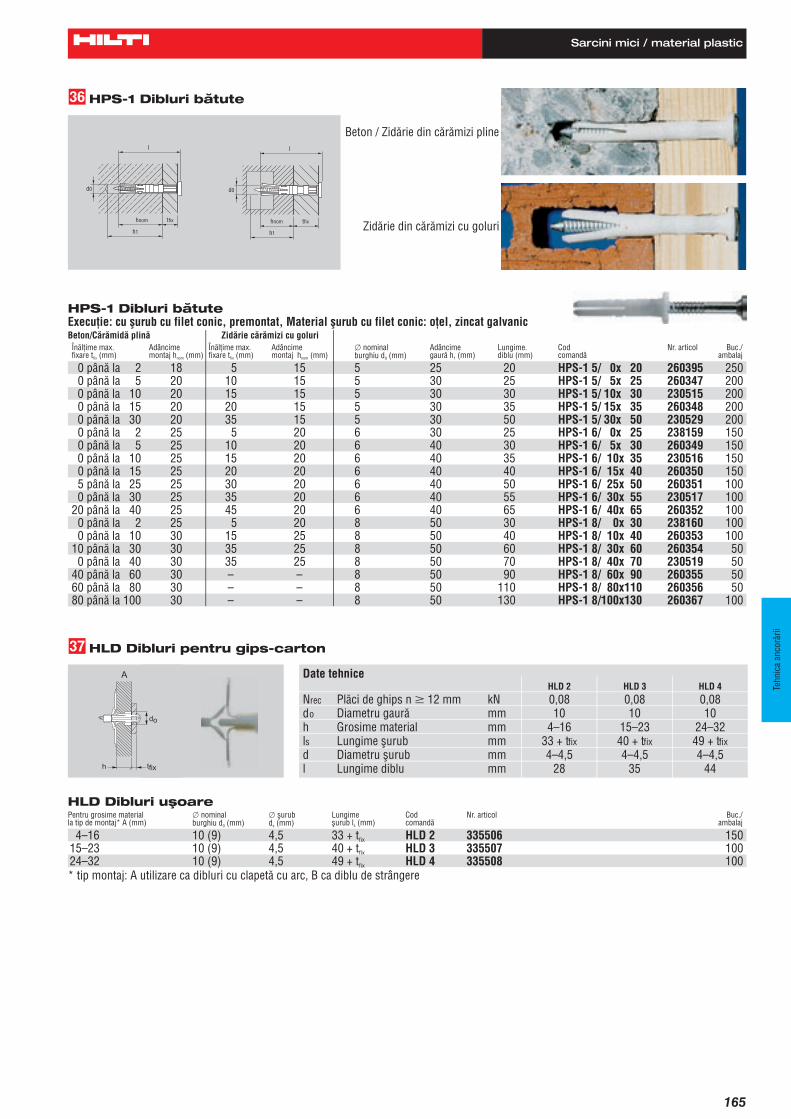
HPS-1 Dibluri bătute
Beton/Cărămidă plină Zidărie cărămizi cu goluri
0 până la 2 18 5 15 5 25 20 HPS-1 5/ 0x 20 260395 2500 până la 5 20 10 15 5 30 25 HPS-1 5/ 5x 25 260347 2000 până la 10 20 15 15 5 30 30 230515 2000 până la 15 20 20 15 5 30 35 HPS-1 5/ 15x 35 260348 2000 până la 30 20 35 15 5 30 50 HPS-1 5/ 30x 50 230529 2000 până la 2 25 5 20 6 30 25 HPS-1 6/ 0x 25 238159 1500 până la 5 25 10 20 6 40 30 260349 1500 până la 10 25 15 20 6 40 35 230516 1500 până la 15 25 20 20 6 40 40 HPS-1 6/ 15x 40 260350 1505 până la 25 25 30 20 6 40 50 HPS-1 6/ 25x 50 260351 1000 până la 30 25 35 20 6 40 55 HPS-1 6/ 30x 55 230517 100
20 până la 40 25 45 20 6 40 65 HPS-1 6/ 40x 65 260352 1000 până la 2 25 5 20 8 50 30 HPS-1 8/ 0x 30 238160 1000 până la 10 30 15 25 8 50 40 HPS-1 8/ 10x 40 260353 100
10 până la 30 30 35 25 8 50 60 HPS-1 8/ 30x 60 260354 500 până la 40 30 35 25 8 50 70 HPS-1 8/ 40x 70 230519 50
40 până la 60 30 – – 8 50 90 HPS-1 8/ 60x 90 260355 5060 până la 80 30 – – 8 50 110 HPS-1 8/ 80x110 260356 5080 până la 100 30 – – 8 50 130 HPS-1 8/100x130 260367 100
ehHPS-1 Dibluri bătute
Beton / Zidărie din cărămizi pline
Zidărie din cărămizi cu goluri
Execuţie: cu şurub cu filet conic, premontat, Material şurub cu filet conic: oţel, zincat galvanic
Înălţime max.fixare t (mm)fix
Înălţime max.fixare t (mm)fix
x nominalburghiu d (mm)0
Lungime.diblu (mm)
Adâncimemontaj h (mm)nom
Adâncimemontaj h (mm)nom
Adâncimegaură h (mm)1
Codcomandă
Buc./ambalaj
Nr. articol
HPS-1 6/ 10x 35HPS-1 6/ 5x 30
HPS-1 5/ 10x 30
HLD Dibluri uşoare Pentru grosime materialla tip de montaj* A (mm)
4–16 10 (9) 4,5 33 + tfix HLD 2 335506 15015–23 10 (9) 4,5 40 + tfix HLD 3 335507 10024–32 10 (9) 4,5 49 + tfix HLD 4 335508 100* tip montaj: A utilizare ca dibluri cu clapetă cu arc, B ca diblu de strângere
ejHLD Dibluri pentru gips-carton
Date tehniceHLD 2 HLD 3 HLD 4
Nrec Plăci de ghips n M 12 mm kN 0,08 0,08 0,08do Diametru gaură mm 10 10 10h Grosime material mm 4–16 15–23 24–32ls Lungime şurub mm 33 + tfix 40 + tfix 49 + tfixd Diametru şurub mm 4–4,5 4–4,5 4–4,5l Lungime diblu mm 28 35 44
x nominalburghiu d (mm)0
x şurubd (mm)s
Lungimeşurub l (mm)s
Codcomandă
Nr. articol Buc./ambalaj
l
tfixhnom
h1
d0
l
d0
h1
tfixhnom
165
Tehn
ica
anco
rări
i
Sarcini mici / material plastic

HGN gas concrete anchor
130 Issue 2005
Features:
- base material: lightweight concrete, gypsum panel, aerated concrete and other lightweight building materials
- through-fastening possible
- universal in application
- good keying thanks to large fins
Material:
- PA 6 polyamide, containing no heavy metals
- containing no cadmium or lead
- free of halogens and silicones
- in-place temperature range: from –40 °C to +80 °C
- temperature when setting: from –10 °C to +40 °C
Basic loading data (for a single-anchor fastening): HGN
All data on this page applies to different kinds of base material no edge distance and spacing influence
Mean ultimate resistance, Ru,m [kN]:
Anchor size HGN HGN HGN
Base material 10x100 12 14
NRu,m 2.9 2.9 4.3 PB 2 (G 2)
VRu,m 5.9 3.9 4.6
NRu,m 5.4 4.4 6.0 PB 4 (G4)
VRu,m 10.3 6.8 8.0
NRu,m - 10.4 12.4 PB 6 (G6)
VRu,m - 9.8 11.0
NRu,m 3.5 3.5 4.5 P 3.3 (GB 3.3)
VRu,m 7.0 4.7 5.5
NRu,m - 6.5 7.9 P 4.4 (GB 4.4)
VRu,m - 6.8 8.0
NRu,m - 3.7 5.0 Gypsum panel
VRu,m - 5.0 5.9
NRu,m - 3.1 4.2 Pumice concrete
VRu,m - 4.3 5.1
The compressive strengths of the base materials used to determine the data were as follows:
PB 2 = 2.5 N/mm2, 0.3 kg/dm3
PB 4 = 5.0 N/mm2, 0.5 kg/dm3
PB 6 = 7.5 N/mm2, 0.6 kg/dm3
P 3.3 = 3.5 N/mm2, 0.5 kg/dm3
P 4.4 = 5.0 N/mm2, 0.6 kg/dm3
gypsum = 7.8 N/mm2
pumice concrete = 4.7 N/mm2
HGN

HGN gas concrete anchor
Issue 2005 131
2
Design resistance, Rd [kN]:
Anchor size HGN HGN HGN
Base material 10x100 12 14
NRd 0.63 0.7 0.9 PB 2 (G 2)
VRd 1.1 0.8 1.0
NRd 1.2 1.0 1.4 PB 4 (G4)
VRd 2.0 1.3 1.75
NRd - 2.2 2.8 PB 6 (G6)
VRd - 2.0 2.24
NRd 0.8 0.9 1.1 P 3.3 (GB 3.3)
VRd 1.3 1.0 1.1
NRd - 1.4 1.7 P 4.4 (GB 4.4)
VRd - 1.3 1.75
NRd - 0.7 0.8 gypsum panel
VRd - 0.8 1.0
NRd - 0.5 0.7 pumice concrete
VRd - 0.8 1.1
Recommended load, Lrec [kN]:
Anchor size HGN HGN HGN
Base material 10x100 12 14
NRec 0.45 0.5 0.65 PB 2 (G 2)
VRec 0.8 0.6 0.7
NRec 0.85 0.75 1.0 PB 4 (G4)
VRec 1.4 0.95 1.25
NRec - 1.6 2.0 PB 6 (G6)
VRec - 1.4 1.6
NRec 0.6 0.65 0.8 P 3.3 (GB 3.3)
VRec 0.9 0.7 0.8
NRec - 1.0 1.2 P 4.4 (GB 4.4)
VRec - 0.95 1.25
NRec - 0.5 0.55 gypsum panel
VRec - 0.55 0.7
NRec - 0.35 0.5 pumice concrete
VRec - 0.6 0.8
If there is a sustained tensile load at temperatures above 40 °C, the recommended load should be reduced.

HGN gas concrete anchor
132 Issue 2005
Setting details
Anchor size
Setting details HGN 10x100 HGN 12 HGN 14*
d0 [mm] Drill bit and anchor diameter 10 12 14
h1 [mm] Min. hole depth 115 95 110
l [mm] Anchor length 100 75 85
ls [mm] Required screw length l + tfix + 5 l + tfix + 5 l + tfix + 5
d [mm] Required screw shank diameter 7 (6-8) 8-10 10-(12)
Drill bit TE-CX-10/17, TE-CX-10/22 TE-CX-12/22 TE-CX-14/22
* Recommendation: HGN 14 with 12 mm diameter screw PB 4 (G4), PB 6 (G 6): Hole of 15mm diameter.
Installation equipment
Rotary hammer (TE1, TE 2, TE5, TE6, TE6A, TE15, TE15-C, TE18-M), hammer, drill bit (See table above.) and a screwdriver (SF 100, SF 120, SD45, SU25).
Setting operations
Drill hole with drill bit. Blow out dust and
fragments.Install / tap in anchor Part fastened Drive screw into anchor.
do
l=hnomh1
d
tfix

HLC sleeve anchor
Issue 2005 103
2
Features:
- for concrete and solid masonry
- force-controlled expansion
- no rotation in hole when tightening bolt
- reliable pull-down of part fastened
Material:
- grade 6.8 HLC:
- steel galvanised to min. 5 microns
Basic loading data (for a single anchor): HLC, HLC-H, HLC-F, HLC-T, HLC-E
All data on this page applies to concrete, fcc 20 N/mm2
non-cracked concrete no edge distance and spacing influence
Characteristic resistance, Rk [kN]:
Anchor size M5 M6 M8 M10 M12 M16
Base material 6.5 8 10 12 16 20
NRk 2.5 5.0 7.5 10.0 15.0 20.0 concrete, fcc 20 N/mm2
VRk 4.0 9.0 16.0 26.0 31.5 37.5
Design resistance, Rd [kN]:
Anchor size M5 M6 M8 M10 M12 M16
Base material 6.5 8 10 12 16 20
NRd 0.7 1.4 2.1 2.8 4.2 5.6 concrete, fcc 20 N/mm2
VRd 1.1 2.5 4.5 7.3 8.8 10.5
Recommended load, Lrec [kN]:
Anchor size M5 M61) M8 M10 M12 M16
Base material 6.5 8 10 12 16 20
NRec 0.5 1.0 1.5 2.0 3.0 4.0 concrete, fcc 20 N/mm2
VRec 0.8 1.8 3.2 5.2 6.3 7.5
1) The recommended resistance (Nrec and Vrec) for HLC-E is 0.5 kN.
Note: To apply the right tightening torque (setting operations see following page) to the HLC-F, we recommend a hexagon socket wrench and for the HLC-T as well as HLC-E a screwdriver.
HLC
Concrete Fire resistance
non-cracked concrete

HLC sleeve anchor
104 Issue 2005
Setting details
Anchor size
Setting details 6.5
x25
/5
6.5
x40
/20
6.5
x60
/40
8x4
0/1
2
8x5
5/2
7
8x7
0/4
2
8x8
5/5
7
10
x40
/8
10
x50
/18
10
x60
/28
10
x80
/48
10
x10
0/6
8
12
x55
/17
12
x75
/37
12
x10
0/6
2
16
x60
/12
16
x10
0/5
2
16
x14
0/9
2
20
x80
/25
20
x11
5/6
0
20
x15
0/9
5
d [mm] Thread diameter M5 M6 M8 M10 M12 M16
d0 [mm] Drill bit diameter ¼” 8 10 12 16 20
h1 [mm] Min. hole depth 30 40 47 56 72 85
hnom [mm] Anchorage depth 20 28 32 38 48 55
tfix[mm] Fixture (fastenable) thickness
5 20 40 12 27 42 57 8 18 28 48 68 17 37 62 12 52 92 25 60 95
l [mm] Anchor length 30 45 65 46 61 76 91 48 58 68 88 108 65 85 110 72 112 152 95 130 165
lc [mm] Length under washer 25 40 60 40 55 70 85 40 50 60 80 100 55 75 100 60 100 140 80 115 150
Tinst [Nm] Tightening torque 5 8 25 40 50 80
Width across HLC 15 Sw [mm]
nut flats HLC-H 8 10 13
1719 24
dh [mm] Clearance hole 7 9 11 13 17 21
h[mm] Min. base material thickness
60 70 80 90 100 120
Drill bit TE-CX-¼”/6”
TE-CX-8/17 TE-CX-10/17 TE-CX-12/17
TE-CX-16/17
TE-C-20/22S
Installation equipment
Rotary hammer (TE1, TE 2, TE5, TE6, TE6A, TE15, TE15-C, TE18-M or TE35), a drill bit (see table above), a hammer and a torque wrench.
Setting operations
Drill hole with drill bit. Blow out dust and fragments.
Install the anchor. Apply torque.
do
l
tfix
Tinst
lc
h1h
hnom
d h

138 Hilti Product Technical Guide 10/99
Anchoring Systems
HLD Kwik-Tog 4.3.10
4.3.10.1 PRODUCT DESCRIPTIONThe Hilti Kwik-Tog is a plastic anchor designed to accept No. 8 or No. 10screws for light duty applications in hollow or solid base materials
Product Features
• Unique one piece design for easy setting • Three convenient sizes for use in a variety of hollow base materials from
1/4” drywall to block and concrete • Leg braces provide added support • Ribs on body help prevent anchor from spinning during installation • Remains mounted in the wall without screw for convenient handling,
installation and reuse
4.3.10.2 MATERIAL SPECIFICATIONS
Plastic; polypropylene for use in temperature range from-40°F to +140°F
4.3.10.3 TECHNICAL DATA
Specification Table
HLD Kwik-Tog TM 2 is specially designed for 1/2" sheetrock
S = Thickness of material being fastened
5/32" - 1/2"
3/8"
#8 or 10
11/4" + S
17/32" - 19/32"
3/8"
#8 or 10
11/4" + S
greater than13/8""
3/8"
#10 or 12
19/16" + S
HLD Kwik-Tog TM 3 is specially designed for ⁵⁄₈" sheetrock
5/18" - 3/4"
3/8"
#8 or 10
11/2" + S
3/4" - 7/8"
3/8"
#8 or 10
11/2" + S
greater than15/8"
3/8"
#10 or 12
113/16" + S
HLD Kwik-Tog TM 4
15/16" - 11/8"
3/8"
#8 or 10
17/8" + S
11/8" - 11/4"
3/8"
#8 or 10
17/8" + S
greater than2"
11/32"
#10 or 12
2 3/16" + S
HLD Kwik-Tog Allowable Loads 1
1/2" Drywall 5/8" Drywall Hollow Concrete Tension Tension Block, Tension
Description lb (N) lb (N) lb (N)HLD 2 20 (89) 25 (111) 40 (178)HLD 3 — 35 (156) 50 (222)HLD 4 — — 70 (311)
4.3.10.5 ORDERING INFORMATION
HLD Kwik-Tog Anchor ProgramBit Hollow Base Allowable Recommended Screw Size*
Item Diameter Material Load in 5/8" Drywall Hollow Solid QuantityDescription Number in. Thickness Tension, lb (kN) Base Mtl. Base Mtl. Per BoxKwik-Tog 2 (HLD2) 00063581 3/8 3/16" - 5/8" 25 (0.11) #8 or #10 #10 100Kwik-Tog 3 (HLD3) 00063582 3/8 5/8" - 7/8" 35 (0.16) #8 or #10 #10 50Kwik-Tog 4 (HLD4) 00063583 3/8 15/16" - 11/4" — #8 or #10 #10 50
4.3.10.4 INSTALLATION INSTRUCTIONS
1. Compress wingstogether.
2. Insert anchor through drilled hole.
3. Insert and tightenscrew through fixtureto expand wings.
Ld
Ld
Ld
* Screw not included
1. Based on using a safety factor of 5

HLD light-duty anchor
125
Design resistance, Rd [kN]:
Size of anchor Base Material
Anchor working principle HLD 2 HLD 3 HLD 4
Concrete: fcc = 15 N/mm2 C 0.35 0.56 0.7
Gypsum panel B 0.11 0.11 0.11
Fibre reinforced gypsum panel 12.5mm
A 0.14 - -
Fibre reinforced gypsum panel 2x12.5mm
A - 0.28 -
Asbestos cement A 0.17 0.17 0.17
Hollow brick, fired A/B 0.21 0.21 0.21
Sand-lime solid block KS 12 – 1.6 – 2DF
C 0.35 0.56 0.7
Woodwool panel A - 0.07 0.07
Basic loading data (for a single anchor): HLD
All data on this page applies to concrete: fcc = 15 N/mm2
different kinds of base material no edge distance and spacing influence table values are for tensile and shear load
Characteristic resistance, Rk [kN]:
Size of anchor Base Material
Anchor working Principle1)
HLD 2 HLD 3 HLD 4
Concrete: fcc = 15 N/mm2 C 1.25 2.0 2.5
Gypsum panel B 0.4 0.4 0.4
Fibre reinforced gypsum panel 12.5mm
A 0.30 - -
Fibre reinforced gypsum panel 2x12.5mm
A - 0.60 -
Asbestos cement A 0.6 0.6 0.6
Hollow brick, fired A/B 0.75 0.75 0.75
Sand-lime solid block KS 12 – 1.6 – 2DF
C 1.25 2.0 2.5
Woodwool panel A - 0.25 0.25 1) See setting details page 97.
Features:
- base material: virtually all existing building materials, especially panels and similar
- universal/versatile in thin-walled and solid base materials, even if they are of low strength
- bridges a large range of wall/panel thickness
- safe against rotation in hole
- excellent screw guidance
- simple setting
- setting check through noticeable increase in resistance when the screw has been driven home
Material:
- polyamide PA 6, containing no heavy metals
- without cadmium and lead
- free of halogens and silicones
- in-place temperature range: from –40 °C to +80 °C
- temperature when setting: from –10 °C to +40 °C
HLD

HLD light-duty anchor
126
Anchor size
Setting details HLD 2 HLD 3 HLD 4 HLD 2 HLD 3 HLD 4 HLD 2 HLD 3 HLD 4
d01) [mm] Drill bit diameter 9 - 10 9
h1 [mm] Hole depth - - - - - - 50 56 66
ls [mm] Screw length 33 + tfix 40 + tfix 49 + tfix 33 + tfix 40 + tfix 49 + tfix 40 + tfix 46 + tfix 56 + tfix
d [mm] Screw diameter 4 – 5 5 - 6
h [mm] Wall/panel thickness 4 – 12 15 – 19 24 – 28 12 – 16 19 – 25 28 – 32 from 35 from 42 from 50
Drill bit TE-CX-10/17, TE-CX-9/221) TE-CX-9/22
Anchor working principle A B C 1) Use a 9 mm twist drill for gypsum panel and woodwool panels, but a 10 mm drill bit for concrete.
Installation equipment
Rotary hammer (TE1, TE 2; TE5, TE6, TE6A, TE15, TE15-C, TE18-M) and a screwdriver (SF100, SF120, SD45, SU25).
Setting operations
Drill hole with drill bit. Install the HLD anchor. Drive in the screw.
A
tfixh
do
B
tfixtfix
C
do
ls
h1
Recommended load, Lrec [kN]:
Size of anchor Base Material
Anchor working principle HLD 2 HLD 3 HLD 4
Concrete: fcc = 15 N/mm2 C 0.25 0.4 0.5
Gypsum panel B 0.08 0.08 0.08
Fibre reinforced gypsum panel 12.5mm
A 0.1 - -
Fibre reinforced gypsum panel 2x12.5mm
B - 0.2 -
Asbestos cement A 0.12 0.12 0.12
Hollow brick, fired A/B 0.15 0.15 0.15
Sand-lime solid block KS 12 – 1.6 – 2DF
C 0.25 0.4 0.5
Woodwool panel A - 0.05 0.05
At temperatures above 40 °C, the recommended load should be reduced for sustained tensile loading.
Setting details
2

135Hilti Product Technical Guide 10/99
Anchoring Systems
4.3.8 HPS-1 Impact Anchor
4.3.8.1 PRODUCT DESCRIPTION
The HPS-1 Impact Anchor consists of a carbon or stainless steeldrive-screw and a plastic expansion body, which combine to forman easy to install but removable fastening for light duty applica-tions in concrete and masonry.
Product Features
• Philips drive connection is recessed in the screw head providing protection during hammering, allowing simple setting and removal
• Anchor collar and screw head form a compact unit which allows for countersinking in soft wood and solid clamping action with metal parts
• Expanding head opens in hollow base material to provide reliable keying effect • One type anchor reduces inventory, providing versatile use in brick, hollow block and concrete• Can be set with hammer or screw driver for quick and easy installation• Available with 304 Stainless Steel Nail for corrosive environments •Plastic body is temperature resistant from -40F to +176F.
Anchor can be installed from +14F to +104F. Both features allow for use in extreme climactic conditions• Suitable for through-hole fastenings to improve productivity• Removability adds to the anchors versatility
4.3.8.2 MATERIAL SPECIFICATIONS
Corrosion resistant body made of polyamide 6.6 plastic
Carbon steel drive screw material meets the requirements of AISI 1010
Carbon steel drive screw zinc plated to minimum 5 µm thickness in accordance with ASTM B633, Sc. 1, Type II
Stainless steel drive screw material meets the requirements of AISI 304
4.3.8.3 TECHNICAL DATA
HPS-1 Allowable Loads *
HPS-13/16 - 1
3/16 - 11/2BaseMaterial
AnchorHPS-11/4 - 1
HPS-11/4 - 15/81/4 - 21/161/4 - 25/8
HPS-15/16 - 15/85/16 - 21/2
HPS-15/16 - 35/85/16 - 43/8
Concrete2000 psi(13.8 MPa)
Tension lb(N)
Shear lb(N)
Tension lb(N)
Shear lb(N)
Tension lb(N)
Shear lb(N)in.
(mm)in.
(mm)
BrickMasonry
HollowConcrete Block(Normal Wt.)
Concrete
Hollow BaseRec.
Min
.Em
bed.
Dept
h
30(133)
95(422)
35(155)105
(467)50
(222)120
(534)3/4
(19)5/8
(16)
55(245)130
(578)40
(178)145
(645)55
(245)140
(623)7/8
(22)13/16
(21)
70(311)135
(600)45
(200)165
(734)60
(600)160
(712)1
(25)13/16
(21)
80(356)215
(956)45
(200)220
(979)65
(289)185
(823)13/16
(30)1
(25)
90(400)110
(489)
N/A
N/A
N/A
N/A
13/16
(30)
N/A
* Representative results of testing and a safety factor of 5.T = Tensile StrengthS= Shear Strength

136 Hilti Product Technical Guide 10/99
Anchoring Systems
HPS-1 Impact Anchor 4.3.8
4.3.8.4 INSTALLATION INSTRUCTIONS
Solid Base Materials
4.3.8.5 ORDERING INFORMATION
Carbon Steel
������
������ ������������������
������������������
���������������������������
1. Drill hole (depth = anchor length minusthickness fastened plus 1/2").
3. Set the anchor with a hammer. . . 4. . . . or set with an electric screwdriver.
2. Insert anchor.
Hollow Base Materials
Drive with a hammer or usean electric screwdriverAn accurately matchedanchor length provides optimized holding power byallowing for expansion in thefirst part of the brick or block.
HPS-1 3/16 x 1 00260347 3/16 ( 5) 3/8 ( 9) 3/16 200HPS-1 3/16 x 11/2 00260348 5/8 (15) 3/4 (19) 3/16 200HPS-1 1/4 x 1 00260368 1/8 ( 3) 3/16 ( 5) 1/4 200HPS-1 1/4 x 15/8 00260344 5/8 (15) 3/4 (19) 1/4 100HPS-1 1/4 x 21/16 00260345 1 (25) 13/16 (30) 1/4 100HPS-1 1/4 x 25/8 00260346 15/8 (41) 13/4 (44) 1/4 100HPS-1 5/16 x 15/8 00260353 3/8 ( 9) 5/8 (15) 5/16 100HPS-1 5/16 x 21/2 00260354 13/16 (30) 13/8 (35) 5/16 50HPS-1 5/16 x 35/8 00260355 23/8 (60) N/A 5/16 50HPS-1 5/16 x 43/8 00260356 33/8 (85) N/A 5/16 50
Description Item No.Fastenable Material
Thickness in Concretemax in. (mm)
Fastenable MaterialThickness in Hollow
Base Materialsmax in. (mm)
Bit Diameter
in.Box
Quantity
HPS-1 R 3/16 x 1 00260357 3/16 ( 5) 3/8 ( 9) 3/16 200HPS-1 R 3/16 x 11/2 00260358 5/8 (15) 3/4 (19) 3/16 200HPS-1 R 1/4 x 1 00230520 1/8 ( 3) 3/16 ( 5) 1/4 200HPS-1 R 1/4 x 15/8 00230521 5/8 (15) 3/4 (19) 1/4 100HPS-1 R 1/4 x 21/16 00230522 1 (25) 13/16 (30) 1/4 100HPS-1 R 1/4 x 25/8 00230523 15/8 (41) 13/4 (44) 1/4 100HPS-1 R 5/16 x 35/8 00260365 23/8 (60) N/A 5/16 50HPS-1 R 5/16 x 43/8 00260366 31/8 (85) N/A 5/16 50
Stainless Steel

HPS-1 impact anchor
131
Features:
- base material: concrete and solid or hollow brick
- ready-to-use anchor for through-fastening
- bridging of gaps due to collapsible section
- impact expansion by hammer or screwdriver
- wide product programme
- removable and adjustable with a screwdriver
Material:
- PA 6.6 polyamide, contains no heavy metals
- contains no cadmium or lead
- contains no halogens or silicones
- in-place temperature range: from –40 °C to +80 °C
- temperature when setting: from –10 °C to +40 °C
Drive screw: - steel galvanised to 5 microns
- stainless steel, A2 grade
- copper
Basic loading data (for a single anchor): HPS-1
All data on this page applies to • concrete, fcc = 20 - 45 N/mm2
• different kinds of bricks • aerated concrete• no edge distance and spacing influence
Mean ultimate resistance, Ru,m [kN]:
Anchor size
Base material
HPS-1 5/0 - HPS-1 5/15
HPS-1 6/0 – HPS-1 6/25
HPS-1 6/30 - HPS-1 6/40
HPS-1 8/0 - HPS-1 8/40
HPS-1 8/60 – HPS-1 8/100
NRu,m 1.0 1.75 1.75 2.5 2.5 Concrete, fcc= 20 – 45 N/mm2
VRu,m 2.3 3.4 2.2 5.6 3.0
NRu,m 1.0 1.75 1.75 2.5 2.5 Solid brick, Mz 20 – 1.8 – 1 NF
VRu,m 2.3 3.4 2.2 5.6 3.0
NRu,m 1.0 1.75 1.75 2.5 2.5 Sand-lime solid block, KS 12 – 1.6 – 2 DF VRu,m 2.3 3.5 1.8 3.5 2.2
NRu,m - - - - - Aerated concrete, PB 4
VRu,m 0.8 1.0 0.7 1.7 0.9
The ultimate loads were determined in holes drilled with drill bits of the minimum diameter.
HPS-1

HPS-1 impact anchor
132
l
dn
~ 2mm
tfixhnom
h1
do
Recommended load, Lrec [kN]:
Anchor size
Base material
HPS-14/0
HPS-15/0
HPS-15/5-5/15
HPS-16/0-6/25
HPS-16/30-6/40
HPS-18/0
HPS-18/10-8/40
HPS-18/60-8/100
NRec 0.05 0.1 0.15 0.25 0.25 0.3 0.4 0.4 Concrete, fcc= 20 – 45 N/mm2
VRec 0.15 0.3 0.35 0.55 0.35 0.5 0.9 0.5
NRec 0.05 0.1 0.15 0.25 0.25 0.3 0.4 0.4 Engineering brick, 12 hole, class B
VRec 0.15 0.3 0.35 0.55 0.35 0.5 0.9 0.5
NRec 0.05 0.1 0.15 0.2 0.2 0.25 0.3 0.3 Perforated brick, 3 hole cammon
VRec 0.15 0.3 0.35 0.55 0.35 0.5 0.9 0.55
NRec - - 0.08 0.15 0.15 0.2 0.25 0.25 Themalite block ,7 N, lightweight
VRec - - 0.15 0.25 0.15 0.4 0.4 0.25
Themalite block, NRec - - 0.05 0.08 0.08 - 0.12 0.12
½ N lightweight VRec - - 0.1 0.15 0.1 - 0.25 0.15
NRec - - 0.08 0.1 0.1 - 0.15 0.15 Aerated concrete, PB 4, PB 6 1)
VRec - - 0.1 0.12 0.1 - 0.3 0.2
NRec 0.05 0.1 0.15 0.2 0.2 0.25 0.35 0.35 Extruded brick, Boral 10
VRec 0.15 0.25 0.3 0.4 0.25 0.5 0.9 0.55
1) Hole drilled with TE-CX drill bit, without hammering action. If at temperatures above 40 °C loads are sustained, recommended loads should be reduced.
Setting details
Design resistance, Rd [kN]:
Anchor size
Base material
HPS-14/0
HPS-15/0
HPS-15/5-5/15
HPS-16/0-6/25
HPS-16/30-6/40
HPS-18/0
HPS-18/10-8/40
HPS-18/60-8/100
NRd 0.07 0.14 0.21 0.35 0.35 0.42 0.56 0.56 Concrete, fcc= 20 – 45 N/mm2
VRd 0.21 0.42 0.49 0.77 0.49 0.70 1.26 0.70
NRd 0.07 0.14 0.21 0.35 0.35 0.42 0.56 0.56 Engineering brick, 12 hole, class B
VRd 0.21 0.42 0.49 0.77 0.49 0.70 1.26 0.70
NRd 0.07 0.14 0.21 0.28 0.28 0.35 0.42 0.42 Perforated brick, 3 hole cammon
VRd 0.21 0.42 0.49 0.77 0.49 0.7 1.26 0.77
NRd - - 0.11 0.21 0.21 0.28 0.35 0.35 Themalite block, 7 N lightweight
VRd - - 0.21 0.35 0.21 0.56 0.56 0.35
Themalite block, NRd - - 0.07 0.11 0.11 - 0.17 0.17
½ N lightweight VRd - - 0.14 0.21 0.14 - 0.35 0.21
NRd - - 0.11 0.14 0.14 - 0.21 0.21 Aerated concrete, PB 4, PB 6 1)
VRd - - 0.14 0.17 0.14 - 0.42 0.28
NRd 0.07 0.14 0.21 0.28 0.28 0.35 0.49 0.49 Extruded brick, Boral 10
VRd 0.21 0.35 0.42 0.56 0.35 0.7 1.26 0.77
2

HPS-1 impact anchor
131
Features:
- base material: concrete and solid or hollow brick
- ready-to-use anchor for through-fastening
- bridging of gaps due to collapsible section
- impact expansion by hammer or screwdriver
- wide product programme
- removable and adjustable with a screwdriver
Material:
- PA 6.6 polyamide, contains no heavy metals
- contains no cadmium or lead
- contains no halogens or silicones
- in-place temperature range: from –40 °C to +80 °C
- temperature when setting: from –10 °C to +40 °C
Drive screw: - steel galvanised to 5 microns
- stainless steel, A2 grade
- copper
Basic loading data (for a single anchor): HPS-1
All data on this page applies to • concrete, fcc = 20 - 45 N/mm2
• different kinds of bricks • aerated concrete• no edge distance and spacing influence
Mean ultimate resistance, Ru,m [kN]:
Anchor size
Base material
HPS-1 5/0 - HPS-1 5/15
HPS-1 6/0 – HPS-1 6/25
HPS-1 6/30 - HPS-1 6/40
HPS-1 8/0 - HPS-1 8/40
HPS-1 8/60 – HPS-1 8/100
NRu,m 1.0 1.75 1.75 2.5 2.5 Concrete, fcc= 20 – 45 N/mm2
VRu,m 2.3 3.4 2.2 5.6 3.0
NRu,m 1.0 1.75 1.75 2.5 2.5 Solid brick, Mz 20 – 1.8 – 1 NF
VRu,m 2.3 3.4 2.2 5.6 3.0
NRu,m 1.0 1.75 1.75 2.5 2.5 Sand-lime solid block, KS 12 – 1.6 – 2 DF VRu,m 2.3 3.5 1.8 3.5 2.2
NRu,m - - - - - Aerated concrete, PB 4
VRu,m 0.8 1.0 0.7 1.7 0.9
The ultimate loads were determined in holes drilled with drill bits of the minimum diameter.
HPS-1

HPS-1 impact anchor
132
l
dn
~ 2mm
tfixhnom
h1
do
Recommended load, Lrec [kN]:
Anchor size
Base material
HPS-14/0
HPS-15/0
HPS-15/5-5/15
HPS-16/0-6/25
HPS-16/30-6/40
HPS-18/0
HPS-18/10-8/40
HPS-18/60-8/100
NRec 0.05 0.1 0.15 0.25 0.25 0.3 0.4 0.4 Concrete, fcc= 20 – 45 N/mm2
VRec 0.15 0.3 0.35 0.55 0.35 0.5 0.9 0.5
NRec 0.05 0.1 0.15 0.25 0.25 0.3 0.4 0.4 Engineering brick, 12 hole, class B
VRec 0.15 0.3 0.35 0.55 0.35 0.5 0.9 0.5
NRec 0.05 0.1 0.15 0.2 0.2 0.25 0.3 0.3 Perforated brick, 3 hole cammon
VRec 0.15 0.3 0.35 0.55 0.35 0.5 0.9 0.55
NRec - - 0.08 0.15 0.15 0.2 0.25 0.25 Themalite block ,7 N, lightweight
VRec - - 0.15 0.25 0.15 0.4 0.4 0.25
Themalite block, NRec - - 0.05 0.08 0.08 - 0.12 0.12
½ N lightweight VRec - - 0.1 0.15 0.1 - 0.25 0.15
NRec - - 0.08 0.1 0.1 - 0.15 0.15 Aerated concrete, PB 4, PB 6 1)
VRec - - 0.1 0.12 0.1 - 0.3 0.2
NRec 0.05 0.1 0.15 0.2 0.2 0.25 0.35 0.35 Extruded brick, Boral 10
VRec 0.15 0.25 0.3 0.4 0.25 0.5 0.9 0.55
1) Hole drilled with TE-CX drill bit, without hammering action. If at temperatures above 40 °C loads are sustained, recommended loads should be reduced.
Setting details
Design resistance, Rd [kN]:
Anchor size
Base material
HPS-14/0
HPS-15/0
HPS-15/5-5/15
HPS-16/0-6/25
HPS-16/30-6/40
HPS-18/0
HPS-18/10-8/40
HPS-18/60-8/100
NRd 0.07 0.14 0.21 0.35 0.35 0.42 0.56 0.56 Concrete, fcc= 20 – 45 N/mm2
VRd 0.21 0.42 0.49 0.77 0.49 0.70 1.26 0.70
NRd 0.07 0.14 0.21 0.35 0.35 0.42 0.56 0.56 Engineering brick, 12 hole, class B
VRd 0.21 0.42 0.49 0.77 0.49 0.70 1.26 0.70
NRd 0.07 0.14 0.21 0.28 0.28 0.35 0.42 0.42 Perforated brick, 3 hole cammon
VRd 0.21 0.42 0.49 0.77 0.49 0.7 1.26 0.77
NRd - - 0.11 0.21 0.21 0.28 0.35 0.35 Themalite block, 7 N lightweight
VRd - - 0.21 0.35 0.21 0.56 0.56 0.35
Themalite block, NRd - - 0.07 0.11 0.11 - 0.17 0.17
½ N lightweight VRd - - 0.14 0.21 0.14 - 0.35 0.21
NRd - - 0.11 0.14 0.14 - 0.21 0.21 Aerated concrete, PB 4, PB 6 1)
VRd - - 0.14 0.17 0.14 - 0.42 0.28
NRd 0.07 0.14 0.21 0.28 0.28 0.35 0.49 0.49 Extruded brick, Boral 10
VRd 0.21 0.35 0.42 0.56 0.35 0.7 1.26 0.77
2
HPS-1 impact anchor
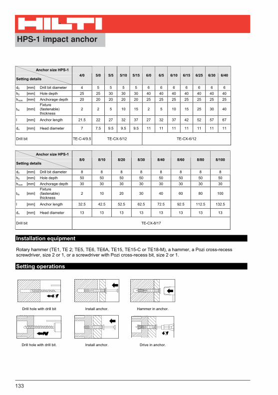
133
Anchor size HPS-1
Setting details 4/0 5/0 5/5 5/10 5/15 6/0 6/5 6/10 6/15 6/25 6/30 6/40
d0 [mm] Drill bit diameter 4 5 5 5 5 6 6 6 6 6 6 6
h0 [mm] Hole depth 25 25 30 30 30 40 40 40 40 40 40 40
hnom [mm] Anchorage depth 20 20 20 20 20 25 25 25 25 25 25 25
tfix [mm]Fixture(fastenable)thickness
2 2 5 10 15 2 5 10 15 25 30 40
l [mm] Anchor length 21.5 22 27 32 37 27 32 37 42 52 57 67
dn [mm] Head diameter 7 7.5 9.5 9.5 9.5 11 11 11 11 11 11 11
Drill bit TE-C-4/9.5 TE-CX-5/12 TE-CX-6/12
Anchor size HPS-1
Setting details 8/0 8/10 8/20 8/30 8/40 8/60 8/80 8/100
d0 [mm] Drill bit diameter 8 8 8 8 8 8 8 8
h0 [mm] Hole depth 50 50 50 50 50 50 50 50
hnom [mm] Anchorage depth 30 30 30 30 30 30 30 30
tfix [mm]Fixture(fastenable)thickness
2 10 20 30 40 60 80 100
l [mm] Anchor length 32.5 42.5 52.5 62.5 72.5 92.5 112.5 132.5
dn [mm] Head diameter 13 13 13 13 13 13 13 13
Drill bit TE-CX-8/17
Installation equipment
Rotary hammer (TE1, TE 2; TE5, TE6, TE6A, TE15, TE15-C or TE18-M), a hammer, a Pozi cross-recess screwdriver, size 2 or 1, or a screwdriver with Pozi cross-recess bit, size 2 or 1.
Setting operations
Drill hole with drill bit Install anchor. Hammer in anchor.
������
����
Drill hole with drill bit. Install anchor. Drive in anchor.

139Hilti Product Technical Guide 10/99
Anchoring Systems
HSP/HFP Drywall Anchor4.3.11
4.3.11.1 PRODUCT DESCRIPTION
The Hilti HSP/HFP Drywall Anchor is a self-drilling anchordesigned for fast and reliable fastenings in drywall.
Product Features• Shark tooth design for correct positioning and quick installation • Cuts its own thread - no predrilling necessary • One Hilti bit for anchor and screw setting • Can be set with electric or standard screwdriver for quick and
simple installation • Removability adds to the anchor’s versatility • Available in non-conductive nylon or zinc for a variety of
applications • Available with and without screws for your convenience
4.3.11.2 MATERIAL SPECIFICATIONS
Zinc
Nylon
4.3.11.3 TECHNICAL DATA
HSP/HFP Drywall Anchor Allowable Loads 1
4.3.11.4 INSTALLATION INSTRUCTIONS
4.3.11.5 ORDERING INFORMATION
HDS Drywall Anchor Program
Gypsum Wall Board1/2" 5/8"
HSP with Screw Tension Shear Tension Shear# 8 x 1 3/16 lb (N) lb (N) lb (N) lb (N)
HFP with Screw 15 40 22 60# 8 x 1 (70) (180) (100) (270)
Push the teeth of theanchor into the drywallpanel.
Drive the anchor(clockwise rotation)until it lies flush withthe wall.
Drive and tighten thescrew with the Hilti bit.
Item no. Description Anchor lenght ld (in.) Screw dia. (in.) Quantity Remarks
00332682 HSP 1 1/2 # 8 10000332683 HSP-S 1 1/2 # 8 100 Delivered with 100 screws, # 8 x 1 3/16˝ 00333557 HSP-1/4” THREAD 1 1/2 –– 100 Delivered with one bit D-B SQ HSP-G (00332689)00332686 HFP 1 1/8 # 8 10000332687 HFP-S 1 1/8 # 8 100 Delivered with 100 screws, # 8 x 1˝00332688 D-B PH2 HSP/HFP –– –– 500332689 D-B SQ HSP-G –– –– 5
1. Based on using a safety factor of 5
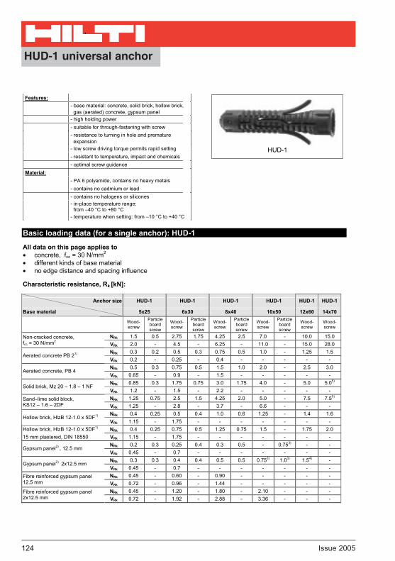
HUD-1 universal anchor
124 Issue 2005
Features:
- base material: concrete, solid brick, hollow brick, gas (aerated) concrete, gypsum panel
- high holding power
- suitable for through-fastening with screw
- resistance to turning in hole and premature expansion
- low screw driving torque permits rapid setting
- resistant to temperature, impact and chemicals
- optimal screw guidance
Material:
- PA 6 polyamide, contains no heavy metals
- contains no cadmium or lead
- contains no halogens or silicones
- in-place temperature range: from –40 °C to +80 °C
- temperature when setting: from –10 °C to +40 °C
Basic loading data (for a single anchor): HUD-1
All data on this page applies to concrete, fcc = 30 N/mm2
different kinds of base material no edge distance and spacing influence
Characteristic resistance, Rk [kN]:
Anchor size HUD-1 HUD-1 HUD-1 HUD-1 HUD-1 HUD-1
Base material 5x25 6x30 8x40 10x50 12x60 14x70
Wood- screw
Particleboardscrew
Wood- screw
Particleboardscrew
Wood- screw
Particleboardscrew
Wood- screw
Particleboardscrew
Wood-screw
Wood-screw
NRk 1.5 0.5 2.75 1.75 4.25 2.5 7.0 - 10.0 15.0 Non-cracked concrete, fcc = 30 N/mm2
VRk 2.0 - 4.5 - 6.25 - 11.0 - 15.0 28.0
NRk 0.3 0.2 0.5 0.3 0.75 0.5 1.0 - 1.25 1.5 Aerated concrete PB 21)
VRk 0.2 - 0.25 - 0.4 - - - - -
NRk 0.5 0.3 0.75 0.5 1.5 1.0 2.0 - 2.5 3.0 Aerated concrete, PB 4
VRk 0.65 - 0.9 - 1.5 - - - - -
NRk 0.85 0.3 1.75 0.75 3.0 1.75 4.0 - 5.0 5.05)
Solid brick, Mz 20 – 1.8 – 1 NF VRk 1.2 - 1.5 - 2.2 - - - - -
NRk 1.25 0.75 2.5 1.5 4.25 2.0 5.0 - 7.5 7.55)Sand–lime solid block,KS12 – 1.6 – 2DF VRk 1.25 - 2.8 - 3.7 - 6.6 - - -
NRk 0.4 0.25 0.5 0.4 1.0 0.6 1.25 - 1.4 1.6 Hollow brick, HlzB 12-1.0 x 5DF1)
VRk 1.15 - 1.75 - - - - - - -
Hollow brick, HlzB 12-1.0 x 5DF1) NRk 0.4 0.25 0.75 0.5 1.25 0.75 1.5 - 1.75 2.0
15 mm plastered, DIN 18550 VRk 1.15 - 1.75 - - - - - - -
NRk 0.2 0.3 0.25 0.4 0.3 0.5 - 0.753) - - Gypsum panel2) , 12.5 mm
VRk 0.45 - 0.7 - - - - - - -
NRk 0.3 0.3 0.4 0.4 0.5 0.5 0.753) 1.03) 1.54) - Gypsum panel2) 2x12.5 mm
VRk 0.45 - 0.7 - - - - - - -
NRk 0.45 - 0.60 - 0.90 - - - - - Fibre reinforced gypsum panel 12.5 mm VRk 0.72 - 0.96 - 1.44 - - - - -
NRk 0.45 - 1.20 - 1.80 - 2.10 - - - Fibre reinforced gypsum panel 2x12.5 mm VRk 0.72 - 1.92 - 2.88 - 3.36 - - -
HUD-1

HUD-1 universal anchor
Issue 2005 125
Anchor size HUD-1 HUD-1 HUD-1 HUD-1 HUD-1 HUD-1
Base material 5x25 6x30 8x40 10x50 12x60 14x70
Wood- screw
Particleboardscrew
Wood- screw
Particleboardscrew
Wood- screw
Particleboardscrew
Wood- screw
Particleboardscrew
Wood- screw
Wood- screw
NRec 0.3 0.1 0.55 0.35 0.85 0.5 1.4 - 2.0 3.0 Non-cracked concrete, fcc = 30 N/mm2
VRec 0.4 - 0.9 - 1.25 - 2.2 - 3.0 5.6
NRec 0.06 0.04 0.1 0.06 0.15 0.1 0.2 - 0.25 0.3 Aerated concrete, PB 21)
VRec 0.04 - 0.05 - 0.08 - - - - -
NRec 0.1 0.06 0.15 0.1 0.3 0.2 0.4 - 0.5 0.6 Aerated concrete, PB 4
VRec 0.13 - 0.18 - 0.3 - - - - -
NRec 0.17 0.06 0.35 0.15 0.6 0.35 0.8 - 1.0 1.05)
Solid brick, Mz 20 – 1.8 – 1 NF VRec 0.24 - 0.3 - 0.44 - - - - -
NRec 0.25 0.15 0.5 0.3 0.85 0.4 1.0 - 1.5 1.55)Sand–lime solid block,KS 12 – 1.6 – 2 DF VRec 0.25 - 0.56 - 0.74 - 1.32 - - -
NRec 0.08 0.05 0.1 0.08 0.2 0.12 0.25 - 0.28 0.32 Hollow brick, HlzB 12-1.0 x 5DF1)
VRec 0.23 - 0.35 - - - - - - -
Hollow brick, HlzB 12-1.0 x 5DF1) NRec 0.08 0.05 0.15 0.1 0.25 0.15 0.3 - 0.35 0.4
15 mm plastered DIN 18550 VRec 0.23 - 0.35 - - - - - - -
NRec 0.04 0.06 0.05 0.08 0.06 0.1 - 0.153) - - Gypsum panel2) , 12.5 mm
VRec 0.09 - 0.14 - - - - - - -
NRec 0.06 0.06 0.08 0.08 0.1 0.1 0.153) 0.23) 0.34) - Gypsum panel2) , 2 x12.5 mm
VRec 0.09 - 0.14 - - - - - - -
NRec 0.15 - 0.20 - 0.30 - - - - - Fibre reinforced gypsum panel 12.5 mm VRec 0.24 - 0.32 - 0.48 - - - - -
NRec 0.15 - 0.40 - 0.60 - 0.70 - - - Fibre reinforced gypsum panel 2x12.5 mm VRec 0.24 - 0.64 - 0.96 - 1.12 - - -
Recommended Load, Lrec [kN]:
Anchor size HUD-1 HUD-1 HUD-1 HUD-1 HUD-1 HUD-1
Base material 5x25 6x30 8x40 10x50 12x60 14x70
Wood- screw
Particleboardscrew
Wood- screw
Particleboardscrew
Wood- screw
Particleboardscrew
Wood- screw
Particleboardscrew
Wood-screw
Wood-screw
NRd 0.42 0.14 0.77 0.5 1.2 0.7 2.0 - 2.8 4.2 Non-cracked concrete, fcc = 30 N/mm2
VRd 0.6 - 1.3 - 1.75 - 3.1 - 4.2 7.8
NRd 0.08 0.06 0.14 0.08 0.21 0.14 0.28 - 0.35 0.42 Aerated concrete, PB 21)
VRd 0.06 - 0.07 - 0.11 - - - - -
NRd 0.14 0.08 0.21 0.14 0.4 0.3 0.6 - 0.7 0.8 Aerated concrete, PB4
VRd 0.2 - 0.3 - 0.4 - - - - -
NRd 0.24 0.08 0.5 0.21 0.84 0.5 1.1 - 1.4 1.45)
Solid brick, Mz 20 – 1.8 – 1 NF VRd 0.34 - 0.4 - 0.62 - - - - -
NRd 0.35 0.21 0.7 0.42 1.2 0.56 1.4 - 2.1 2.15)Sand–lime solid block,KS 12 – 1.6 – 2DF VRd 0.35 - 0.8 - 1.0 - 1.8 - - -
NRd 0.11 0.07 0.14 0.11 0.3 0.17 0.35 - 0.4 0.5 Hollow brick, HlzB 12-1.0 x 5DF1)
VRd 0.3 - 0.5 - - - - - - -
Hollow brick, HlzB 12-1.0 x 5DF1) NRd 0.11 0.07 0.2 0.14 0.35 0.21 0.4 - 0.5 0.6
15 mm plastered, DIN 18550 VRd 0.32 - 0.5 - - - - - - -
NRd 0.06 0.08 0.07 0.11 0.08 0.14 - 0.213) - - Gypsum panel2) , 12.5 mm
VRd 0.13 - 0.2 - - - - - - -
NRd 0.08 0.08 0.11 0.11 0.14 0.14 0.213) 0.283) 0.424) - Gypsum panel2) , 2 x12.5 mm
VRd 0.13 0.2 - - - -
NRd 0.21 - 0.28 - 0.42 - - - - - Fibre reinforced gypsum panel 12.5 mm VRd 0.33 - 0.45 - 0.67 - - - - -
NRd 0.21 - 0.56 - 0.84 - 0.98 - - - Fibre reinforced gypsum panel 2x12.5 mm VRd 0.33 - 0.90 - 1.34 - 1.57 - - -
Design resistance, Rd [kN]:
2

HUD-1 universal anchor
126 Issue 2005
����������������������������������������������������������������������������������������
����������������������������������������������������������������������������������������
���������������
������������
����������������������������������������������������������������������������������������
��������������������
���������������� �
��
Drill hole with drill bit. Install anchor. Drive screw into anchor.
Drill hole with drill bit. Install anchor. Drive screw into anchor.
1) Drilling (TE-CX, TE-C) without hammering 2) Drilling: Twist drill 3) Only with screw 6 mm diameter 4) Only with screw 8 mm diameter 5) Only with screw 10 mm diameter
Setting details
Anchor size
Setting details
HUD –1 5x25
HUD-1 6x30
HUD-18x40
HUD-1 10x50
HUD-1 12x60
HUD-114x70
d0 [mm] Drill bit diameter 5 6 8 10 12 14
h1 [mm] Min. hole depth 35 40 55 65 80 90
ld [mm] Anchor length 25 30 40 50 60 70
tfix [mm] Max. fixture thickness depends on screw lengths
Recommended woodscrew type SK/RK SK/RK SK/RK SK/RK/6K SK/RK/6K 6K
d [mm] Woodscrew diameter 3.5 - 4 4.5 - 5 5 – 6 7 - 8 8 - 10 10 - 12
Screw length ld + tfix + 5 mm
Drill bit TE-CX-5/12 TE-CX-6/12 TE-CX-8/17 TE-CX-10/17 TE-CX-12/17 TE-CX-14/17
Edge distances and spacings:
Anchor size HUD-15x25
HUD-16x30
HUD-18x40
spacing [mm] 50 60 80 edge distance [mm] 40 40 40
Installation equipment
Rotary hammer (TE1, TE 2, TE5, TE6, TE6, TE6A, TE15, TE15-C or TE18-M), a drill bit (See table above.) and a screwdriver (SF 100, SF 120, SD45 or SU25).
Setting operations
ld h1
do
5mm + ld
tfix

HUD-L universal anchor
Issue 2005 127
2
Features:
- base material: concrete, solid brick, hollow brick, aerated concrete, gypsum panel
- special length to cope with thick hollow brick / masonry
- suitable for through-fastening with screw
- resistance to turning in hole and premature expansion
- low screw driving torque permits rapid setting
- resistant to temperature, impact and chemicals
- optimised screw guidance
Material:
- PA 6 polyamide, contains no heavy metals
- contains no cadmium or lead
- contains no halogens and silicones
- in-place temperature range: from –40 °C to +80 °C
- Temperature when setting: from –10 °C to +40 °C
Basic loading data (for a single anchor): HUD-L
All data on this page applies to concrete: fcc = 30 N/mm2
different kinds of base material no edge distance and spacing influence
Characteristic resistance, Rk [kN]:
Anchor size HUD-L 6x50 HUD-L 8x60 HUD-L 10x70
Base material Woodscrew 5 mm Woodscrew 6 mm Woodscrew 8 mm
NRk 4.5 6.5 9.0 Non- cracked concrete1)
f cc = 30 N/mm2
VRk 5.0 7.5 12.5
NRk 0.6 1.25 2.0 Aerated concrete, PB 22)
VRk 1.0 1.75 3.5
NRk 1.2 2.5 3.5 Aerated concrete, PB 4
VRk - - -
NRk 2.5 4.0 7.0 Solid brick, Mz 20 – 1.8 – 1 NF
VRk - - -
Sand–lime solid block, NRk 2.75 4.5 7.5
KS 12 – 1.6 – 2PDF VRk - - -
Sand–lime hollow block, NRk 1.25 1.5 2.0
KSL 12 – 1.4 – 2DF VRk - - -
NRk 0.75 1.0 1.5 Hollow brick, HlzB 12-1.0 - 5DF2)
VRk 2.0 3.5 6.5
Hollow brick, HlzB 12-1.0 - 5DF2) NRk 0.75 1.0 1.5
15 mm plastered, DIN 18550 VRk 2.0 3.5 6.5
NRk 0.5 0.75 0.63)Gypsum panel2) , 2x12.5 mm DIN 18180 VRk 0.75 1.75 -
NRk 1.50 1.80 2.10 Fibre reinforced gypsum panel 2x12.5mm VRk 2.40 2.90 3.36
HUD-L
HUD-L universal anchor
128 Issue 2005
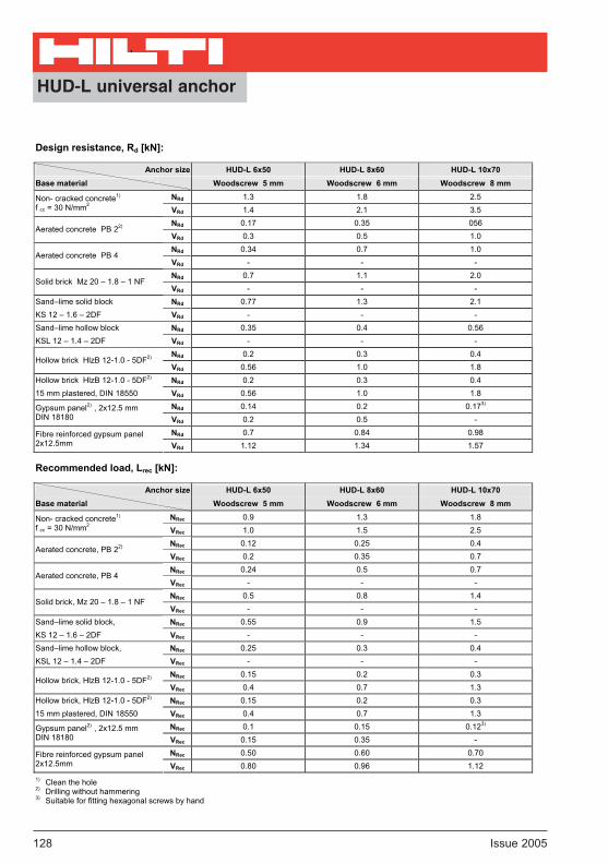
Design resistance, Rd [kN]:
Anchor size HUD-L 6x50 HUD-L 8x60 HUD-L 10x70
Base material Woodscrew 5 mm Woodscrew 6 mm Woodscrew 8 mm
NRd 1.3 1.8 2.5 Non- cracked concrete1)
f cc = 30 N/mm2VRd 1.4 2.1 3.5
NRd 0.17 0.35 056 Aerated concrete PB 22)
VRd 0.3 0.5 1.0
NRd 0.34 0.7 1.0 Aerated concrete PB 4
VRd - - -
NRd 0.7 1.1 2.0 Solid brick Mz 20 – 1.8 – 1 NF
VRd - - -
Sand–lime solid block NRd 0.77 1.3 2.1
KS 12 – 1.6 – 2DF VRd - - -
Sand–lime hollow block NRd 0.35 0.4 0.56
KSL 12 – 1.4 – 2DF VRd - - -
NRd 0.2 0.3 0.4 Hollow brick HlzB 12-1.0 - 5DF2)
VRd 0.56 1.0 1.8
Hollow brick HlzB 12-1.0 - 5DF2) NRd 0.2 0.3 0.4
15 mm plastered, DIN 18550 VRd 0.56 1.0 1.8
NRd 0.14 0.2 0.173)Gypsum panel2) , 2x12.5 mm DIN 18180 VRd 0.2 0.5 -
NRd 0.7 0.84 0.98 Fibre reinforced gypsum panel 2x12.5mm VRd 1.12 1.34 1.57
Recommended load, Lrec [kN]:
Anchor size HUD-L 6x50 HUD-L 8x60 HUD-L 10x70
Base material Woodscrew 5 mm Woodscrew 6 mm Woodscrew 8 mm
NRec 0.9 1.3 1.8 Non- cracked concrete1)
f cc = 30 N/mm2VRec 1.0 1.5 2.5
NRec 0.12 0.25 0.4 Aerated concrete, PB 22)
VRec 0.2 0.35 0.7
NRec 0.24 0.5 0.7 Aerated concrete, PB 4
VRec - - -
NRec 0.5 0.8 1.4 Solid brick, Mz 20 – 1.8 – 1 NF
VRec - - -
Sand–lime solid block, NRec 0.55 0.9 1.5
KS 12 – 1.6 – 2DF VRec - - -
Sand–lime hollow block, NRec 0.25 0.3 0.4
KSL 12 – 1.4 – 2DF VRec - - -
NRec 0.15 0.2 0.3 Hollow brick, HlzB 12-1.0 - 5DF2)
VRec 0.4 0.7 1.3
Hollow brick, HlzB 12-1.0 - 5DF2) NRec 0.15 0.2 0.3
15 mm plastered, DIN 18550 VRec 0.4 0.7 1.3
NRec 0.1 0.15 0.123)Gypsum panel2) , 2x12.5 mm DIN 18180 VRec 0.15 0.35 -
NRec 0.50 0.60 0.70 Fibre reinforced gypsum panel 2x12.5mm VRec 0.80 0.96 1.12
1) Clean the hole 2) Drilling without hammering 3) Suitable for fitting hexagonal screws by hand

HUD-L universal anchor
Issue 2005 129
2
Setting details
Anchor size
Setting details HUD-L 6x50 HUD-L 8x60 HUD-L 10x70
d0 [mm] Drill bit diameter 6 8 10
h1 [mm] Min. hole depth 70 80 90
ld [mm] Anchor length 50 60 70
Recommended woodscrew diameter common woodscrews and particle board screws
tfix [mm] Max. fixture thickness depends on screw length
d [mm] Woodscrew diameter 4.5 - 5 5 - 6 7 - 8
ld [mm]Req. length of screw engagement in base material
55 65 75
Drill bit TE-CX-6/17 TE-CX-8/17 TE-CX-10/22
Installation equipment
Rotary hammer (TE1, TE 2, TE5, TE6, TE6A, TE15, TE15-C or TE18-M), a drill bit (See table above.) and a screwdriver (SF 100, SF 120, SD45 or SU25).
Setting operations
Drill hole with drill bit. Install anchor. Put part being fastened in place and drive screw into anchor.
Drill hole with drill bit. Put part being fastened in place and
install anchor. Drive screw into anchor.
��������������������������������������������������������������������������������������������������������������������������������������������������������������������������������
��������������������
��������������������
������������
������������
h1
ld
5 mm + ld + tfixt fix
do

HUS screw anchor
142 Issue 2005
Features:
- base material: concrete, gas (aerated) concrete,
sand-lime blocks, hollow bricks,
- removable
- stand-off fastening
- small edge distances and spacing
- easy to drive using tangential impact screwdriver
- approved for suspended ceilings
Material:
- grade 10.9, 19MnB4, zinc plated to 5 microns,
- yellow chromated
Basic loading data (for a single anchor): HUS, HUS-S, HUS-H, HUS-A
All data on this page applies to concrete: C20/25 sand-lime blocks, aerated concrete, hollow bricks
Characteristic resistance, Rk [kN]:
Base material Tensile load, NRk [kN] Shear load ,VRk [kN], for edge distance
60 mm 30 mm
Concrete, C20/25 5.0 8.0 2.5
KS sand-lime block 5.0 5.5 2.0
Hlz 0.8/121) hollow brick 0.5 2.0 1.0
PB2/PB42) aerated concrete 1.0 1.5 0.5
PB6 aerated concrete 1.0 3.0 1.0
Design resistance, Rd [kN]:
Base material Tensile load, NRd [kN] Shear load, VRd [kN], for edge distance
60 mm 30 mm
Concrete, C20/25 1.4 2.2 0.7
KS sand-lime block 1.4 1.5 0.6
Hlz 0.8/121) hollow brick 0.14 0.6 0.3
PB2/PB42) aerated concrete 0.3 0.4 0.14
PB6 aerated concrete 0.3 0.8 0.3 1) The holes must be drilled using rotary action only (no hammering action). 2) Holes must not be drilled in PB2/PB4 gas (aerated) concrete (not permitted).
Note:Data is available on request for fastenings in other base materials or when other drill bits are used. Alternatively, on-site tests must be carried out. When tightening the screw anchor in soft base materials and in perforated brick, care must be taken not to apply too much torque. If the screw anchor is overtightened, the fastening may become unusable.
HUS
HUS-S
HUS-H
HUS-A
ConcreteSmall edge
distance/ spacing Fire resistance IFT assessment

HUS screw anchor
Issue 2005 143
2
Recommended load, Lrec [kN]:
Base material Tensile load, Nrec [kN] Shear load, Vrec [kN], for edge distance
60 mm 30 mm
Concrete, C20/25 1.0 1.6 0.5
KS sand-lime block 1.0 1.1 0.4
Hlz 0.8/121) hollow brick 0.1 0.4 0.2
PB2/PB42) aerated concrete 0.2 0.3 0.1
PB6 aerated concrete 0.2 0.6 0.2 1) The holes must be drilled using rotary action only (no hammering action). 2) Holes must not be drilled in PB2/PB4 gas (aerated) concrete (not permitted).
Setting details
ltfixhnom
dh
h0
d0
h0dh
l
d0
tfixhnom
HUS HUS-S
h0
d0
tfix
dh
hnom
l
h0
hnom
l
d0
lG
dG
HUS-H HUS-A

HUS screw anchor
144 Issue 2005
Anchor size Aerated concrete
Setting detailsConcrete Solid brick Hollow brick
PB2/PB4 PB6
d0 [mm] Drill bit diameter 6 6 6 - 6
h0 [mm] Hole depth1), 2) 40 50 70 - 60
hnom [mm] Anchorage depth2) 34 44 64 64 64
tfix [mm] Fixture thickness l - hnom
HUS-A M8 18 lG [mm] Length of metric thread
HUS-A M10 21
Stand-off fastening 6.2 dh [mm] Through hole
Tighten component against base material 8 – 8.5
HUS 35 - 220
HUS-S 100 - 220
HUS-H 35 - 120 l [mm] Anchor length
HUS-A 65.5 – 91.5
Drill bit TE-CX-6/17 TKI-S-6/20 - TE-CX-6/17TKI-S-6/20
Accessories HUS: S-B TXI 40 bit; HUS-S: S-B TXI 30 bit;
HUS-H: S-NSD 13 L socket or S-B TXI 40 bit; HUS-A: S-NS 13 3/8 L socket1) When a hole is drilled in a downward direction, we recommend that the drilling depth is increased by 10 mm as the drilling dust and fragments are difficult to blow out and additional dust and fragments are created when the screw anchor is driven in.2) If a layer of plaster exists, the drilling depth, setting depth and screw anchor length must be increased by the thickness of the plaster layer.
Installation equipment
Rotary hammer (TE1, TE 2, TE5, TE6, TE6A, TE15-C or TE18-M), a screwdriver (TKI 2500, TCI 12), a drill bit and a bit (See table above.) and a blow-out bump.
Setting operations
HUS:
Drill hole with drill bit. Blow out dust and fragments. Install anchor with an electric
screwdriver.
HUS-S:
Drill hole with drill bit. Blow out dust and fragments. Install anchor with an electric
screwdriver.

HUS screw anchor
Issue 2005 145
2
Setting operations
HUS-H:
Drill hole with drill bit. Blow out dust and fragments. Install anchor with an electric
screwdriver.
HUS-A:
Drill hole with drill bit. Blow out dust and fragments. Install anchor with an electric
screwdriver.