lucrare de diplomĂ grafuri de context în asistarea ... · grafuri de context în asistarea...
TRANSCRIPT

Universitatea POLITEHNICA din Bucures,ti
Facultatea de Automatică s, i Calculatoare,Departamentul de Calculatoare
LUCRARE DE DIPLOMĂ
Grafuri de context în asistareautilizatorilor în activităt, i zilnice
Conducător S, tiint, ific: Autor:S, .l.dr.ing. Andrei Olaru Cătălin Badea
Bucures,ti, 2014
University POLITEHNICA of Bucharest
Faculty of Automatic Control and Computers,Computer Science and Engineering Department
BACHELOR THESIS
Using context graphs to help users intheir daily activities
Scientific Adviser: Author:S, .l.dr.ing. Andrei Olaru Cătălin Badea
Bucharest, 2014
I would like to thank my supervisor, Andrei Olaru,for the support and guidance he offered me throughout
the development of this project.
Abstract
In the field of Ambient Intelligence, context-awareness has recently gained a lot of traction as aresearch topic. Context-awareness can be defined as the property of a device to use contextualinformation in its interraction to the user. One of the most basic types of context is GPSlocation. The notion of context, however, can be extended to include any information thatmight be relevant to the interaction with the user. To take advantage of this information, theproblem of accurately representing user context must be solved.
A solution to this problem is using graphs as the base structure for defining and storing con-textual information. Context graphs have been extensively studied - with a lot of effort beingput into developing optimized algorithms for matching context graphs to specific patterns.
The goal of this project is to develop a desktop software application for testing context graphsunder various scenarios. A special focus has been put on studying the case of assisting users intheir daily activities. The program can be used to edit a user’s context graph and detect hissituation using pre-existing graph patterns.
ii
Contents
Acknowledgements i
Abstract ii
1 Introduction 11.1 Background . . . . . . . . . . . . . . . . . . . . . . . . . . . . . . . . . . . . . . . 2
1.1.1 Ambient Intelligence . . . . . . . . . . . . . . . . . . . . . . . . . . . . . . 21.1.2 Context-Awareness . . . . . . . . . . . . . . . . . . . . . . . . . . . . . . . 21.1.3 Context graphs . . . . . . . . . . . . . . . . . . . . . . . . . . . . . . . . . 2
1.2 Project goals and feature requirements . . . . . . . . . . . . . . . . . . . . . . . . 51.3 Summary . . . . . . . . . . . . . . . . . . . . . . . . . . . . . . . . . . . . . . . . 6
2 State of the art 72.1 The net.xqhs.Graphs library . . . . . . . . . . . . . . . . . . . . . . . . . . . . . . 72.2 Zest . . . . . . . . . . . . . . . . . . . . . . . . . . . . . . . . . . . . . . . . . . . 82.3 Javascript Frameworks . . . . . . . . . . . . . . . . . . . . . . . . . . . . . . . . . 9
2.3.1 Arbor.js . . . . . . . . . . . . . . . . . . . . . . . . . . . . . . . . . . . . . 92.3.2 Sigma.js . . . . . . . . . . . . . . . . . . . . . . . . . . . . . . . . . . . . . 10
2.4 JUNG . . . . . . . . . . . . . . . . . . . . . . . . . . . . . . . . . . . . . . . . . . 10
3 Feature overview and usage scenarios 113.1 GUI Overview . . . . . . . . . . . . . . . . . . . . . . . . . . . . . . . . . . . . . 113.2 Graph visualization and editing . . . . . . . . . . . . . . . . . . . . . . . . . . . . 12
3.2.1 Fruchterman–Reingold force-directed layout . . . . . . . . . . . . . . . . . 123.2.2 Circle layout . . . . . . . . . . . . . . . . . . . . . . . . . . . . . . . . . . 123.2.3 Editing commands . . . . . . . . . . . . . . . . . . . . . . . . . . . . . . . 12
3.3 Supported file formats . . . . . . . . . . . . . . . . . . . . . . . . . . . . . . . . . 133.4 Context matching . . . . . . . . . . . . . . . . . . . . . . . . . . . . . . . . . . . . 133.5 Usage scenarios . . . . . . . . . . . . . . . . . . . . . . . . . . . . . . . . . . . . . 14
4 Project implementation 164.1 Coding language and external modules used . . . . . . . . . . . . . . . . . . . . . 164.2 Main Controller . . . . . . . . . . . . . . . . . . . . . . . . . . . . . . . . . . . . . 174.3 Graph editing . . . . . . . . . . . . . . . . . . . . . . . . . . . . . . . . . . . . . . 17
4.3.1 Compatibility layer . . . . . . . . . . . . . . . . . . . . . . . . . . . . . . . 184.4 Input handling . . . . . . . . . . . . . . . . . . . . . . . . . . . . . . . . . . . . . 184.5 Context matching . . . . . . . . . . . . . . . . . . . . . . . . . . . . . . . . . . . . 19
5 Android portability 205.1 Motivation . . . . . . . . . . . . . . . . . . . . . . . . . . . . . . . . . . . . . . . 205.2 Implementation requirements . . . . . . . . . . . . . . . . . . . . . . . . . . . . . 20
5.2.1 Main controller . . . . . . . . . . . . . . . . . . . . . . . . . . . . . . . . . 20
iii
CONTENTS iv
5.2.2 Graph editing . . . . . . . . . . . . . . . . . . . . . . . . . . . . . . . . . . 205.2.3 Context matching . . . . . . . . . . . . . . . . . . . . . . . . . . . . . . . 21
5.3 User interface requirements . . . . . . . . . . . . . . . . . . . . . . . . . . . . . . 21
6 Case study and evaluation 226.1 Complete matches . . . . . . . . . . . . . . . . . . . . . . . . . . . . . . . . . . . 246.2 Partial matches . . . . . . . . . . . . . . . . . . . . . . . . . . . . . . . . . . . . . 246.3 Continuous values . . . . . . . . . . . . . . . . . . . . . . . . . . . . . . . . . . . 256.4 Conclusion . . . . . . . . . . . . . . . . . . . . . . . . . . . . . . . . . . . . . . . 25
7 Conclusion 267.1 Result . . . . . . . . . . . . . . . . . . . . . . . . . . . . . . . . . . . . . . . . . . 267.2 Final appreciations . . . . . . . . . . . . . . . . . . . . . . . . . . . . . . . . . . . 26
8 Future work 278.1 User interface improvements . . . . . . . . . . . . . . . . . . . . . . . . . . . . . . 278.2 Context matching improvements . . . . . . . . . . . . . . . . . . . . . . . . . . . 278.3 Automatic generation of context graph based on user input . . . . . . . . . . . . 288.4 Mobile platform . . . . . . . . . . . . . . . . . . . . . . . . . . . . . . . . . . . . . 28
List of Figures
1.1 The knowledge of the AmI system: Bob attends a conference in Paris. . . . . . . 31.2 A pattern that detects situations where the user is attending an event and will
need some means of transportation. . . . . . . . . . . . . . . . . . . . . . . . . . 31.3 Sample visualization of a context graph using the editor . . . . . . . . . . . . . . 6
2.1 Visualization of a context graph and a pattern using net.xqhs.graphs . . . . . . 82.2 A sample graph visualization using zest. The source of the image is: http://
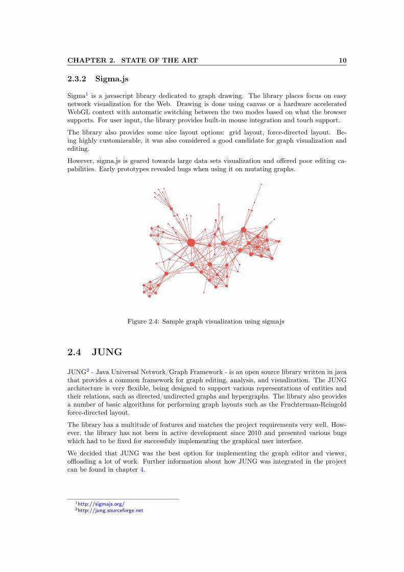
www.eclipse.org/mylyn/images/zest_screen2.jpg . . . . . . . . . . . . . . . . . . . 82.3 Sample visualization of a graph using arborjs . . . . . . . . . . . . . . . . . . . . 92.4 Sample graph visualization using sigmajs . . . . . . . . . . . . . . . . . . . . . . 10
3.1 Visualization of a context graph and a matching pattern . . . . . . . . . . . . . 143.2 Visualization of a context graph and a matching pattern . . . . . . . . . . . . . 15
4.1 Graph edit architecture . . . . . . . . . . . . . . . . . . . . . . . . . . . . . . . . 18
5.1 Android prototype displaying a context graph . . . . . . . . . . . . . . . . . . . 21
6.1 The knowledge of the AmI system about Bob . . . . . . . . . . . . . . . . . . . . 226.2 A pattern for notifying the user to return the book borrowed from Alice . . . . . 236.3 A pattern for triggering suggestions about the means of transportation . . . . . 236.4 A pattern for notifications about possible friends in Bucharest . . . . . . . . . . 246.5 A pattern for notifications about local interesting places . . . . . . . . . . . . . . 246.6 A pattern for notifying the user to return the book borrowed from Alice using
partial matches . . . . . . . . . . . . . . . . . . . . . . . . . . . . . . . . . . . . 25
v
List of Tables
3.1 Available commands for graph editing . . . . . . . . . . . . . . . . . . . . . . . . 13
vi
Notations and Abbreviations
AmI – Ambient IntelligenceGUI – Graphical User InterfaceJUNG – Java Universal Network/Graph FrameworkMVC – Model View ControllerSWT – Standard Widget ToolkitURI – Uniform Resource Identifier
vii
Chapter 1
Introduction
Recent advancements in the field of Ambient Intelligence [5] have brought context-awareness as acentral research topic. Context-awareness refers to the property of a device or computer systemof gathering and using contextual information about its user. The most common example ofsuch information is the GPS location of a mobile phone user. Other examples may include timeof day, neighbouring devices or user activity. However, for more complex ambient intelligentsystems to be developed, more contextual information is required and new aspects of a user’scontext must be explored [6]. To achieve this, more powerful models for representing usercontext are needed.
One such model is based on the idea of representing the context of a user as a graph [6]. Thegraph describes the associations for a set of concepts that describe the individual’s currentstate. Next, specific situations can be identified by matching the context graph to a pattern.A pattern is a context graph which contains generic components that extend the number ofsituations that corespond to a given pattern. Using context graphs, matching context becomesa problem of comparing two graphs.
Olaru et al. [3] propose an algorithm for efficiently matching context graphs with patterns.Although the topic has been extensively studied and proved to be a viable solution for con-text matching, there is currently a lack of tools and applications that use context graphs andshowcase this approach.
This project was developed as a step towards a more practical use of context graphs in the formof a user friendly desktop application which can be used to test the behaviour of context-awareapplications under different circumstances. The final result is a java program that allows theuser to create and edit context graphs and patterns, while observing how the patterns match tothe current context. For the purpose of assisting users in their daily activties, the applicationcan be considered a proof-of-concept as it can only simulate this behaviour.
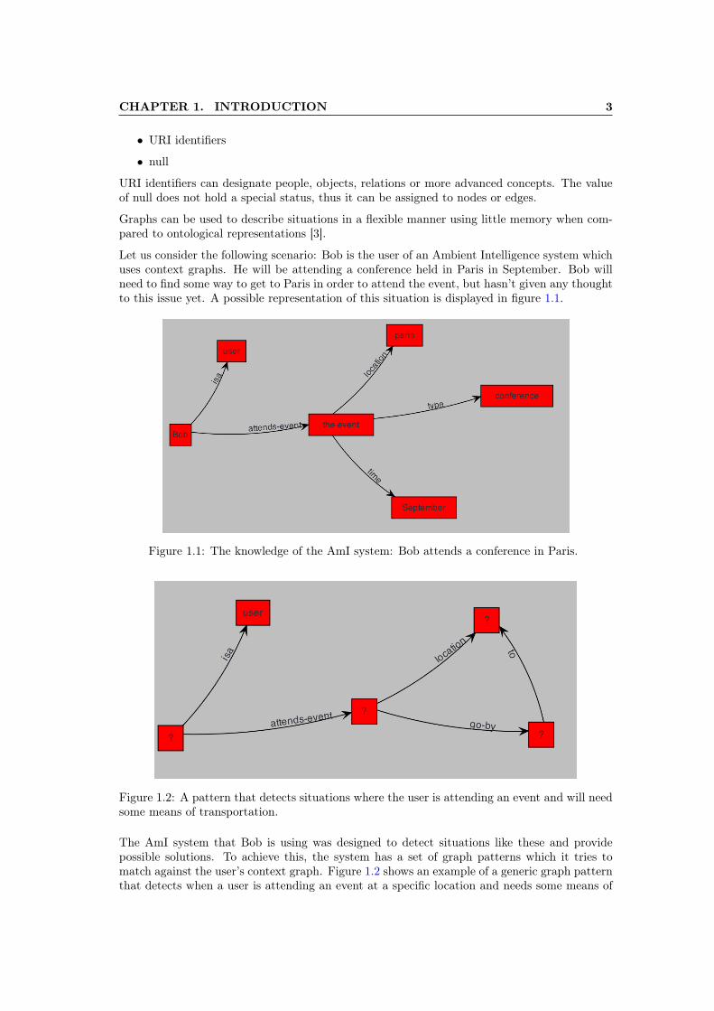
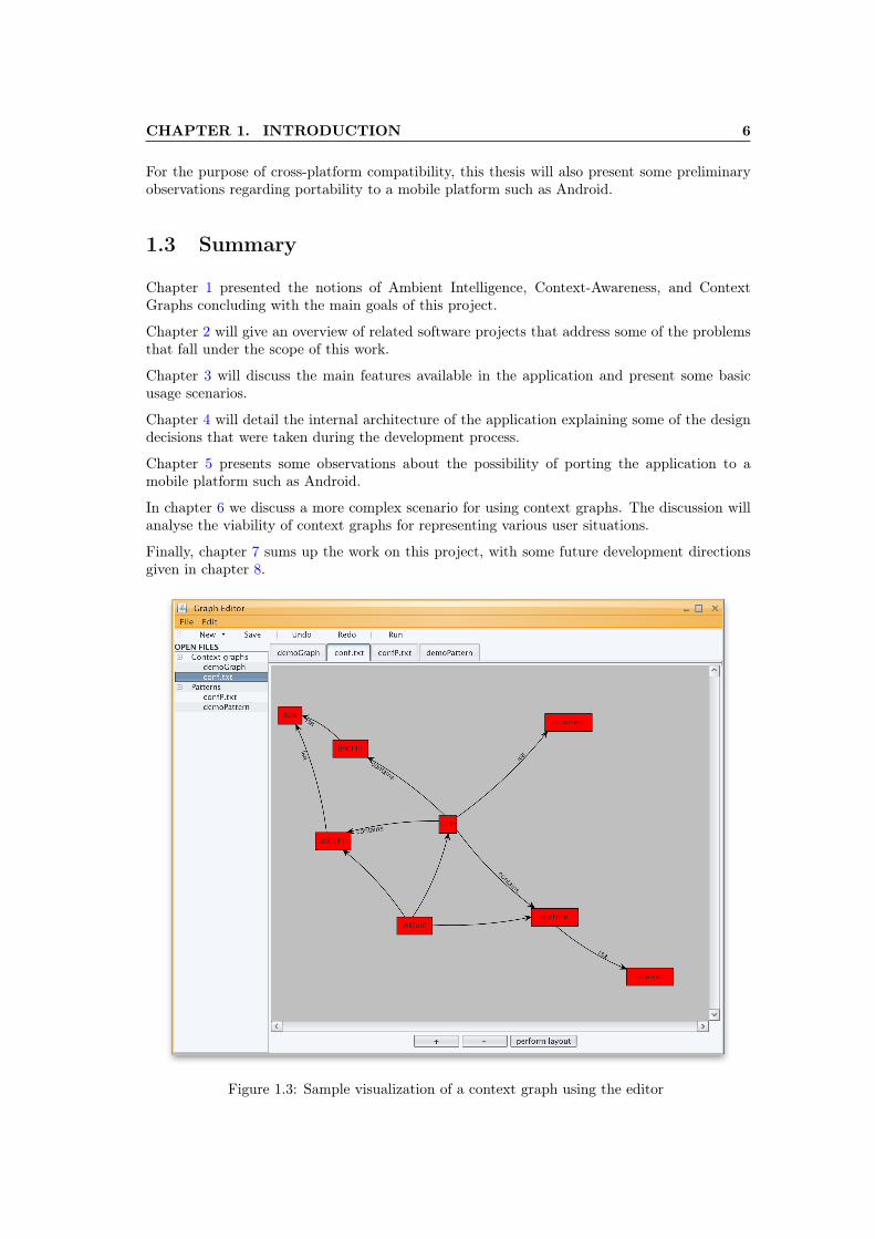
Figure 1.3 shows a simple visualization of a context graph using this application.
In the following sections we provide some background on the topics of Ambient Intelligence,Context-Awareness and Context Graphs before going through a more detailed list of goals forthis project.
1
CHAPTER 1. INTRODUCTION 2
1.1 Background
1.1.1 Ambient Intelligence
The concept of Ambient Intelligence - commonly abbreviated as AmI - is a vision of a futurewhere people will be surrounded by intelligent devices embedded in all kinds of common useobjects that are able to observe and respond to the presence of different individuals. Thesedevices have the purpose to assist the users whenever possible acting in an unobtrusive andoften invisible manner. AmI systems can vary from simple house assistants that improve an in-dividual’s productivity to complex social platforms focused on connecting people with commoninterests [2].
One of the basic requirement for ambient intelligent systems is to have an unobtrusive, but- at the same time - proactive behaviour. This is usually hard to achieve and needs carefulbalancing. Prompting the user too often might result in an overall unpleasent experience [4].A successful proactive AmI system requires context-awareness.
1.1.2 Context-Awareness
Context-awareness [4] is a paradigm in which applications can discover and take advantage ofcontextual information. Although, the notion of context can entail very subtle and high-levelinterpretation of the situation, some studies argued that the only important aspects of contextare: location, the user’s neighbours and resources near the user [8]. Ryan, Pascoe and Morse’s[7] interpretation of the notion is that context represents: location, environment, identity andthe current time. Dey [1] further expands the definition to: "Any information that can beused to characterize the situation of entities (i. e. whether a person, place or object) that areconsidered relevant to the interaction between a user and an application, including the user andthe application themselves".
For successfully developing a context-aware system, a model is required for defining and storingcontext in a structured format. Some of the current studied approaches have been summarizedby Strang and Linnhoff-Popien [10]. Among the models highlighted in the paper are mark-upmodels and graphical models. Mark-up models use mark-up tags and attributes to create profileschemes, while graphical models are based on unified modelling languages [9].
1.1.3 Context graphs
Olaru et al. [6] propose a graph approach for the problem of defining and storing contextualinformation. This section will summarize some of the main concepts and ideas behind thisapproach.
Using graphs for context representation is based on existing knowledge representation methodslike semantic networks, concept maps and conceptual graphs. The graph stores associationsbetween a number of concepts which are relevant for the user’s context. These concepts arepart of a knowledge base used by an AmI system. Formally, a context graph is defined as:
G = (V,E)
V = vi, E = ek, ek = (vi, vj , value)
where vi, vj ∈ V, i, j = 1, n, k = 1,m
The values of vertices and edges can be:
• Strings
CHAPTER 1. INTRODUCTION 3
• URI identifiers
• null
URI identifiers can designate people, objects, relations or more advanced concepts. The valueof null does not hold a special status, thus it can be assigned to nodes or edges.
Graphs can be used to describe situations in a flexible manner using little memory when com-pared to ontological representations [3].
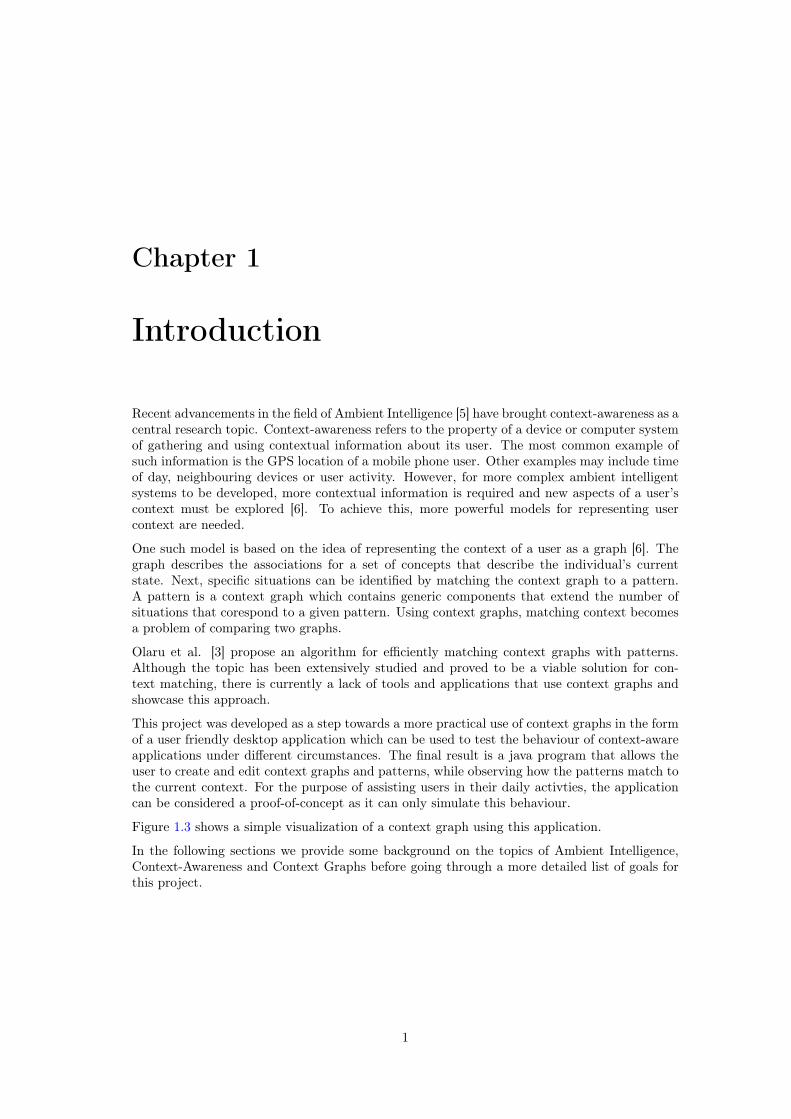
Let us consider the following scenario: Bob is the user of an Ambient Intelligence system whichuses context graphs. He will be attending a conference held in Paris in September. Bob willneed to find some way to get to Paris in order to attend the event, but hasn’t given any thoughtto this issue yet. A possible representation of this situation is displayed in figure 1.1.
Figure 1.1: The knowledge of the AmI system: Bob attends a conference in Paris.
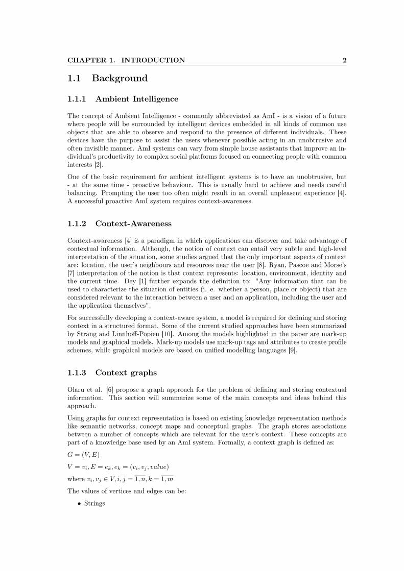
Figure 1.2: A pattern that detects situations where the user is attending an event and will needsome means of transportation.
The AmI system that Bob is using was designed to detect situations like these and providepossible solutions. To achieve this, the system has a set of graph patterns which it tries tomatch against the user’s context graph. Figure 1.2 shows an example of a generic graph patternthat detects when a user is attending an event at a specific location and needs some means of
CHAPTER 1. INTRODUCTION 4
transportation. The pattern should be interpreted as: attending events with locations requirestransportation.
Notice that the pattern uses ? as the value of several nodes. Vertices with this symbol as avalue are considered generic vertices and can be matched to any vertices in the context graph.A pattern is also a graph, but uses special symbols for matching a larger array of situations.Nodes and edges from a a graph pattern can have the following values:
• String
• URI
• The ? symbol
• (only for edges) Regular expression
Edges can have regular expressions that match strings or URIs. For the formal definition ofpatterns, we use the superscript P to denote that a given graph is a pattern or that nodes andedges are part of a pattern.
GP = (V P , EP )
V P = vi, vi = string|URI|?, i = 1, n
EP = ek, ek = (vi, vj , RegularExpression), vi, vj ∈ V P , k = 1,m
As previously mentioned, the AmI system used by Bob will try to match the pattern in figure1.2 against his context graph to determine that Bob will (probably) need a plane ticket toParis. First, we give a simple interpretation for the matching conditions. A pattern P matchescontext graph G if the following conditions are met:
• every vertex from P matches a different vertex from G.
– generic vertices can match any vertex from G.
– non-generic vertices can only match vertices with the same value.
• every edge not containing a regular expression from P matches a different edge from G.
• every edge containing a regular expression from P matches a series of edges from G.
A more formal definition of context graph matching is:
A pattern GPs matches a subgraph G′ of G, with G′ = (V ′, E′) and GP
s = (V PS , EP
S ) , if thereis an injective function f : V P
i − > V ′ so that the following conditions are met:
(1) ∀vPi ∈ V PS , vPi =? or vPi = f(vPi )
(2) ∀eP ∈ EPS , eP = (vPi , v
Pj , value) we have:
if value is a string or an URI, then the edge (f(vPi ), f(vPj ), value) ∈ E′
if value is a regular expression, then it matches the value0, value1, ..., valuep of a series of edgese0, e1, ...ep ∈ E′ where
e0 = (f(vPi ), va0, value0
ek = (vak−1, vak
, value1), k = 1, p− 1
ep = (vap−1 , f(vPj ), valuep)
val∈ v′
An additional condition is that the subgraph G′ should be minimal with respect to the matchingpattern GP . We consider the subgraph minimal if there is no edge in G’ that is not matchingan edge from GP and is not part of a regular expression match with an edge from the pattern.
CHAPTER 1. INTRODUCTION 5
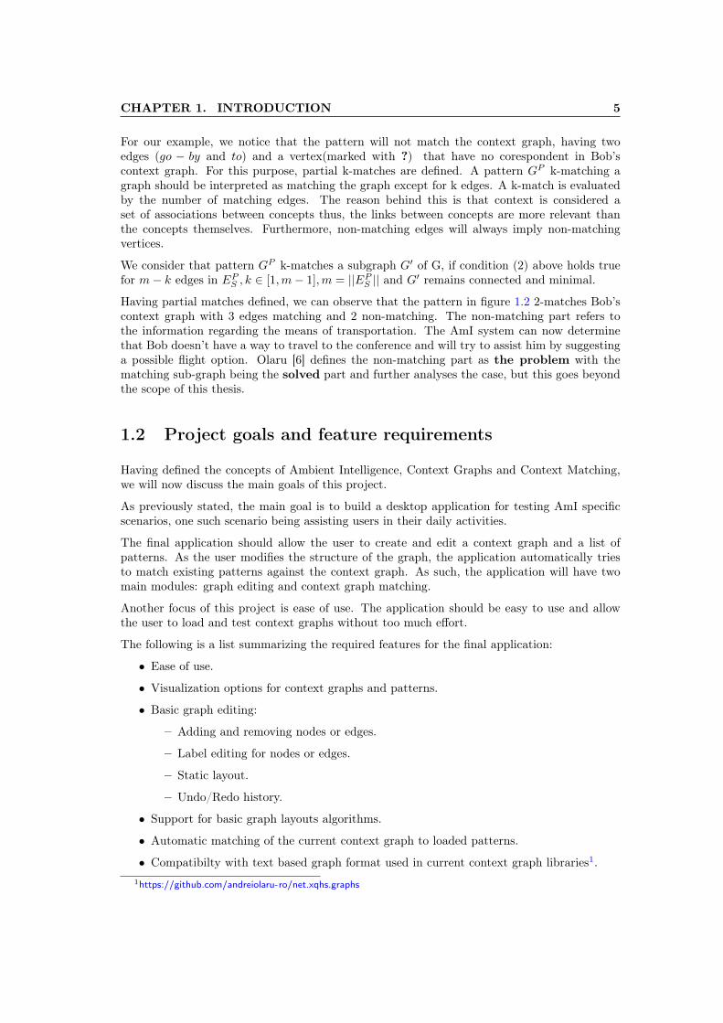
For our example, we notice that the pattern will not match the context graph, having twoedges (go − by and to) and a vertex(marked with ?) that have no corespondent in Bob’scontext graph. For this purpose, partial k-matches are defined. A pattern GP k-matching agraph should be interpreted as matching the graph except for k edges. A k-match is evaluatedby the number of matching edges. The reason behind this is that context is considered aset of associations between concepts thus, the links between concepts are more relevant thanthe concepts themselves. Furthermore, non-matching edges will always imply non-matchingvertices.
We consider that pattern GP k-matches a subgraph G′ of G, if condition (2) above holds truefor m− k edges in EP
S , k ∈ [1,m− 1],m = ||EPS || and G′ remains connected and minimal.
Having partial matches defined, we can observe that the pattern in figure 1.2 2-matches Bob’scontext graph with 3 edges matching and 2 non-matching. The non-matching part refers tothe information regarding the means of transportation. The AmI system can now determinethat Bob doesn’t have a way to travel to the conference and will try to assist him by suggestinga possible flight option. Olaru [6] defines the non-matching part as the problem with thematching sub-graph being the solved part and further analyses the case, but this goes beyondthe scope of this thesis.
1.2 Project goals and feature requirements
Having defined the concepts of Ambient Intelligence, Context Graphs and Context Matching,we will now discuss the main goals of this project.
As previously stated, the main goal is to build a desktop application for testing AmI specificscenarios, one such scenario being assisting users in their daily activities.
The final application should allow the user to create and edit a context graph and a list ofpatterns. As the user modifies the structure of the graph, the application automatically triesto match existing patterns against the context graph. As such, the application will have twomain modules: graph editing and context graph matching.
Another focus of this project is ease of use. The application should be easy to use and allowthe user to load and test context graphs without too much effort.
The following is a list summarizing the required features for the final application:
• Ease of use.
• Visualization options for context graphs and patterns.
• Basic graph editing:
– Adding and removing nodes or edges.
– Label editing for nodes or edges.
– Static layout.
– Undo/Redo history.
• Support for basic graph layouts algorithms.
• Automatic matching of the current context graph to loaded patterns.
• Compatibilty with text based graph format used in current context graph libraries1.1https://github.com/andreiolaru-ro/net.xqhs.graphs
CHAPTER 1. INTRODUCTION 6
For the purpose of cross-platform compatibility, this thesis will also present some preliminaryobservations regarding portability to a mobile platform such as Android.
1.3 Summary
Chapter 1 presented the notions of Ambient Intelligence, Context-Awareness, and ContextGraphs concluding with the main goals of this project.
Chapter 2 will give an overview of related software projects that address some of the problemsthat fall under the scope of this work.
Chapter 3 will discuss the main features available in the application and present some basicusage scenarios.
Chapter 4 will detail the internal architecture of the application explaining some of the designdecisions that were taken during the development process.
Chapter 5 presents some observations about the possibility of porting the application to amobile platform such as Android.
In chapter 6 we discuss a more complex scenario for using context graphs. The discussion willanalyse the viability of context graphs for representing various user situations.
Finally, chapter 7 sums up the work on this project, with some future development directionsgiven in chapter 8.
Figure 1.3: Sample visualization of a context graph using the editor

Chapter 2
State of the art
With Context Graphs being relatively recently introduced, there is currently a limited numberof tools and applications which make use of this approach. This further justifies the need forthis project. Based on the goals presented in section 1.2 we can identify two classes of problemsthat need solving for the development of this project: graph visualization and context graphmatching. The former has been adressed in multiple software projects and there are numerousgraph visualization libraries in open source. For the latter however, there is only one softwareproject oferring support for managing context graphs and running context matching algorithms.In this chapter we will give an overview of this library and present its relation with this project.Next, a series of graph visualisation libraries will be analysed discussing their usefulness for thisproject.
2.1 The net.xqhs.Graphs library
The net.xqhs.Graphs1 is a library written by Andrei Olaru and is designed specifically for usingand testing context graphs. The library provides an easy API for managing context graphs andpatterns. On top of that, it offers the possibility of running graph matching algorithms in thelines of the concepts defined in 1.1.3.
The library also provides some basic graph visualization features, but its support is limited.Figure 2.1 shows a sample visualization using net.xqhs.Graphs. These visualization featureswere designed mostly for debugging and not towards building user interface applications.
The API for doing context matching has two main options:
• QuickMatch.
• Transaction based matching.
QuickMatch determines the matching components between a context graph and a pattern.Transaction based matching is slightly more advanced. It allows doing graph matching betweena pattern and a context graph that is mutating. As the graph changes as a result of a seriesof transactions, the library keeps track of the matches that are still valid and discards the onesthat are not.
It is obvious that net.xqhs.Graphs is very useful for the scope of this project. The developedapplication can be considered an extension to this library, as it provides an easy graph editingenvironment around the context matching platform provided by the library.
1https://github.com/andreiolaru-ro/net.xqhs.graphs
7
CHAPTER 2. STATE OF THE ART 8
Figure 2.1: Visualization of a context graph and a pattern using net.xqhs.graphs
2.2 Zest
Zest: The Eclipse Visualization Toolkit1 is a java library developed in SWT and Draw2D andwas designed to integrate within Eclipse 2.
One of the main features that made Zest a good candidate was the set of graph layout algorithmsit provided:
• Force-directed layout
• Tree Layout
• Radial Layout
The layout module is also packaged separately and can be used independently from the rest ofthe framework.
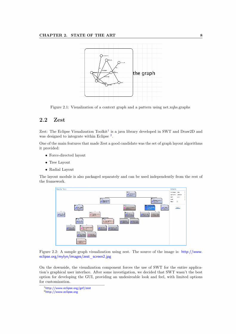
Figure 2.2: A sample graph visualization using zest. The source of the image is: http://www.eclipse.org/mylyn/images/zest_screen2.jpg
On the downside, the visualization component forces the use of SWT for the entire applica-tion’s graphical user interface. After some investigation, we decided that SWT wasn’t the bestoption for developing the GUI, providing an undesireable look and feel, with limited optionsfor customization.
1http://www.eclipse.org/gef/zest2http://www.eclipse.org
CHAPTER 2. STATE OF THE ART 9
2.3 Javascript Frameworks
One of the design directions that was considered towards the beginning of the project waswriting the application as a web-app in javascript. A web-app would have had the advantageof being accessible from a web browser or be packaged in a native wrapper. Apache Cordova1
is good solution for using native wrappers on mobile platforms. The direction was eventuallydiscarded due to a lack of good candidates for graph visualization libraries. The followingsections will discuss the top two choices that were considered.
2.3.1 Arbor.js
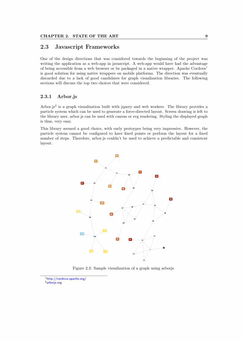
Arbor.js2 is a graph visualization built with jquery and web workers. The library provides aparticle system which can be used to generate a force-directed layout. Screen drawing is left tothe library user, arbor.js can be used with canvas or svg rendering. Styling the displayed graphis thus, very easy.
This library seemed a good choice, with early protoypes being very impressive. However, theparticle system cannot be configured to have fixed points or perform the layout for a fixednumber of steps. Therefore, arbor.js couldn’t be used to achieve a predictable and consistentlayout.
Figure 2.3: Sample visualization of a graph using arborjs
1http://cordova.apache.org/2arborjs.org
CHAPTER 2. STATE OF THE ART 10
2.3.2 Sigma.js
Sigma1 is a javascript library dedicated to graph drawing. The library places focus on easynetwork visualization for the Web. Drawing is done using canvas or a hardware acceleratedWebGL context with automatic switching between the two modes based on what the browsersupports. For user input, the library provides built-in mouse integration and touch support.
The library also provides some nice layout options: grid layout, force-directed layout. Be-ing highly customizeable, it was also considered a good candidate for graph visualization andediting.
However, sigma.js is geared towards large data sets visualization and offered poor editing ca-pabilities. Early prototypes revealed bugs when using it on mutating graphs.
Figure 2.4: Sample graph visualization using sigmajs
2.4 JUNG
JUNG2 - Java Universal Network/Graph Framework - is an open source library written in javathat provides a common framework for graph editing, analysis, and visualization. The JUNGarchitecture is very flexible, being designed to support various representations of entities andtheir relations, such as directed/undirected graphs and hypergraphs. The library also providesa number of basic algorithms for performing graph layouts such as the Fruchterman-Reingoldforce-directed layout.
The library has a multitude of features and matches the project requirements very well. How-ever, the library has not been in active development since 2010 and presented various bugswhich had to be fixed for successfuly implementing the graphical user interface.
We decided that JUNG was the best option for implementing the graph editor and viewer,offloading a lot of work. Further information about how JUNG was integrated in the projectcan be found in chapter 4.
1http://sigmajs.org/2http://jung.sourceforge.net
Chapter 3
Feature overview and usagescenarios
Having the notions of context graph and context matching explained in section 1.1.3, thischapter will present the features available in the final application, leaving implementation detailsfor a later chapter.
We will begin with an overview of the graphical user interface, followed by a discussion of thetwo main feature components: graph editing and graph matching. Next, a series of basic usagescenarios will be presented.
3.1 GUI Overview
As previously mentioned in section 1.2, one of the main focuses when developing the applicationwas usability. The program has features comparable to those of a full fledged graph editor,providing an intuitive set of controls for manipulating the structure of a context graph. Thesecontrols are best described as modal: various commands are issued using a combination ofkeyboard modifiers and mouse clicking.
Graph viewing presents several layout options. The user can choose between: force-directedlayout, circle layout or a custom static layout defined manually.
The editor also has support for saving to disk, with the possibility of loading a set of contextgraphs and patterns directly from file. This is done a through set of menus on the top side, themenus are typical for an editor app behaving in a manner the general user is accustomed to.
Graph editing is done in a standard 2D view positioned in the center of the UI; the view istabbed allowing easy switching between currently opened graphs. Another tree view of allopened files is displayed on the left side.
As the user edits a context graph, the application automatically tries to match it againstexisiting patterns. The threshold for matching is configurable from the menu. The results canbe viewed on the right side of the user interface. On the top-right side a list of all currentlymatching patterns is displayed, while on the bottom-right side a 2D view displays the selectedmatch from this list.
11
CHAPTER 3. FEATURE OVERVIEW AND USAGE SCENARIOS 12
3.2 Graph visualization and editing
One of the initial issues with the visualization of context graphs was using the best possiblelayout. The visual representation should have as few edge overlaps as possible. Next, the overallgraph layout shouldn’t be substantially modified as a result of adding or removing nodes. Andfinally, the same graph should use the same layout everytime it was reloaded.
Trying to compute the best possible layout at each point proved a difficult task and a featurethat wouldn’t be valuable to the overall user experience.
The final solution uses a slightly different approach. Instead of forcing the user to use acertain layout, a static layout was used instead, adding the option of dragging nodes to specificcoordinates. Thus, the user can either modifiy the position of vertices manually or run one ofthe available layout algorithms. This proved a very effective solution, adding no overhead tothe workflow. The available layout algorithms will be detailed next:
• FR layout
• Circle layout
3.2.1 Fruchterman–Reingold force-directed layout
Force-directed algorithms are a class of layout algorithms designed for drawing visually pleasinggraph representations. The main idea is to simulate a particle system with nodes moving freelyand edges acting as springs. The particle system generally uses the following rules:
• Vertices will repel all other vertices to which they are not directly connected.
• Edges act like springs bringing the endpoints together up to a certain threshold.
• All vertices are affected by friction in the 2D space.
• Gravity point. A central position exists which attracts all the vertices in the particlesystem.
Simulation. Initially, all nodes are positioned in the same position. As the physics rules areapplied, the nodes will start moving rapidly until a stable configuration is found. The algorithmruns for a fixed number of steps or until the energy in the system has decreased under a giventhreshold. The complexity is O(n3), but that is not an issue for small to medium sized graphs.
3.2.2 Circle layout
The circle layout is a more simple algorithm. It places all nodes on a circle at evenly distributedpositions. This layout offers a nice visualization for full-mesh graphs.
3.2.3 Editing commands
Even with the two layout algorithms available, in most cases we expect the user to rely onmanually defined static layouts, positioning the vertices with drag gestures. Table 3.1 highlightsthe most common commands available for graph editing.
Actions that actually modify the graph structure or layout will be recorded in a log, giving theuser the option to undo or redo these actions.
CHAPTER 3. FEATURE OVERVIEW AND USAGE SCENARIOS 13
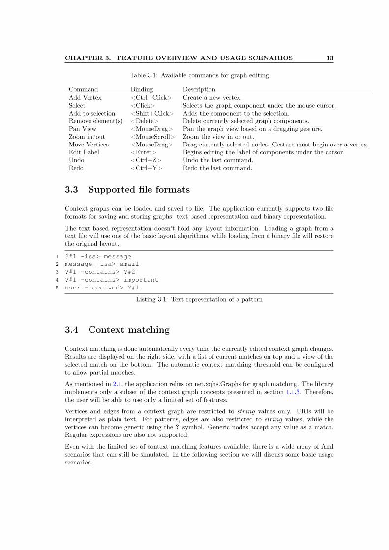
Table 3.1: Available commands for graph editing
Command Binding DescriptionAdd Vertex <Ctrl+Click> Create a new vertex.Select <Click> Selects the graph component under the mouse cursor.Add to selection <Shift+Click> Adds the component to the selection.Remove element(s) <Delete> Delete currently selected graph components.Pan View <MouseDrag> Pan the graph view based on a dragging gesture.Zoom in/out <MouseScroll> Zoom the view in or out.Move Vertices <MouseDrag> Drag currently selected nodes. Gesture must begin over a vertex.Edit Label <Enter> Begins editing the label of components under the cursor.Undo <Ctrl+Z> Undo the last command.Redo <Ctrl+Y> Redo the last command.
3.3 Supported file formats
Context graphs can be loaded and saved to file. The application currently supports two fileformats for saving and storing graphs: text based representation and binary representation.
The text based representation doesn’t hold any layout information. Loading a graph from atext file will use one of the basic layout algorithms, while loading from a binary file will restorethe original layout.
1 ?#1 -isa> message2 message -isa> email3 ?#1 -contains> ?#24 ?#1 -contains> important5 user -received> ?#1
Listing 3.1: Text representation of a pattern
3.4 Context matching
Context matching is done automatically every time the currently edited context graph changes.Results are displayed on the right side, with a list of current matches on top and a view of theselected match on the bottom. The automatic context matching threshold can be configuredto allow partial matches.
As mentioned in 2.1, the application relies on net.xqhs.Graphs for graph matching. The libraryimplements only a subset of the context graph concepts presented in section 1.1.3. Therefore,the user will be able to use only a limited set of features.
Vertices and edges from a context graph are restricted to string values only. URIs will beinterpreted as plain text. For patterns, edges are also restricted to string values, while thevertices can become generic using the ? symbol. Generic nodes accept any value as a match.Regular expressions are also not supported.
Even with the limited set of context matching features available, there is a wide array of AmIscenarios that can still be simulated. In the following section we will discuss some basic usagescenarios.

CHAPTER 3. FEATURE OVERVIEW AND USAGE SCENARIOS 14
3.5 Usage scenarios
At the most basic level, the application can be used as a graph editor, having all the basicfeatures of an editor. The user can load or create a graph, edit it using the controls presentedin 3.2 and save it to disk.
A more advanced usage scenario will be detailed next. As presented in previous chapters, themain purpose of this application is to test the use of context graphs in various scenarios.
We will consider the case of a personal assistant which uses context graphs to track the state ofthe user. The assistant will give suggestions based on a set of previously configured situationsstored as graph patterns. Next, the assistant reacts to changes in context, trying to match it tothe set of patterns. An action will be triggered only as the result of a complete match betweena pattern and the current context graph.
The workflow using the application for this scenario is straightforward. The user would firstcreate or load a context graph representing the information held by the assistant. Next, a set ofpatterns should be created or loaded from files. Finally, the user can edit his graph, simulatinghow his context changes in time and observe the response from the assistant - which comes asthe list of patterns currently matching the context.
Figure 3.1 illustrates a simple scenario: the user is in Bucharest and the month is June; theassistant has been configured to remind him to visit his friend, Robert, when he’s in town. Thecontext graph can be seen in the main view, while the matching pattern is displayed on theright side.
Figure 3.1: Visualization of a context graph and a matching pattern
.
Next, let us assume that the user is hungry and is looking for a place to eat. Figure 3.2 displaysthis change in the context graph. Note the second pattern match displayed on the right panel.
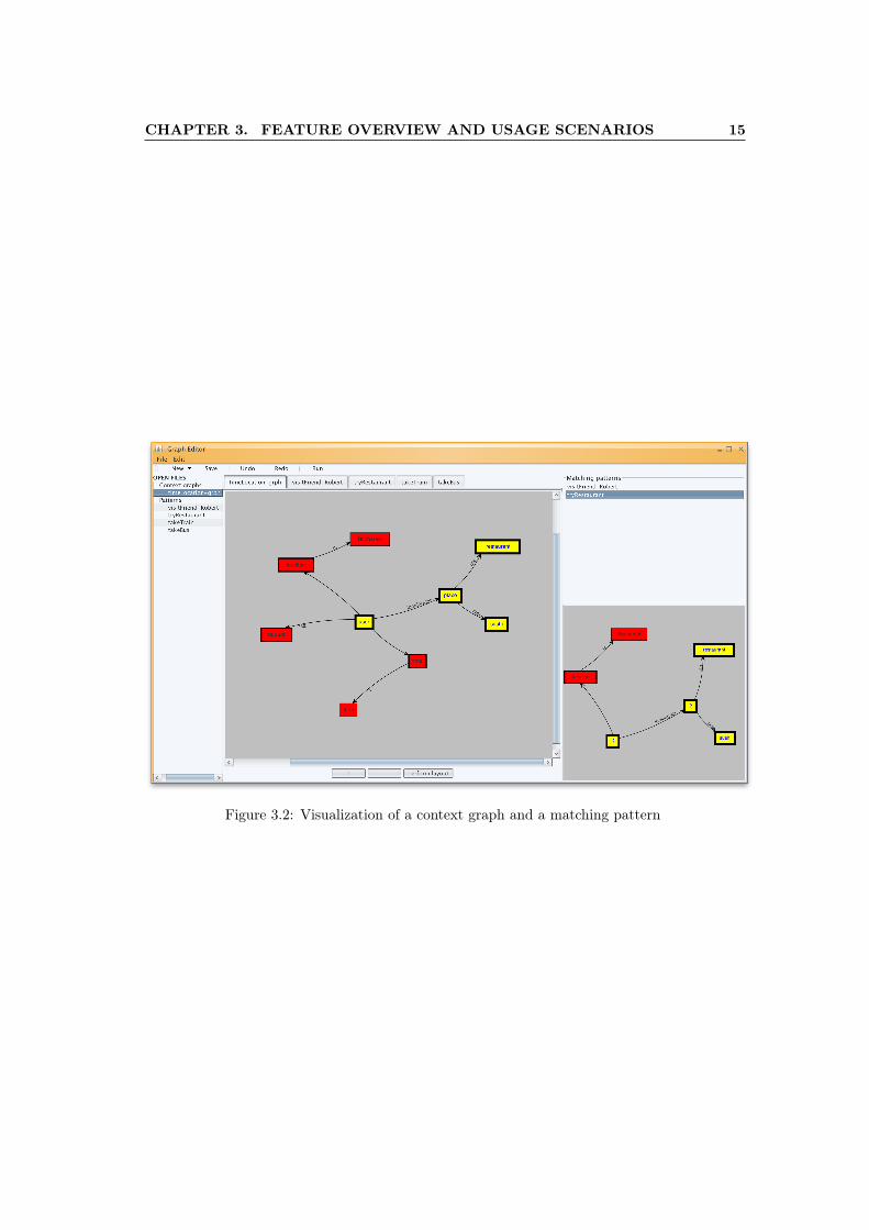
CHAPTER 3. FEATURE OVERVIEW AND USAGE SCENARIOS 15
Figure 3.2: Visualization of a context graph and a matching pattern
Chapter 4
Project implementation
The internal architecture of the graph editor is comprised of several different modules: grapheditor, main controller, context matching workers. This chapter will present the implementationdetails behind these module and explain how they work.
We begin with a discussion regarding some general design decisions which includes the chosencoding language and the external modules used. Next, we will go through each of the maincomponents giving a detailed description of their purpose and how they were implemented.
4.1 Coding language and external modules used
The program developed in this project should be able to run on as many platforms as possible.As mentioned in chapter 2, writing the graph editor as a web-app was one of the initial options.However, because of a lack of graph visualization javascript libraries this idea was eventuallydiscarded. The next language choice providing good cross-platform support was java. Using javahad the advantage of simplifying integration with two useful libraries. Both net.xqhs.Graphsand JUNG are written java and do not provide bindings for other coding languages. Thenet.xqhs.Graphs library is need for running graph matching algorithms while JUNG is neededfor graph editing. Thus, writing the code in java was only natural. The project also includesseveral other third-party libraries: Substance, Trident and JSplitButton. These libraries areused to improve the general look-and-feel of the user interface.
The GUI is written in SWING - one of the core java modules designed for building graphical userinterfaces. Although SWING promotes a model view controller (MVC) architecture, it forcesthe use of its internal event passing system. This causes SWING to be a hard dependency,hindering the ability to port the application to Android. Even so, SWING is still the bestchoice over the other two options: JavaFX is a relatively new framework and is not supportedby JUNG or any other visualization library; SWT has a very old look-and-feel and would havelimited the UI features.
In the end, the project has only a few external dependencies which can be packaged togetheras jar archives. Therefore, the application can be run effortlessly on Windows, Linux and MacOS.
16
CHAPTER 4. PROJECT IMPLEMENTATION 17
4.2 Main Controller
The main controller is the central component of the application. Its purpose is to facilitateinteraction between the other modules by acting as a mediator. At startup, it triggers thecreation of GUI elements. Then, as the GUI controllers are instantiated, they register with themain controller.
The controller will provide abstractions for some of the most common actions performed bythe application. For example, an event from one of the MenuBar items will trigger a call onthe main controller, which in turn will use the appropriate components for fulfilling the userrequest.
4.3 Graph editing
The graph editing component is built on top of the JUNG API. It is generally isolated fromthe rest of the program, having its own set of input handlers. The JUNG framework makesdistinction between the following three elements:
• Graph
• Layout
• Renderer
The Graph class type holds structural information about the graph: a list of vertices connectedthrough edges. JUNG makes heavy use of transformer objects for translating a graph object toa 2D visualization.
The Layout class type is simply a mapping between a vertex and a 2D position. Multiplelayout objects can be chained together, allowing switching to a different layout using a smoothtransition.
The Renderer has two parts: a model and a visualization viewer. The model holds a Graphobject, a Layout object and a list of various transformers. Examples of transformers include:vertex shape transformers, edge transformers, label renderers etc. The visualization viewer isa SWING component which supports drawing to screen.
Listing 4.1 presents an example use of the JUNG API.
1 Graph<Node, Edge> graph = Graphs.<Node,Edge>synchronizedDirectedGraph(new DirectedSparseMultigraph<Node, Edge>());
2 Layout<Node, Edge> layout = new StaticLayout<Node, Edge>(graph);3 VisualizationViewer<Node, Edge> vv = new VisualizationViewer<Node,
Edge>(layout);4 vv.setEventHandler(eventHandler);56 /* The visualization viewer can now be rendered to a JPanel */7 panel.add(vv);
Listing 4.1: Text representation of a pattern
CHAPTER 4. PROJECT IMPLEMENTATION 18
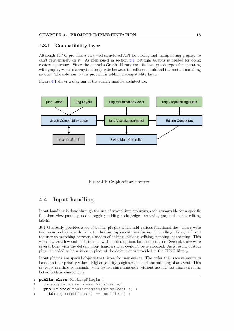
4.3.1 Compatibility layer
Although JUNG provides a very well structured API for storing and manipulating graphs, wecan’t rely entirely on it. As mentioned in section 2.1, net.xqhs.Graphs is needed for doingcontext matching. Since the net.xqhs.Graphs library uses its own graph types for operatingwith graphs, we need a way to interoperate between the editor module and the context matchingmodule. The solution to this problem is adding a compatiblity layer.
Figure 4.1 shows a diagram of the editing module architecture.
net.xqhs.Graph
jung.Graph jung.Layout
Graph Compatibility Layer
jung.VisualizationViewer
jung.VisualizationModel
jung.GraphEditingPlugin
Editing Controllers
Swing Main Controller
Figure 4.1: Graph edit architecture
4.4 Input handling
Input handling is done through the use of several input plugins, each responsible for a specificfunction: view panning, node dragging, adding nodes/edges, removing graph elements, editinglabels.
JUNG already provides a lot of builtin plugins which add various functionalities. There weretwo main problems with using the builtin implementation for input handling. First, it forcedthe user to switching between 4 modes of editing: picking, editing, panning, annotating. Thisworkflow was slow and undesireable, with limited options for customization. Second, there wereseveral bugs with the default input handlers that couldn’t be overlooked. As a result, customplugins needed to be written in place of the default ones provided in the JUNG library.
Input plugins are special objects that listen for user events. The order they receive events isbased on their priority values. Higher priority plugins can cancel the bubbling of an event. Thisprevents multiple commands being issued simultaneously without adding too much couplingbetween these components.
1 public class PickingPlugin {2 /* sample mouse press handling */3 public void mousePressed(MouseEvent e) {4 if(e.getModifiers() == modifiers) {
CHAPTER 4. PROJECT IMPLEMENTATION 19
5 Point2D ip = e.getPoint();6 vertex = pickSupport.getVertex(layout, ip.getX(), ip.getY());7 pickedVertexState.add(vertex);8 }9 }
10 ...11 }
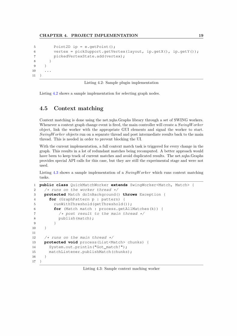
Listing 4.2: Sample plugin implementation
Listing 4.2 shows a sample implementation for selecting graph nodes.
4.5 Context matching
Context matching is done using the net.xqhs.Graphs library through a set of SWING workers.Whenever a context graph change event is fired, the main controller will create a SwingWorkerobject, link the worker with the appropriate GUI elements and signal the worker to start.SwingWorker objects run on a separate thread and post intermediate results back to the mainthread. This is needed in order to prevent blocking the UI.
With the current implementation, a full context match task is triggered for every change in thegraph. This results in a lot of redundant matches being recomputed. A better approach wouldhave been to keep track of current matches and avoid duplicated results. The net.xqhs.Graphsprovides special API calls for this case, but they are still the experimental stage and were notused.
Listing 4.3 shows a sample implementation of a SwingWorker which runs context matchingtasks.
1 public class QuickMatchWorker extends SwingWorker<Match, Match> {2 /* runs on the worker thread */3 protected Match doInBackground() throws Exception {4 for (GraphPattern p : pattern) {5 runWithThreshold(getThreshold());6 for (Match match : process.getAllMatches(k)) {7 /* post result to the main thread */8 publish(match);9 }
10 }1112 /* runs on the main thread */13 protected void process(List<Match> chunks) {14 System.out.println("Got match!");15 matchListener.publishMatch(chunks);16 }17 }
Listing 4.3: Sample context maching worker
Chapter 5
Android portability
During the development of this project, the requirements for porting the application to theAndroid platform were also investigated. This chapter will give some observations on theserequirements.
5.1 Motivation
Context-aware applications usually run on mobile devices. Porting the application to a mobileplatform such as Android would allow the transition towards a real AmI application with thepurpose of providing assistance with daily tasks. An Android app would also benefit from usingthe phone’s sensors, automatically updating the user’s context graph.
5.2 Implementation requirements
A couple implementation details would need to be addressed before porting the application toAndroid. Even though Android uses java as its main app development language, the Dalvikvirtual machine used on smartphones is not compatible to the runtime environment from desk-top systems. The core libraries available on PC are not all supported on mobile. The followingis a highlight of the major additions that would need to be made for a succesful port.
5.2.1 Main controller
First, the Android app will not be able to share the desktop application’s main controller. Thedesktop version uses a non-portable event system (from SWING) and on top of that, the coreapplication logic should be very different on Android. However, individual modules can bereused.
5.2.2 Graph editing
For the purpose of graph editing, JUNG is not compatible with Android. The visualizationcomponent is not supported because it uses SWING for rendering and other desktop-only javamodules. The graph layout component from JUNG is packaged separately and was expected
20
CHAPTER 5. ANDROID PORTABILITY 21
to be compatible with the mobile platform. However, it also failed to run on Android becauseof errors in the virtual machine. Therefore, JUNG is not a viable option on Android.
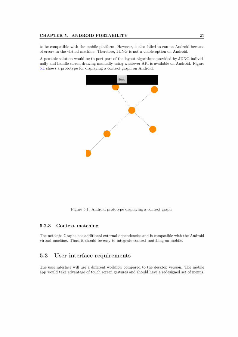
A possible solution would be to port part of the layout algorithms provided by JUNG individ-ually and handle screen drawing manually using whatever API is available on Android. Figure5.1 shows a prototype for displaying a context graph on Android.
Figure 5.1: Android prototype displaying a context graph
5.2.3 Context matching
The net.xqhs.Graphs has additional external dependencies and is compatible with the Androidvirtual machine. Thus, it should be easy to integrate context matching on mobile.
5.3 User interface requirements
The user interface will use a different workflow compared to the desktop version. The mobileapp would take advantage of touch screen gestures and should have a redesigned set of menus.
Chapter 6
Case study and evaluation
Using context graphs for AmI applications presents a wide array of usage especially in the caseof intelligent assistants. In this chapters we will present the advantages as well as disadvantagesin using context graphs for helping users in their daily activities. The discussion will start froma possible scenario and will highlight the strong points in using the approach.
The scenario will consider the case of a user who utilizes the application as a reference for thebehaviour of an AmI assistant for common daily tasks. The assistant will accept notificationsrequests as input, but will also use a set of default, previously-configured patterns when decidingto promopt the user with information.
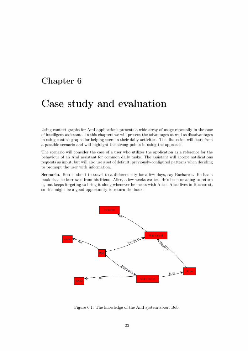
Scenario. Bob is about to travel to a different city for a few days, say Bucharest. He has abook that he borrowed from his friend, Alice, a few weeks earlier. He’s been meaning to returnit, but keeps forgeting to bring it along whenever he meets with Alice. Alice lives in Bucharest,so this might be a good opportunity to return the book.
Figure 6.1: The knowledge of the AmI system about Bob
22
CHAPTER 6. CASE STUDY AND EVALUATION 23
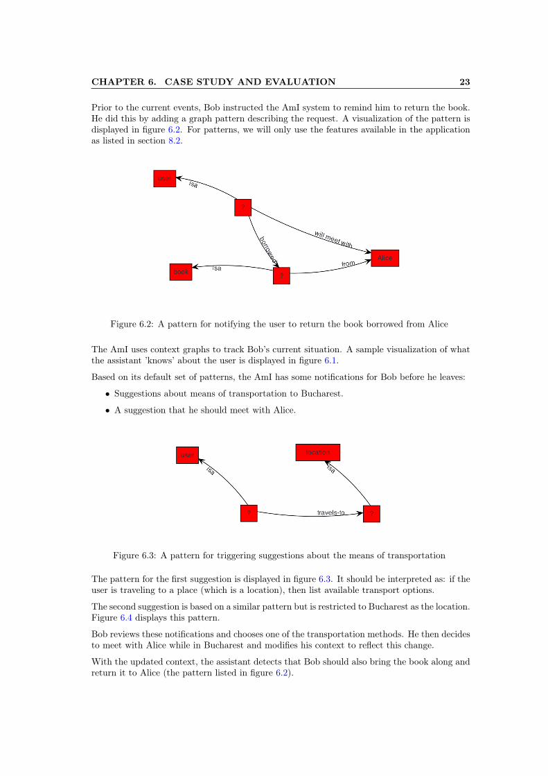
Prior to the current events, Bob instructed the AmI system to remind him to return the book.He did this by adding a graph pattern describing the request. A visualization of the pattern isdisplayed in figure 6.2. For patterns, we will only use the features available in the applicationas listed in section 8.2.
Figure 6.2: A pattern for notifying the user to return the book borrowed from Alice
The AmI uses context graphs to track Bob’s current situation. A sample visualization of whatthe assistant ’knows’ about the user is displayed in figure 6.1.
Based on its default set of patterns, the AmI has some notifications for Bob before he leaves:
• Suggestions about means of transportation to Bucharest.
• A suggestion that he should meet with Alice.
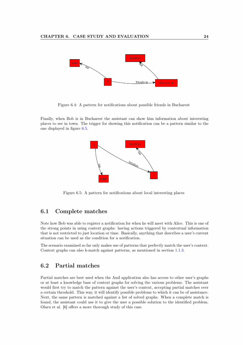
Figure 6.3: A pattern for triggering suggestions about the means of transportation
The pattern for the first suggestion is displayed in figure 6.3. It should be interpreted as: if theuser is traveling to a place (which is a location), then list available transport options.
The second suggestion is based on a similar pattern but is restricted to Bucharest as the location.Figure 6.4 displays this pattern.
Bob reviews these notifications and chooses one of the transportation methods. He then decidesto meet with Alice while in Bucharest and modifies his context to reflect this change.
With the updated context, the assistant detects that Bob should also bring the book along andreturn it to Alice (the pattern listed in figure 6.2).
CHAPTER 6. CASE STUDY AND EVALUATION 24
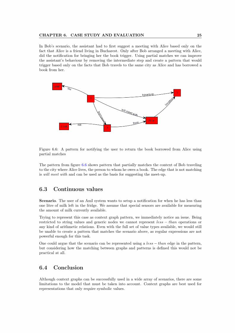
Figure 6.4: A pattern for notifications about possible friends in Bucharest
Finally, when Bob is in Bucharest the assistant can show him information about interestingplaces to see in town. The trigger for showing this notification can be a pattern similar to theone displayed in figure 6.5.
Figure 6.5: A pattern for notifications about local interesting places
6.1 Complete matches
Note how Bob was able to register a notification for when he will meet with Alice. This is one ofthe strong points in using context graphs: having actions triggered by contextual informationthat is not restricted to just location or time. Basically, anything that describes a user’s currentsituation can be used as the condition for a notification.
The scenario examined so far only makes use of patterns that perfectly match the user’s context.Context graphs can also k-match against patterns, as mentioned in section 1.1.3.
6.2 Partial matches
Partial matches are best used when the AmI application also has access to other user’s graphsor at least a knowledge base of context graphs for solving the various problems. The assistantwould first try to match the pattern against the user’s context, accepting partial matches overa certain threshold. This way, it will identify possible problems to which it can be of assistance.Next, the same pattern is matched against a list of solved graphs. When a complete match isfound, the assistant could use it to give the user a possible solution to the identified problem.Olaru et al. [6] offers a more thorough study of this case.
CHAPTER 6. CASE STUDY AND EVALUATION 25
In Bob’s scenario, the assistant had to first suggest a meeting with Alice based only on thefact that Alice is a friend living in Bucharest. Only after Bob arranged a meeting with Alice,did the notification for bringing her the book trigger. Using partial matches we can improvethe assistant’s behaviour by removing the intermediate step and create a pattern that wouldtrigger based only on the facts that Bob travels to the same city as Alice and has borrowed abook from her.
Figure 6.6: A pattern for notifying the user to return the book borrowed from Alice usingpartial matches
The pattern from figure 6.6 shows pattern that partially matches the context of Bob travelingto the city where Alice lives, the person to whom he owes a book. The edge that is not matchingis will meet with and can be used as the basis for suggesting the meet-up.
6.3 Continuous values
Scenario. The user of an AmI system wants to setup a notification for when he has less thanone litre of milk left in the fridge. We assume that special sensors are available for measuringthe amount of milk currently available.
Trying to represent this case as context graph pattern, we immediately notice an issue. Beingrestricted to string values and generic nodes we cannot represent less − than operations orany kind of arithmetic relations. Even with the full set of value types available, we would stillbe unable to create a pattern that matches the scenario above, as regular expressions are notpowerful enough for this task.
One could argue that the scenario can be represented using a less− than edge in the pattern,but considering how the matching between graphs and patterns is defined this would not bepractical at all.
6.4 Conclusion
Although context graphs can be successfully used in a wide array of scenarios, there are somelimitations to the model that must be taken into account. Context graphs are best used forrepresentations that only require symbolic values.
Chapter 7
Conclusion
7.1 Result
The result of this work resulted in a desktop application for testing context graphs underdifferent scenarios, with the main scenario being helping users in their daily activities. Availablefeatures include graph editing and running context matching tasks.
The project described the implementation details of this application, identified and analysedrelevant scenarios where AmI agent would benefit from using context graphs and offered somegeneral directions for a future port to a mobile platform.
The goals of the project have been achieved. The sources are available on github 1.
7.2 Final appreciations
In the end, I found the project to be both interesting and challenging. It was a great opportunityto learn about Context Graphs, a topic which in my opinion has a lot of potential for improvingthe way AmI agents are being designed and developed.
1https://github.com/andreiolaru-ro/AmIciTy-Grph
26
Chapter 8
Future work
With the development process complete and the first version of the application done, we willnow discuss some ideas for future work.
8.1 User interface improvements
The user interface has a lot of areas that can be improved. First, the editor could be overhauledto include a toolbar with the most common types of nodes or edges. Next, a view providinggeneral graph structure information might be added. Another important feature would besupporting user profiles, which would allow easy switching between different configurations. Alist of other miscellaneous improvements might include:
• Copy/Paste support.
• A status bar with information about the current available commands.
• Split-view for graph editing.
• More customization options.
• Better file management.
8.2 Context matching improvements
On the part of context matching, there are several key features that can be further devel-oped. The first would be adding support for more types of generic graph components. Theimprovement would have to be done upstream, in net.xqhs.Graphs. Next, adding more optionsfor fine-tuning the matching algorithm would be a great benefit - allowing the simulation ofeven more scenarios. Finally, some performance improvements might be achieved by using thetransaction based matching algorithm from net.xqhs.Graphs which is optimised for constantlymutating context graphs.
27
CHAPTER 8. FUTURE WORK 28
8.3 Automatic generation of context graph based on userinput
An interesting feature that can be added is building context graphs automatically. The idea isto feed the application information about the user which include: location, time-of-day, weekschedule and so on. The application will then use this information to build a context graph.
A similar approach could be investigated for graph patterns, instead of manually building graphpatterns, the application could provide a more intelligent input interface.
8.4 Mobile platform
Context graph applications are best suited for the mobile environment. With the analysis ofAndroid portability from chapter 5, one of the most sought after feature would be running theapplication on a smart phone.

Bibliography
[1] Anind K Dey. Understanding and using context. Personal and ubiquitous computing,5(1):4–7, 2001.
[2] K. Ducatel, M. Bogdanowicz, F. Scapolo, J. Leijten, and J.C. Burgelman. Scenarios for am-bient intelligence in 2010. Technical report, Office for Official Publications of the EuropeanCommunities, February 2001.
[3] Andrei Olaru. Context matching for ambient intelligence applications. In Nikolaj Björner,Viorel Negru, Tetsuo Ida, Tudor Jebelean, Dana Petcu, Stephen Watt, and Daniela Za-harie, editors, Proceedings of SYNASC 2013, 15th International Symposium on Symbolicand Numeric Algorithms for Scientific Computing, September 23-26, Timisoara, Romania,pages 265–272. IEEE CPS, 2013.
[4] Andrei Olaru, Adina Magda Florea, and Amal El Fallah Seghrouchni. Graphs and pat-terns for context-awareness. In Paulo Novais, Davy Preuveneers, and Juan Corchado,editors, Ambient Intelligence - Software and Applications, 2nd International Symposiumon Ambient Intelligence (ISAmI 2011), University of Salamanca (Spain) 6-8th April, 2011,volume 92 of Advances in Intelligent and Soft Computing, pages 165–172. Springer Berlin/ Heidelberg, 2011.
[5] Andrei Olaru, Adina Magda Florea, and Amal El Fallah Seghrouchni. A context-awaremulti-agent system as a middleware for ambient intelligence. Mobile Networks and Appli-cations, 18(3):429–443, June 2013.
[6] Andrei Olaru, Adina Magda Florea, et al. A graph-based approach to context matching.Scalable Computing: Practice and Experience, 11(4):393–399, 2010.
[7] Nick S Ryan, Jason Pascoe, and David R Morse. Enhanced reality fieldwork: the context-aware archaeological assistant. In Computer applications in archaeology. Tempus Repara-tum, 1998.
[8] Bill Schilit, Norman Adams, and Roy Want. Context-aware computing applications. InMobile Computing Systems and Applications, 1994. WMCSA 1994. First Workshop on,pages 85–90. IEEE, 1994.
[9] Quan Z Sheng and Boualem Benatallah. Contextuml: a uml-based modeling language formodel-driven development of context-aware web services. In Mobile Business, 2005. ICMB2005. International Conference on, pages 206–212. IEEE, 2005.
[10] Thomas Strang and Claudia Linnhoff-Popien. A context modeling survey. In WorkshopProceedings, 2004.
29