energy minimization tool for generating composite … · energy minimization tool for generating...
TRANSCRIPT
U.P.B. Sci. Bull., Series C, Vol. 74, Iss. 4, 2012 ISSN 1454-234x
ENERGY MINIMIZATION TOOL FOR GENERATING COMPOSITE FACIAL EXPRESSIONS IN 3D FACIAL
ANIMATIONS
Mihai Daniel ILIE1, Cristian NEGRESCU2, Dumitru STANOMIR3
În această lucrare, prezentăm un nou instrument de animaţie facială 3D ce poate genera noi expresii faciale compozite, bazându-se pe un set de expresii deja existente. Ideea principală este de a selecta diverse parţi ale obiectului iniţial şi de a le morfa pe fiecare după altă expresie facială ţintă disponibilă, obţinând noi expresii faciale fireşti şi credibile. Algoritmul propus determină automat cât şi cum ar trebui extinsă selecţia în jurul fiecărei părţi a frontierei selecţiei, în funcţie de nivelul de disimilaritate al celor două obiecte în acea zonă. Contribuţia majoră a algoritmului nostu este aceea că determină automat aspectul final al selecţiei, spre deosebire de alte abordări care necesită ca utilizatorul să determine manual, vertex cu vertex, exact cum va arăta selecţia finală. Algoritmul nostru tratează problema în sensul minimizării energiei consumate, folosind noţiunea de distanţă Hausdorff.
In this paper, we present a powerful novel 3D animation tool for generating
composite 3D facial expressions, using a set of already existing ones. The main idea is to select several patches of the face mesh and then morph each one of them towards a different facial expression target model, thus obtaining a new lifelike facial expression with mostly no human interaction. Our algorithm automatically determines how the selection should be expanded around each part of the selection border, and with what span and falloff, depending on the level of dissimilarity which the two models reach at that specific area. The major improvement of our algorithm is that it treats this matter automatically, while other approaches require the user to manually define the final shape of the selection. Our algorithm proposes an energy minimization approach, using the concept of Hausdorff distance.
Keywords: 3D facial animation, 3D facial expressions, 3D morphing, Blend
Shapes, Hausdorff distance
1. Introduction
Facial animation is one of the most challenging tasks undertaken in the field of 3D graphics animation because of the almost infinite variety of gestures 1 PhD student, Department of Telecommunications, University POLITEHNICA of Bucharest,
Romania, e-mail: [email protected] 2 Prof., Department of Telecommunications, University POLITEHNICA of Bucharest, Romania,
e-mail: [email protected] 3 Prof., Department of Telecommunications, University POLITEHNICA of Bucharest, Romania,
e-mail: [email protected]
112 Mihai Daniel Ilie, Cristian Negrescu, Dumitru Stanomir
and emotional states that could be conveyed through the facial movements of an actor, and also because unnatural facial activity could be very easily detected by any human observer [1]. The human face is perhaps the most complex tool of communication. Researchers have invested much interest in the field of facial motion for the past 25 years, trying to implement systems to virtually simulate realistic and convincing facial animations. The field of facial animation has been increasingly important in many areas, such as cinematography, game industry, medical virtual simulations, psychology, linguistics virtual simulations and so on.
In computer graphics, 3D human faces could be animated using one of the two major geometric methods existing so far: the blend-shape animation method and the virtual skeletal/muscle system one.
The latter one proposes implementing virtual muscle and skeletal systems that could properly simulate facial movements by controlling areas on the face surface [2, 3]. The blend shape animation method, also known as morph target animation or shape interpolation, requires a base 3D head model and a specific set of different variations of the same head object, representing various facial expressions. This is the most popular way of animating faces, since it is quite straightforward and easy to accomplish. The proper way for the animator to do this is to create duplicates of the base head model and then manually deform them till various facial expressions are obtained. These new instances of the original head are called blend shape targets. Hence, all blend shape targets share the same geometry and the same connectivity, which means an isomorphic correspondence between the vertices on the base model and those on any of the targets is already established. The correspondence problem being taken care of, another cardinal problem in blend shape animation that needs attention is the interpolation one, i.e. the path vertices should follow from their initial position to the target one. The most commonly used method used in order to achieve this is linear interpolation, due to its very pleasing computational costs [4]. Therefore, realistic and complex facial animations could be performed by morphing the base 3D head model between various blend shape targets, the face gradually changing from one facial expression to another and leaving the impression of the character actually being alive. There are advantages to using morph target animation over skeletal animation, because the modeler can individually create realistic facial movements over which he has absolute control, whereas in the other case he could be constrained by the limitations of the bone system, which could never model perfect and totally natural facial movements [3].
The different blend shape targets are modeled by the animator by using the wide variety of modeling and animation tools available in the common 3D animation software packages. This paper presents a novel powerful 3D animation tool that could save up loads of the animator’s time by automatically generating new vivid and lifelike composite facial expression targets, using a set of already
Energy minimization tool for generating composite facial expressions in 3D facial animations 113
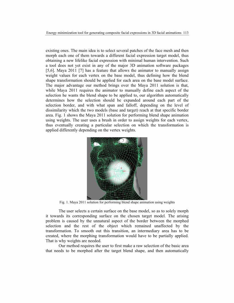
existing ones. The main idea is to select several patches of the face mesh and then morph each one of them towards a different facial expression target model, thus obtaining a new lifelike facial expression with minimal human intervention. Such a tool does not yet exist in any of the major 3D animation software packages [5,6]. Maya 2011 [7] has a feature that allows the animator to manually assign weight values for each vertex on the base model, thus defining how the blend shape transformation should be applied for each area on the base model surface. The major advantage our method brings over the Maya 2011 solution is that, while Maya 2011 requires the animator to manually define each aspect of the selection he wants the blend shape to be applied to, our algorithm automatically determines how the selection should be expanded around each part of the selection border, and with what span and falloff, depending on the level of dissimilarity which the two models (base and target) reach at that specific border area. Fig. 1 shows the Maya 2011 solution for performing blend shape animation using weights. The user uses a brush in order to assign weights for each vertex, thus eventually creating a particular selection on which the transformation is applied differently depending on the vertex weights.
Fig. 1. Maya 2011 solution for performing blend shape animation using weights
The user selects a certain surface on the base model, so as to solely morph it towards its corresponding surface on the chosen target model. The arising problem is caused by the unnatural aspect of the border between the morphed selection and the rest of the object which remained unaffected by the transformation. To smooth out this transition, an intermediary area has to be created, where the morphing transformation would have to be partially applied. That is why weights are needed.
Our method requires the user to first make a raw selection of the basic area that needs to be morphed after the target blend shape, and then automatically
114 Mihai Daniel Ilie, Cristian Negrescu, Dumitru Stanomir
expands the selection area around its border assigning weights for the surrounding vertices, in order for the resulting model to look natural and with no irregularities. The transition area will grow larger only in those areas where the base model is most dissimilar to the target one. In some parts, the selection could even not be extended at all, if there is no need for this. Preliminary tests for this method have been presented in [8]. The implementation was done in C++ using the QT IDE and the common OpenGL libraries.
2. Preliminaries
Our method addresses an energy minimization approach in order to automatically assign weights to the vertices surrounding the selection. In this paper, the energy consumed by a vertex on the mesh is regarded as the Euclidean distance in 3D space that the vertex travels from its initial to its final position. Therefore, the energy consumed for the transport of the iv vertex is denoted as
ivE and has the following expression:
2'2'2' )()()()(iiiiiii vvvvvviiv zzyyxxwwE −+−+−⋅= , (1)
where (
ivx ,ivy ,
ivz ) represents the initial 3D coordinates of the iv
vertex and ( ivx ' , ivy ' , ivz ' ) represents the target 3D coordinates of the same vertex. Considering the morphing transformation is applied on each iv vertex depending on its proper iw weight value, the energy consumed by the iv vertex could be defined as a function of iw .
Consequently, the total amount of travel energy consumed by the vertices surrounding the mesh selection in order for the resulting model to look natural and with no glitches could be expressed as:
∑=
=ΜΜT
i
N
iivtinT wESE
1)(),,( , (2)
where TN is the total number of affected vertices exterior to the selection
and ∈iw (0,1) . For the vertices belonging to the selection or to the selection border, the weight equals 1, whereas the unaffected vertices have 0 weights.
inΜ and tΜ represent the two domain mesh vector fields that define the initial and target meshes in discrete form, while S is the selection. inΜ and tΜ have the
Energy minimization tool for generating composite facial expressions in 3D facial animations 115
same number of elements (vertices) and their elements correspond isomorphically. Relative to these three parameters, our algorithm automatically assigns weight values to the vertices on inΜ which surround the S selection.
Therefore, the weights have to be assigned in such a way, so that the resulting model should look natural (with no glitches) and also the totally consumed energy should be kept at a minimum (so as not to needlessly affect some mesh parts). For this purpose, we use the concept of Hausdorff distance, which is a very frequently used technique for measuring surface errors [9], shape matching and also image recognition [10].
Let 1δ and 2δ be two continuous 3D surfaces. Considering 1δv and
2δv are
the vertices which define the 1δ and 2δ discrete surfaces, the Hausdorff distance between 1δ and 2δ is defined as:
⎟⎟⎠
⎞⎜⎜⎝
⎛=
∈∈ 212211
,minmax),( 21 δδδδ δδ
δδ vvHDvv
, (3)
where ⋅⋅, describes the Euclidean norm between two vertices in 3D
space. Since ),(),( 1221 δδδδ HDHD ≠ , the two-sided Hausodrff distance [11] has the following expression:
( )),(),,(max),( 122121 δδδδδδ HDHDHDs = (4)
In the following sections we shall use the concepts presented so far in
order to describe our algorithm. At all events, we find it useful to explain the terms which are to be used henceforth. The border vertices are vertices that are placed on the border of the selection. We say that all vertices that are direct neighbors to such border vertices (and are not included in the selection) belong to the first ring (of neighbor vertices) incident to the selection. If a vertex is a direct neighbor to a vertex that belongs to the previously defined first ring and belongs neither to the selection surface nor to the first ring of neighbors, then it belongs to the second ring of neighbor vertices. In other words, if there is any possible way to link our vertex to a border vertex by moving only through one intermediary vertex, then our vertex belongs to the second ring of neighbor vertices (providing it is not placed on the border itself or on the first ring). The explanation goes the same for the third ring, and so on.
116 Mihai Daniel Ilie, Cristian Negrescu, Dumitru Stanomir
3. Automatically assigning the weight values
Let inB be the set of border vertices corresponding to the initial mesh.
tB shall then be its equivalent on the target mesh. The border vertices are
described as inBiv , and
tBiv , , with ( )inBCardi …1= and )()( tin BCardBCard = .
( )⋅Card defines the number of elements for a finite set. The inBiv , vertex on the
initial mesh corresponds to the tBiv , vertex on the target one. The finite vertex sets
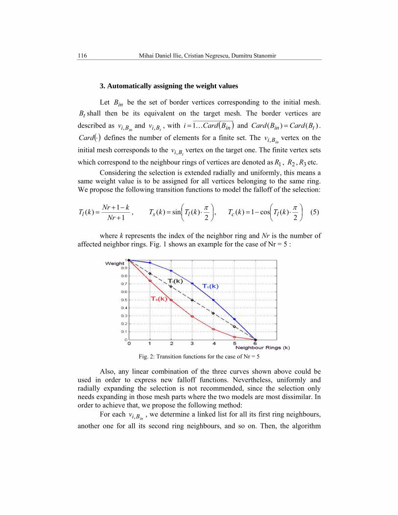
which correspond to the neighbour rings of vertices are denoted as 1R , 2R , 3R etc. Considering the selection is extended radially and uniformly, this means a
same weight value is to be assigned for all vertices belonging to the same ring. We propose the following transition functions to model the falloff of the selection:
11)(+−+
=Nr
kNrkTl , ⎟⎠⎞
⎜⎝⎛ ⋅=
2)(sin)( πkTkT ls , ⎟
⎠⎞
⎜⎝⎛ ⋅−=
2)(cos1)( πkTkT lc (5)
where k represents the index of the neighbor ring and Nr is the number of affected neighbor rings. Fig. 1 shows an example for the case of Nr = 5 :
Fig. 2: Transition functions for the case of Nr = 5
Also, any linear combination of the three curves shown above could be used in order to express new falloff functions. Nevertheless, uniformly and radially expanding the selection is not recommended, since the selection only needs expanding in those mesh parts where the two models are most dissimilar. In order to achieve that, we propose the following method: For each
inBiv , , we determine a linked list for all its first ring neighbours, another one for all its second ring neighbours, and so on. Then, the algorithm
Energy minimization tool for generating composite facial expressions in 3D facial animations 117
decides how much the selection is to be extended around this specific vertex, depending on the energy consumed for its transformation into its equivalent on the target mesh. Therefore:
( )tininBi BiBiv vvE ,, ,1
,= (6)
As a result, for each border vertex, a different Nr value is obtained, depending on the computed norm
tin BiBi vv ,, , . Since the result also varies
depending on the object’s number of triangles, several tests and experiments on different 3D objects in various situations have led us to the following formula for Nr determination:
⎥⎥
⎦
⎤
⎢⎢
⎣
⎡
⋅
+⋅=
−2,,
,10
,1)()(
D
vvvNr tin
in
BiBiBi τσ , (7)
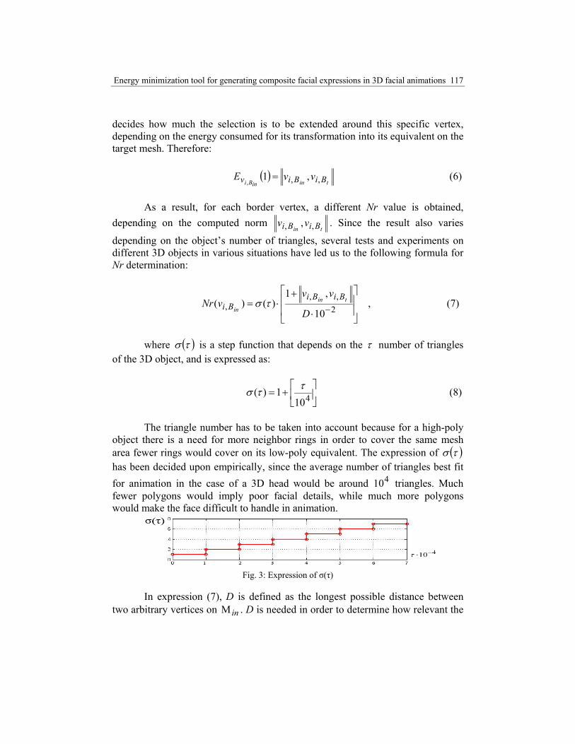
where ( )τσ is a step function that depends on the τ number of triangles of the 3D object, and is expressed as:
⎥⎦
⎤⎢⎣
⎡+= 410
1)( ττσ (8)
The triangle number has to be taken into account because for a high-poly
object there is a need for more neighbor rings in order to cover the same mesh area fewer rings would cover on its low-poly equivalent. The expression of ( )τσ has been decided upon empirically, since the average number of triangles best fit for animation in the case of a 3D head would be around 410 triangles. Much fewer polygons would imply poor facial details, while much more polygons would make the face difficult to handle in animation.
Fig. 3: Expression of σ(τ)
In expression (7), D is defined as the longest possible distance between two arbitrary vertices on inΜ . D is needed in order to determine how relevant the
118 Mihai Daniel Ilie, Cristian Negrescu, Dumitru Stanomir
tin BiBi vv ,, , norms are relative to the object’s geometry. Finally, the result
obtained in (7) is used in one of the transition functions proposed in (5) in order to obtain different falloffs around each border vertex. When the falloffs of two different border vertices are superimposed, several vertices are assigned more than one weight value, and in this case our algorithm chooses the higher weight value.
4. Refining the weights by means of energy minimization
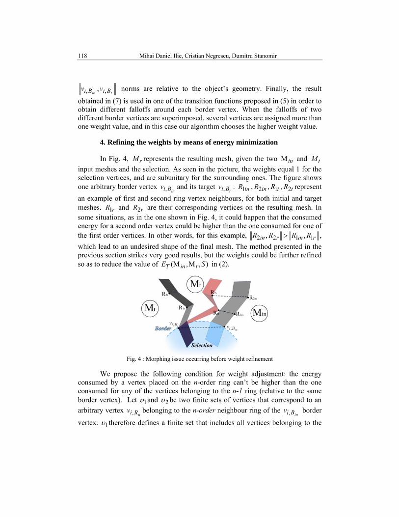
In Fig. 4, rM represents the resulting mesh, given the two inΜ and tM input meshes and the selection. As seen in the picture, the weights equal 1 for the selection vertices, and are subunitary for the surrounding ones. The figure shows one arbitrary border vertex
inBiv , and its target tBiv , . inR1 , inR2 , tR1 , tR2 represent
an example of first and second ring vertex neighbours, for both initial and target meshes. rR1 and rR2 are their corresponding vertices on the resulting mesh. In some situations, as in the one shown in Fig. 4, it could happen that the consumed energy for a second order vertex could be higher than the one consumed for one of the first order vertices. In other words, for this example, rinrin RRRR 1122 ,, > , which lead to an undesired shape of the final mesh. The method presented in the previous section strikes very good results, but the weights could be further refined so as to reduce the value of ),,( SE tinT ΜΜ in (2).
Fig. 4 : Morphing issue occurring before weight refinement
We propose the following condition for weight adjustment: the energy
consumed by a vertex placed on the n-order ring can’t be higher than the one consumed for any of the vertices belonging to the n-1 ring (relative to the same border vertex). Let 1υ and 2υ be two finite sets of vertices that correspond to an arbitrary vertex
nRiv , belonging to the n-order neighbour ring of the inBiv , border
vertex. 1υ therefore defines a finite set that includes all vertices belonging to the
Energy minimization tool for generating composite facial expressions in 3D facial animations 119
(n-1) ring of neighbours relative to inBiv , , while 2υ defines a finite set of the
target vertices which correspond to the initial ones placed in 1υ . Using (1) and (4) and the notations from this paragraph, the condition could be expressed as:
( )≤
nRinRi vv wE,,
( )21,υυsHD (9)
In case the condition is not respected, the weight value must be changed to one that assures the newly computed energy is equal to the Hausdorff distance it was previously compared to. In the example of Fig. 4, and with the notations from this figure, rR2 would have to be replaced in such a way that
rinrin RRRR 1122 ,, = , which would considerably smooth out the aspect of rM .
5. Results and Conclusions
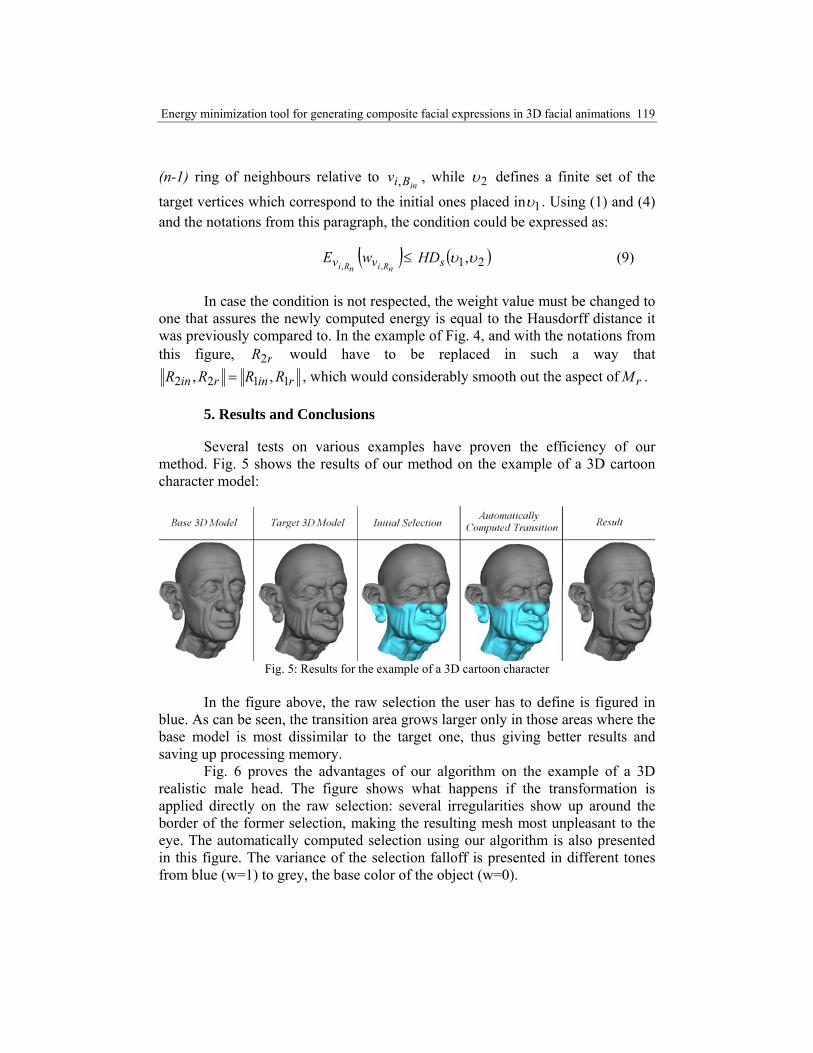
Several tests on various examples have proven the efficiency of our method. Fig. 5 shows the results of our method on the example of a 3D cartoon character model:
Fig. 5: Results for the example of a 3D cartoon character
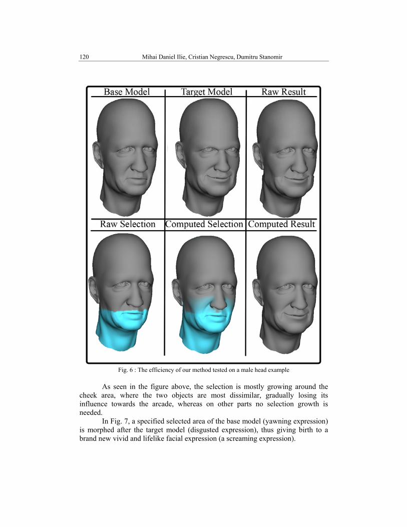
In the figure above, the raw selection the user has to define is figured in blue. As can be seen, the transition area grows larger only in those areas where the base model is most dissimilar to the target one, thus giving better results and saving up processing memory. Fig. 6 proves the advantages of our algorithm on the example of a 3D realistic male head. The figure shows what happens if the transformation is applied directly on the raw selection: several irregularities show up around the border of the former selection, making the resulting mesh most unpleasant to the eye. The automatically computed selection using our algorithm is also presented in this figure. The variance of the selection falloff is presented in different tones from blue (w=1) to grey, the base color of the object (w=0).
120 Mihai Daniel Ilie, Cristian Negrescu, Dumitru Stanomir
Fig. 6 : The efficiency of our method tested on a male head example
As seen in the figure above, the selection is mostly growing around the
cheek area, where the two objects are most dissimilar, gradually losing its influence towards the arcade, whereas on other parts no selection growth is needed.
In Fig. 7, a specified selected area of the base model (yawning expression) is morphed after the target model (disgusted expression), thus giving birth to a brand new vivid and lifelike facial expression (a screaming expression).
Energy minimization tool for generating composite facial expressions in 3D facial animations 121
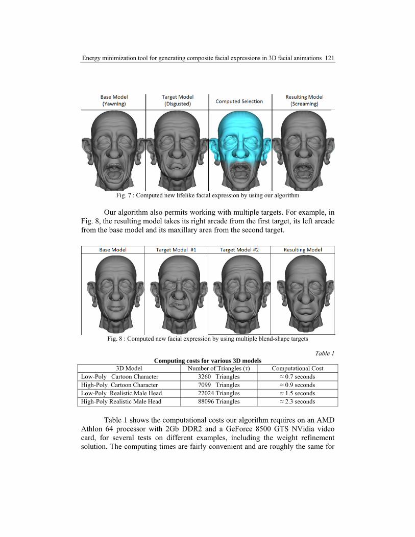
Fig. 7 : Computed new lifelike facial expression by using our algorithm
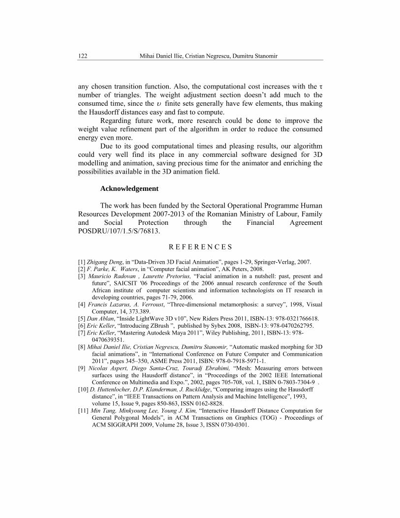
Our algorithm also permits working with multiple targets. For example, in Fig. 8, the resulting model takes its right arcade from the first target, its left arcade from the base model and its maxillary area from the second target.
Fig. 8 : Computed new facial expression by using multiple blend-shape targets
Table 1
Computing costs for various 3D models 3D Model Number of Triangles (τ) Computational Cost
Low-Poly Cartoon Character 3260 Triangles ≈ 0.7 seconds High-Poly Cartoon Character 7099 Triangles ≈ 0.9 seconds Low-Poly Realistic Male Head 22024 Triangles ≈ 1.5 seconds High-Poly Realistic Male Head 88096 Triangles ≈ 2.3 seconds Table 1 shows the computational costs our algorithm requires on an AMD Athlon 64 processor with 2Gb DDR2 and a GeForce 8500 GTS NVidia video card, for several tests on different examples, including the weight refinement solution. The computing times are fairly convenient and are roughly the same for
122 Mihai Daniel Ilie, Cristian Negrescu, Dumitru Stanomir
any chosen transition function. Also, the computational cost increases with the τ number of triangles. The weight adjustment section doesn’t add much to the consumed time, since the υ finite sets generally have few elements, thus making the Hausdorff distances easy and fast to compute. Regarding future work, more research could be done to improve the weight value refinement part of the algorithm in order to reduce the consumed energy even more.
Due to its good computational times and pleasing results, our algorithm could very well find its place in any commercial software designed for 3D modelling and animation, saving precious time for the animator and enriching the possibilities available in the 3D animation field.
Acknowledgement The work has been funded by the Sectoral Operational Programme Human
Resources Development 2007-2013 of the Romanian Ministry of Labour, Family and Social Protection through the Financial Agreement POSDRU/107/1.5/S/76813.
R E F E R E N C E S
[1] Zhigang Deng, in “Data-Driven 3D Facial Animation”, pages 1-29, Springer-Verlag, 2007. [2] F. Parke, K. Waters, in “Computer facial animation”, AK Peters, 2008. [3] Mauricio Radovan , Laurette Pretorius, “Facial animation in a nutshell: past, present and
future”, SAICSIT '06 Proceedings of the 2006 annual research conference of the South African institute of computer scientists and information technologists on IT research in developing countries, pages 71-79, 2006.
[4] Francis Lazarus, A. Verroust, “Three-dimensional metamorphosis: a survey”, 1998, Visual Computer, 14, 373.389.
[5] Dan Ablan, “Inside LightWave 3D v10”, New Riders Press 2011, ISBN-13: 978-0321766618. [6] Eric Keller, “Introducing ZBrush ”, published by Sybex 2008, ISBN-13: 978-0470262795. [7] Eric Keller, “Mastering Autodesk Maya 2011”, Wiley Publishing, 2011, ISBN-13: 978-
0470639351. [8] Mihai Daniel Ilie, Cristian Negrescu, Dumitru Stanomir, “Automatic masked morphing for 3D
facial animations”, in “International Conference on Future Computer and Communication 2011”, pages 345–350, ASME Press 2011, ISBN: 978-0-7918-5971-1.
[9] Nicolas Aspert, Diego Santa-Cruz, Touradj Ebrahimi, “Mesh: Measuring errors between surfaces using the Hausdorff distance”, in “Proceedings of the 2002 IEEE International Conference on Multimedia and Expo.”, 2002, pages 705-708, vol. 1, ISBN 0-7803-7304-9 .
[10] D. Huttenlocher, D.P. Klanderman, J. Rucklidge, “Comparing images using the Hausdorff distance”, in “IEEE Transactions on Pattern Analysis and Machine Intelligence”, 1993, volume 15, Issue 9, pages 850-863, ISSN 0162-8828.
[11] Min Tang, Minkyoung Lee, Young J. Kim, “Interactive Hausdorff Distance Computation for General Polygonal Models”, in ACM Transactions on Graphics (TOG) - Proceedings of ACM SIGGRAPH 2009, Volume 28, Issue 3, ISSN 0730-0301.