contributions to fluid dynamics in jetmills by · pdf filemechanical crushers, shears,...
TRANSCRIPT
U.P.B. Sci. Bull., Series D, Vol. 71, Iss. 4, 2009 ISSN 1454-2358
CONTRIBUTIONS TO FLUID DYNAMICS IN JETMILLS BY A NEW AERODYNAMIC MODEL OF SUPERSONIC FLOW
Ileana FULGA1, Eugen STRĂJESCU2
Se propune un nou model aerodinamic al jetului, pentru studii şi evaluări
ulterioare, considerând complexitatea matematică a mecanicii fluidelor, caracterizată de puţine cazuri care sunt rezolvate prin metode numerice, cu algoritmi deosebiţi şi clustere formate din multe computere. Acest material prezintă o analiză critică a modelului macroscopic al morilor cu jeturi în spirală, menţionând noua disciplină de Calcul al Dinamicii Fluidelor (CFD), şi anticipând avantajele vizive ale analizei fluxului supersonic cu metoda experimentală de măsurare optică a vitezei particulelor (PIV).
A new aerodynamic model of the grinding jet is proposed for further studies
and evaluations, considering the mathematical complexity of fluid mechanics, where quite few cases are being solved by numerical methods, typically with special algorithms and clusters of many computers. This material presents a citical analysis of the macroscopic model of spiral jetmills, mentioning the modern discipline of Computational Fluid Dynamics (CFD), and envisaging advantages of the visual nature of fluid flow by Particle Image Velocimetry (PIV), through experimental method of optical measurement of particles speed..
Keywords: micronization, jetmill, aerodynamic model, CFD, asthma, APIs
1. Introduction
The modern developments of active pharmaceutical ingredients (APIs) for inhalation route of administration in asthma therapies, by micronized aerosols, has shown that, both the particle size of the active and of other excipients are critical to the effectiveness of the final formulated product.
Regulatory agencies : the ministries of health in EU and FDA-USA are requesting that tight control on the size and on the distribution, in agreement with a good understanding of the material itself, is obtained and is reproducible for every API employed for inhalation therapy.
1; Ph.D Student,Validation Manager – APTM SA, Switzerland, e-mail: [email protected] 2 Prof., Depart. of Machines and Production Systems, University “Politehnica” of Bucharest, România, e-mail: [email protected]
192 Ileana Fulga, Eugen Străjescu
The inhalation route has many advantages over other forms of delivery, as it provides a rapid drug uptake in the case of respiratory diseases like asthma, chronic bronchitis and chronic obstructive pulmonary disease (COPD), but also for some systemic deliveries. Particle size dictates which areas of the respiratory tract are required to be targeted in order to have a greatest efficacy for the product.
The final formulated product can take several forms, the most common being the multidose pressurised inhaler (pMDI) and the dry powder inhaler (DPI). Both are very common in the treatment of asthma, although is taking into account considerable research that supports the delivery of other APIs by this route, like antipsychotics, opioids, male fertility actives, caffeine, nicotine, insuline etc.
Micronisation can reproducibly deliver an API within the size range required for the development of inhalation products, from small, trial quantities of new active ingredients, up to large scale manufacture for commercial volumes. Particles are required to be less than 10 microns, usually with a majority of the particles between 2 and 5 microns, in order to be inhaled into the respiratory tract. Particles greater in size than those presented above would impact on the back of the throat where there is no therapeutic benefit, especially when dealing with steroids; in the same time, if there are too many `fines' present in the micronised product, these offer alsolittle therapeutic value, as they are often exhaled with the patient's next breath. The method through the micronised product is tested to confirm the particle size is as critical as the micronisation process itself.
Very few techniques are capable of supplying a powder in the size range discussed; micronisation is one of them and has proven over decades that it is a reliable method. There are essentially two ways for the micronization to be carried out; the method selected is usually driven by the material characteristics, such as particle size/shape, flowability, moisture/solvent content and hardness. This will determine the way for the powder to respond to the chosen milling technique, and what the final outcome of the particle size distribution will be. The two most common designs of mills used for micronisation of powders for inhalation are spiral jet mills and opposed jet mills.
Therefore, the analysis and understanding of grinding process by jetmilling is of utmost importance, being reckoned the superiority of spiral jetmills in terms of easy cleaning and simple operation, allowing quick adjustments to produce varying grades of material, with particular care to imposed working parameters.
Critical overview of the macroscopic model of jetmills Well before booming of pharma industry, fine powders have been
requested by many other applications, in metallurgy followed by chemical industries, that made considerable efforts for the development of countless, mechanical crushers, shears, breakers, ball and pin mills, granulators, pulverizers etc.

Contributions to fluid dynamics in jetmills by a new aerodynamic model of supersonic flow 193
2. Critical overview of the macroscopic model of jetmills
Fig. 1. Evolution of fluid-energy mills: impact, opposed-jets, toroidal and spiral jetmills
It was soon demonstrated that mechanical grinding can offer only particle sizes above 40-50 microns, and for the ultra-fine grinding, below 15 microns, equipment using high speed air flows or superheated steam that evolved during the last century, named "fluid energy mill" or "jetmill" have been developped. Generally, the jetmills are designed to grind solid pulverulent materials to a predetermined size by the action of jets of gaseous fluid introduced at super-atmospheric pressure and high velocities into a confined zone - the grinding chamber.
The spiral jetmill consists of a venturi injector that fluidises and pushes the powder into a flat, cylindrical grinding chamber, where the particles are subjected to a combination of forces, generated by several, peripheric, angled jets, resulting from particle-to-particle collisions, leading to size reduction.
194 Ileana Fulga, Eugen Străjescu
The fundamentals of this process did not received much attention for many years, and these jetmills evoluted silently, based on empiric postulates commented in the light of recent findings, demolishing the mechanical, macroscopic model, replaced by a new aerodinamic model of flow, confimed in practice.
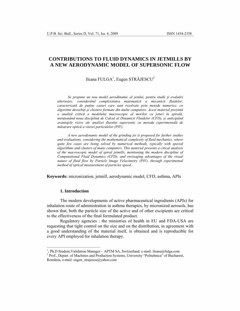
Fig. 2. Empirical theory of the combination of forces. Legend: π - Particle subjected to collision; Δ
- Supersonic air nozzle; α - Normal gradient of supersonic jet; Φ - Drag force; T - Tangential force, inertial; Σ - Resultant force by combination; β - Collision gradient called GRINDING
ANGLE
According to a first postulate, the particles are first injected into the grinding chamber by the feed flow which is generated by a venturi system, and combined then into a high-speed, subsonic, tangential flow, occupying the outer third of chamber. Those particles passing in front of a supersonic jet are pushed by the drag force radially colliding with neighbor particles from the same tangetial flow. The mechanical model shows a combination of forces, reduced by order of magnitude to simple drag/inertial components, explaining the fact that any variation of the grinding angle would determine different resultants - intended as effective, collision force, and that factor may vary the fineness of micronised powder. This theory is false, because the supersonic jet flow at 2.1-2.3 Mach speed has a behaviour as an impenetrable wall for the tangential flow, and no particle is able to arrive in front of the nozzle, and to be acted by the drag force.
Contributions to fluid dynamics in jetmills by a new aerodynamic model of supersonic flow 195
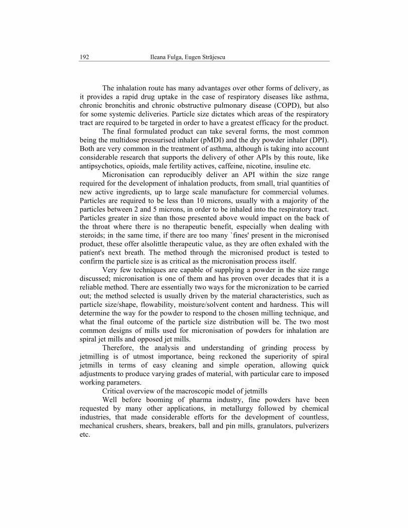
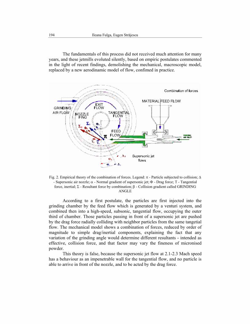
Fig. 3. Theory of circular, tangential flow inside the grinding chamber. Legend: π - Particle subjected to collision; Δ - Supersonic air nozzle; α - Normal gradient of supersonic jet; Φ - Drag
force; T - Tangential force, inertial; Σ - Resultant force by combination; β - Collision gradient called GRINDING ANGLE
¥.
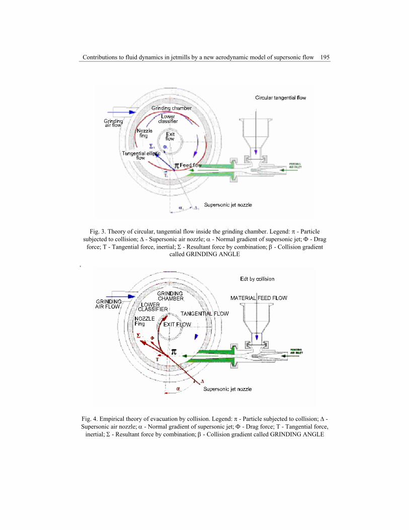
Fig. 4. Empirical theory of evacuation by collision. Legend: π - Particle subjected to collision; Δ - Supersonic air nozzle; α - Normal gradient of supersonic jet; Φ - Drag force; T - Tangential force,
inertial; Σ - Resultant force by combination; β - Collision gradient called GRINDING ANGLE
196 Ileana Fulga, Eugen Străjescu
¥.
The same theory postulates the tangential flow as circular, that is wrong, because the intake and incorporation of the feed flow in the tangential one, results into an elliptic trajectory, confirmed in practice by the wear of the nozzle ring.
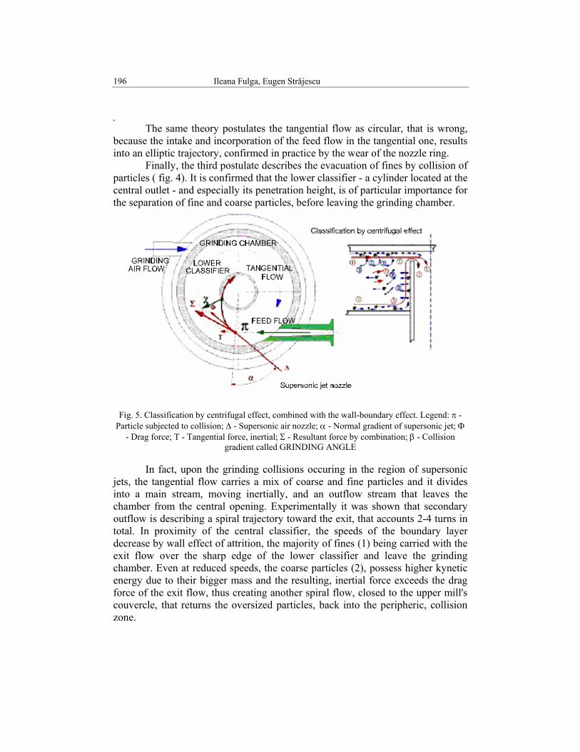
Finally, the third postulate describes the evacuation of fines by collision of particles ( fig. 4). It is confirmed that the lower classifier - a cylinder located at the central outlet - and especially its penetration height, is of particular importance for the separation of fine and coarse particles, before leaving the grinding chamber.
Fig. 5. Classification by centrifugal effect, combined with the wall-boundary effect. Legend: π -
Particle subjected to collision; Δ - Supersonic air nozzle; α - Normal gradient of supersonic jet; Φ - Drag force; T - Tangential force, inertial; Σ - Resultant force by combination; β - Collision
gradient called GRINDING ANGLE
In fact, upon the grinding collisions occuring in the region of supersonic jets, the tangential flow carries a mix of coarse and fine particles and it divides into a main stream, moving inertially, and an outflow stream that leaves the chamber from the central opening. Experimentally it was shown that secondary outflow is describing a spiral trajectory toward the exit, that accounts 2-4 turns in total. In proximity of the central classifier, the speeds of the boundary layer decrease by wall effect of attrition, the majority of fines (1) being carried with the exit flow over the sharp edge of the lower classifier and leave the grinding chamber. Even at reduced speeds, the coarse particles (2), possess higher kynetic energy due to their bigger mass and the resulting, inertial force exceeds the drag force of the exit flow, thus creating another spiral flow, closed to the upper mill's couvercle, that returns the oversized particles, back into the peripheric, collision zone.
Contributions to fluid dynamics in jetmills by a new aerodynamic model of supersonic flow 197
The classification effect of fines and coarse particles depends of many factors like the load of the mill, the density of the infeed material, the grinding angle, the working pressures, and also the physical dimensions of lower classifier, as well.
3. Commented example of a micronized powder
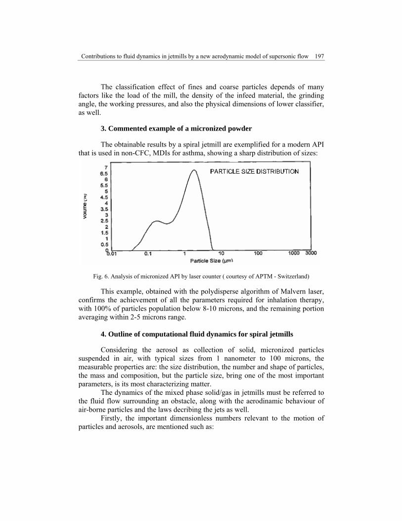
The obtainable results by a spiral jetmill are exemplified for a modern API that is used in non-CFC, MDIs for asthma, showing a sharp distribution of sizes:
Fig. 6. Analysis of micronized API by laser counter ( courtesy of APTM - Switzerland)
This example, obtained with the polydisperse algorithm of Malvern laser,
confirms the achievement of all the parameters required for inhalation therapy, with 100% of particles population below 8-10 microns, and the remaining portion averaging within 2-5 microns range.
4. Outline of computational fluid dynamics for spiral jetmills
Considering the aerosol as collection of solid, micronized particles
suspended in air, with typical sizes from 1 nanometer to 100 microns, the measurable properties are: the size distribution, the number and shape of particles, the mass and composition, but the particle size, bring one of the most important parameters, is its most characterizing matter.
The dynamics of the mixed phase solid/gas in jetmills must be referred to the fluid flow surrounding an obstacle, along with the aerodinamic behaviour of air-borne particles and the laws decribing the jets as well.
Firstly, the important dimensionless numbers relevant to the motion of particles and aerosols, are mentioned such as:
198 Ileana Fulga, Eugen Străjescu
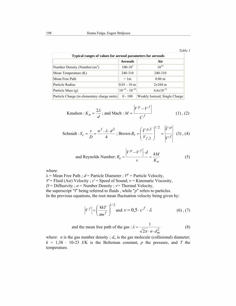
Table 1 Typical ranges of values for aerosol parameters for aerosols
Aerosols Air Number Density (Number/cm3) 100-105 1019 Mean Temperature (K) 240-310 240-310 Mean Free Path > 1m 0.06 m Particle Radius 0.01 - 10 m 2x10⁴ m Particle Mass (g) 10-18 - 10-19 4.6x10⁻²³ Particle Charge (in elementary charge units) 0 - 100 Weakly Ionized, Single Charge
Knudsen :d
Knλ2
= ; and Mach :f
fp
C
VVM
−= (1) , (2)
Schmidt :4
2dnDvS
fc
⋅⋅==
λ ; Brownf
p
f
pr
V
V
VVB
'
'2/1
2,
2,=⎟
⎟⎠
⎞⎜⎜⎝
⎛= (3) , (4)
and Reynolds Number:n
fp
e KM
v
dVVR 4
=⋅−
= (5)
where: λ = Mean Free Path ; d = Particle Diameter ; Vp = Particle Velocity, Vf = Fluid (Air) Velocity ; cf = Speed of Sound; ν = Kinematic Viscosity, D = Diffusivity ; n = Number Density ; v'= Thermal Velocity, the superscript "f" being referred to fluids , while "p" refers to particles. In the previous equations, the root mean fluctuation velocity being given by:
2/18
⎟⎟⎠
⎞⎜⎜⎝
⎛= f
f
mkTV
πand: λ⋅⋅= fcv 5,0 (6) , (7)
and the mean free path of the gas : 221
mdn ⋅⋅=
πλ (8)
where: n is the gas number density ; dm is the gas molecule (collisional) diameter; k = 1,38 ⋅ 10-23 J/K is the Boltzman constant, p the pressure, and T the temperature.
Contributions to fluid dynamics in jetmills by a new aerodynamic model of supersonic flow 199
For air, dm = 0.361nm and p
Tm
⋅=
1,23λ with p in Pa, and T in ºK (9)
5. Drag force and drag coefficient
A particle carried by a fluid is subjected to several hydrodynamic forces. For low Reynolds number flows, the Stokes drag force on a spherical particle is given by: dUFp ⋅⋅= μ3 , where d is the particle diameter, is the coefficient of viscosity and U the relative velocity of the fluid with respect to the particle.
This equation may be restated as:e
DD RAU
FC 24
21 2
=⋅⋅⋅
=ρ
(10)
where ρ is the fluid (air) density;
A is the cross sectional area of the spherical particle:4
2dA ⋅=π ;
and R is the Reynolds number: μ
ρ dURe⋅⋅
= .
The Stokes drag is applicable to the creeping flow regime (Stokes regime) with small Reynolds numbers (Re<0.5), but at higher Reynolds numbers, the drag coefficient deviates from equation (10).
Oseen included the inertial effect and developed a correction to the Stokes drag given as:
( )[ ]
e
eD R
RC
16/3124 +⋅= (11)
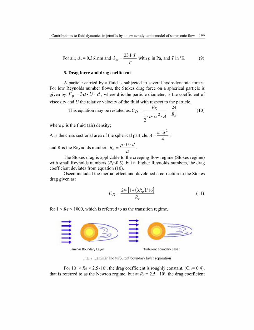
for 1 < Re < 1000, which is referred to as the transition regime.
Laminar Boundary Layer Turbulent Boundary Layer
Fig. 7. Laminar and turbulent boundary layer separation
For 103 < Re < 2.5 ⋅105, the drag coefficient is roughly constant. (CD = 0.4), that is referred to as the Newton regime, but at Re = 2.5 ⋅ 105, the drag coefficient
200 Ileana Fulga, Eugen Străjescu
decreases sharply due to the transition from laminar to turbulent boundary layer around the particle, that causes the separation point to shift downstream as shown below.
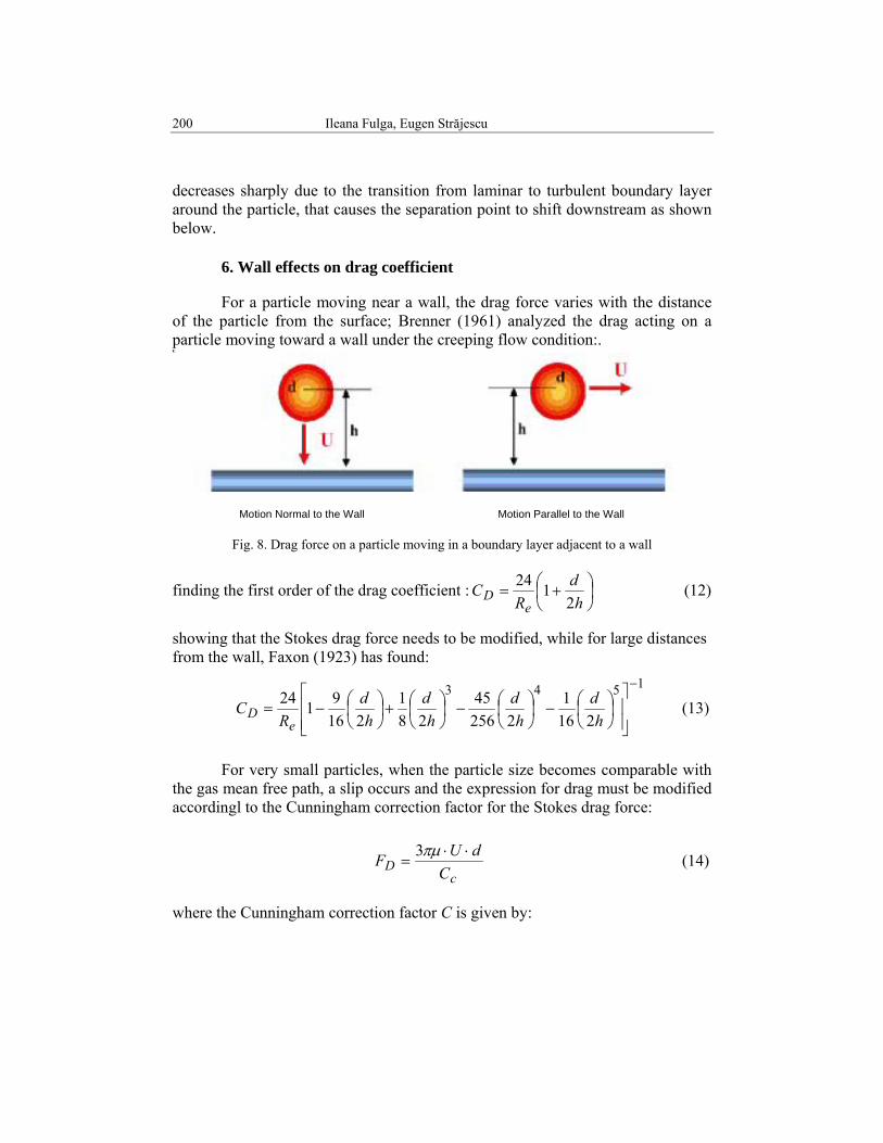
6. Wall effects on drag coefficient
For a particle moving near a wall, the drag force varies with the distance of the particle from the surface; Brenner (1961) analyzed the drag acting on a particle moving toward a wall under the creeping flow condition:. ¥.
Motion Normal to the Wall Motion Parallel to the Wall
Fig. 8. Drag force on a particle moving in a boundary layer adjacent to a wall
finding the first order of the drag coefficient : ⎟⎠⎞
⎜⎝⎛ +=
hd
RC
eD 2
124 (12)
showing that the Stokes drag force needs to be modified, while for large distances from the wall, Faxon (1923) has found:
1543
2161
225645
281
2169124
−
⎥⎥⎦
⎤
⎢⎢⎣
⎡⎟⎠⎞
⎜⎝⎛−⎟
⎠⎞
⎜⎝⎛−⎟
⎠⎞
⎜⎝⎛+⎟
⎠⎞
⎜⎝⎛−=
hd
hd
hd
hd
RC
eD (13)
For very small particles, when the particle size becomes comparable with
the gas mean free path, a slip occurs and the expression for drag must be modified accordingl to the Cunningham correction factor for the Stokes drag force:
c
D CdUF ⋅⋅
=πμ3 (14)
where the Cunningham correction factor C is given by:
Contributions to fluid dynamics in jetmills by a new aerodynamic model of supersonic flow 201
[ ]λλ 2/1,14,0257,121 dc e
dC ⋅−⋅+⋅
⋅+=
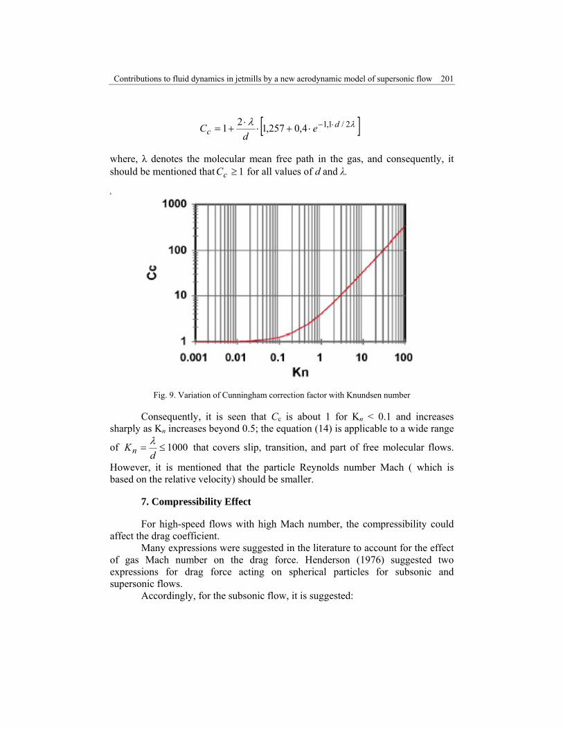
where, λ denotes the molecular mean free path in the gas, and consequently, it should be mentioned that 1≥cC for all values of d and λ. ¥.
Fig. 9. Variation of Cunningham correction factor with Knundsen number
Consequently, it is seen that Cc is about 1 for Kn < 0.1 and increases sharply as Kn increases beyond 0.5; the equation (14) is applicable to a wide range
of 1000≤=d
Knλ that covers slip, transition, and part of free molecular flows.
However, it is mentioned that the particle Reynolds number Mach ( which is based on the relative velocity) should be smaller.
7. Compressibility Effect
For high-speed flows with high Mach number, the compressibility could affect the drag coefficient.
Many expressions were suggested in the literature to account for the effect of gas Mach number on the drag force. Henderson (1976) suggested two expressions for drag force acting on spherical particles for subsonic and supersonic flows.
Accordingly, for the subsonic flow, it is suggested:
202 Ileana Fulga, Eugen Străjescu
⎥⎥⎦
⎤
⎢⎢⎣
⎡⎟⎟⎠
⎞⎜⎜⎝
⎛−−+
+⎥⎥⎦
⎤
⎢⎢⎣
⎡++
++
++⎟⎟⎠
⎞⎜⎜⎝
⎛−+
+⎭⎬⎫
⎩⎨⎧
⎥⎦
⎤⎢⎣
⎡⎟⎠
⎞⎜⎝
⎛−⋅++=
e
ee
ee
e
ecc
RM
MMRR
RRRM
SR
SRC
exp1
2,01,048,003,01
48,003,0(38,05,45,0exp
247,0exp567,133,424
82 (15)
8. Drag force acting spheric particles in subsonic flows
where M is the Mach number based on relative velocity, pVVV −=Δ and
( ) 2/γMS = is the molecular speed ratio, with γ the specific heat ratio. For the supersonic flows with Mach numbers equal or greater than 1,75,
the drag force is given by:
2/1
42
2/1
2
86,11
1058,12286,134,09,0
⎟⎟⎠
⎞⎜⎜⎝
⎛+
⎟⎟⎠
⎞⎜⎜⎝
⎛−++⎟⎟
⎠
⎞⎜⎜⎝
⎛++
=
e
eD
RM
SSSRM
MC (15)
For the flow regimes with Mach number between 1 and 1.75, a linear interpolation may be used. Carlson and Hoglund (1964) proposed the following expression:
⎥⎦
⎤⎢⎣
⎡⎟⎠
⎞⎜⎝
⎛−⋅+⋅+
⎟⎟⎠
⎞⎜⎜⎝
⎛−+
⋅=
MR
RM
MR
Ce
e
eD
25,1exp28,182,31
427,0exp124 63,4
(16)
9. Considerations on the free jet in stationary atmospheres
The literature presents many studies and experiments of free jets generated by nozzles into stationary atmospheres, or that moves axially, along the jet direction. The most important contributions are by Abramovitch [1], Schubauer and Then [2], combining a variety of information from different sources.
Contributions to fluid dynamics in jetmills by a new aerodynamic model of supersonic flow 203
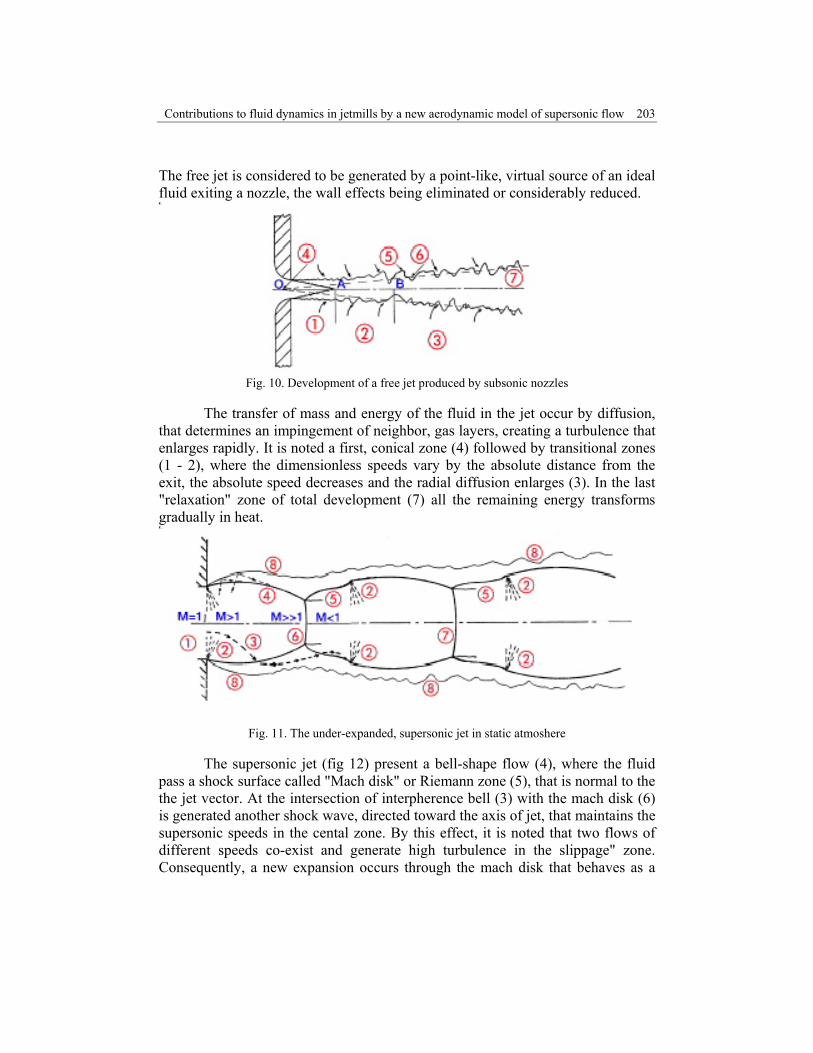
The free jet is considered to be generated by a point-like, virtual source of an ideal fluid exiting a nozzle, the wall effects being eliminated or considerably reduced. ¥.
Fig. 10. Development of a free jet produced by subsonic nozzles
The transfer of mass and energy of the fluid in the jet occur by diffusion,
that determines an impingement of neighbor, gas layers, creating a turbulence that enlarges rapidly. It is noted a first, conical zone (4) followed by transitional zones (1 - 2), where the dimensionless speeds vary by the absolute distance from the exit, the absolute speed decreases and the radial diffusion enlarges (3). In the last "relaxation" zone of total development (7) all the remaining energy transforms gradually in heat. ¥.
Fig. 11. The under-expanded, supersonic jet in static atmoshere
The supersonic jet (fig 12) present a bell-shape flow (4), where the fluid pass a shock surface called "Mach disk" or Riemann zone (5), that is normal to the the jet vector. At the intersection of interpherence bell (3) with the mach disk (6) is generated another shock wave, directed toward the axis of jet, that maintains the supersonic speeds in the cental zone. By this effect, it is noted that two flows of different speeds co-exist and generate high turbulence in the slippage" zone. Consequently, a new expansion occurs through the mach disk that behaves as a
204 Ileana Fulga, Eugen Străjescu
virtual nozzle, the process being repeated several times, less and less evident, until the peripheric speed of the jet is reduced enough, and the turbulences in slippage zone became stronger, the jet energy being diffused and transformed in heat.
The most precise theoretic elaboration of this phenomenon has been published by Love, Grinsby, Lee and Woodling [3] who indicated the methods of calculation the initial jet's shape and its axial speed.
Other works by Eglert [4], Hubbard [5] and Albini [6] offer more quick solutions, and all together have been considered in the developement of the new model of the spiral jetmills.
10. New aerodinamc model of supersonic flow in spiral jetmills
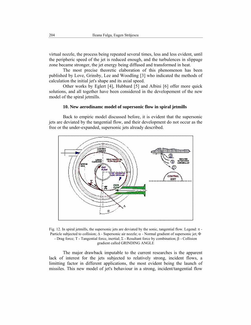
Back to empiric model discussed before, it is evident that the supersonic jets are deviated by the tangential flow, and their development do not occur as the free or the under-expanded, supersonic jets already described.
Fig. 12. In spiral jetmills, the supersonic jets are deviated by the sonic, tangential flow. Legend: π - Particle subjected to collision; Δ - Supersonic air nozzle; α - Normal gradient of supersonic jet; Φ
- Drag force; T - Tangential force, inertial; Σ - Resultant force by combination; β - Collision gradient called GRINDING ANGLE
The major drawback imputable to the current researches is the apparent lack of interest for the jets subjected to relatively strong, incident flows, a limitting factor in different applications, the most evident being the launch of missiles. This new model of jet's behaviour in a strong, incident/tangential flow
Contributions to fluid dynamics in jetmills by a new aerodynamic model of supersonic flow 205
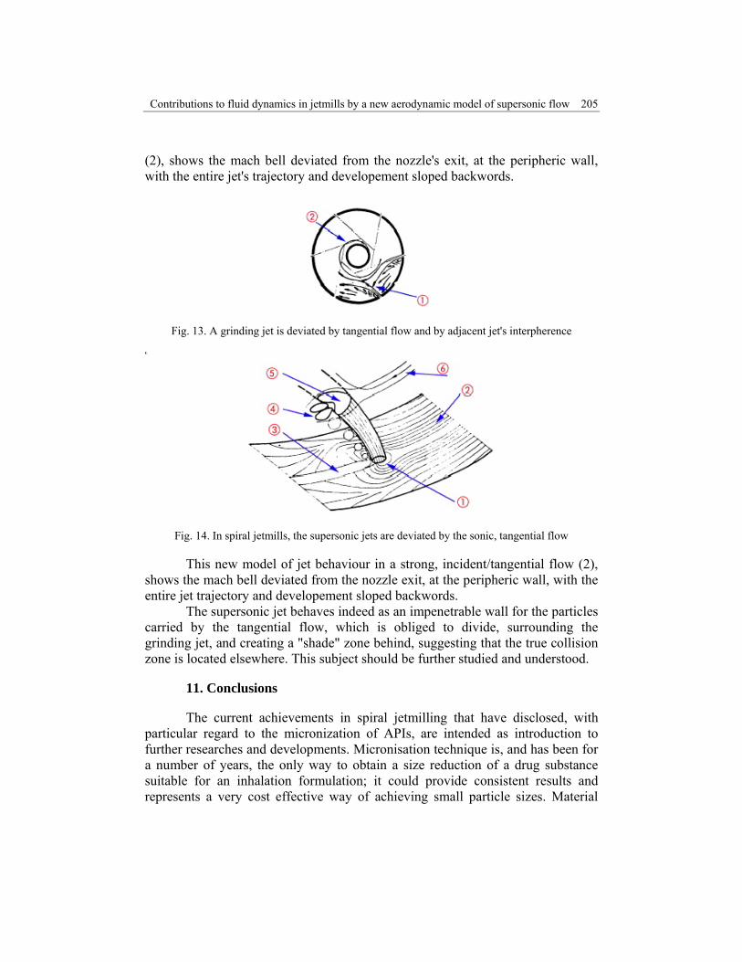
(2), shows the mach bell deviated from the nozzle's exit, at the peripheric wall, with the entire jet's trajectory and developement sloped backwords.
Fig. 13. A grinding jet is deviated by tangential flow and by adjacent jet's interpherence
¥.
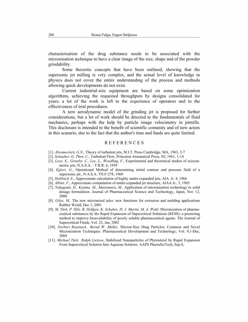
Fig. 14. In spiral jetmills, the supersonic jets are deviated by the sonic, tangential flow
This new model of jet behaviour in a strong, incident/tangential flow (2), shows the mach bell deviated from the nozzle exit, at the peripheric wall, with the entire jet trajectory and developement sloped backwords.
The supersonic jet behaves indeed as an impenetrable wall for the particles carried by the tangential flow, which is obliged to divide, surrounding the grinding jet, and creating a "shade" zone behind, suggesting that the true collision zone is located elsewhere. This subject should be further studied and understood.
11. Conclusions
The current achievements in spiral jetmilling that have disclosed, with particular regard to the micronization of APIs, are intended as introduction to further researches and developments. Micronisation technique is, and has been for a number of years, the only way to obtain a size reduction of a drug substance suitable for an inhalation formulation; it could provide consistent results and represents a very cost effective way of achieving small particle sizes. Material
206 Ileana Fulga, Eugen Străjescu
characterisation of the drug substance needs to be associated with the micronisation technique to have a clear image of the size, shape and of the powder grindability.
Some theoretic concepts that have been outlined, showing that the supersonic jet milling is very complex, and the actual level of knowledge in physics does not cover the entire understanding of the process and methods allowing quick developments do not exist.
Current industrial-size equipment are based on some optimization algorithms, achieving the requested throughputs by designs consolidated for years; a lot of the work is left to the experience of operators and to the effectiveness of trial procedures.
A new aerodynamic model of the grinding jet is proposed for further considerations, but a lot of work should be directed to the fundamentals of fluid mechanics, perhaps with the help by particle image velocimetry in jetmills. This disclosure is intended to the benefit of scientific comunity and of new actors in this scanario, due to the fact that the author's time and funds are quite limited.
R E F E R E N C E S
[1]. Abramovitch, G.N., Theory of turbulent jets, M.I.T. Press Cambridge, MA, 1963, 2-7 [2]. Schauber, G, Then, C., Turbulent Flow, Princeton Aronautical Press, NJ, 1961, 1-14 [3]. Love, E., Grinsby, C., Lee, L., Woodling, F., Experimental and theoretical studies of axisym-
metric jets, N.A.S.A. - T.R.R. 6, 1959 [4]. Eglert, G., Operational Method of determining initial contour and pressure field of a
supersonic jet., N.A.S.A. TN.F-278, 1960 [5]. Hubbard, E., Approximate calculation of highly under-expanded jets, AIA. Jr. 4, 1966 [6]. Albini, F., Approximate computation of under-expanded jet structure, AIAA Jr.. 3, 1965 [7]. Nakagami, H., Kojima, M., Matsumura, M., Application of micronization technology to solid
dosage formulation. Journal of Pharmaceutical Science and Technology, Japan, Nov 12, 2000
[8]. Giles, M., The new micronized talcs: new functions for extrusion and molding applications Rubber World, Dec 1, 2001
[9]. M. Türk, P. Hils, B. Helfgen, K. Schaber, H. J. Martin, M. A. Wahl, Micronization of pharma-ceutical substances by the Rapid Expansion of Supercritical Solutions (RESS): a promising method to improve bioavailability of poorly soluble pharmaceutical agents. The Journal of Supercritical Fluids, Vol. 22, Jan, 2002
[10]. Norbert Rasenack, Bernd W. Muller, Micron-Size Drug Particles: Common and Novel Micronization Techniques. Pharmaceutical Development and Technology, Vol. 9,1-Dec, 2004
[11]. Michael Türk, Ralph Lietzow, Stabilized Nanoparticles of Phytosterol by Rapid Expansion From Supercritical Solution Into Aqueous Solution. AAPS PharmSciTech, Sep 8,