building ion
TRANSCRIPT
BUILDING REABILITATION
Editors: M. Budescu N. Taranu I. Lungu
“Matei-Teiu Botez” Academic Society Publishing House
BUILDING REABILITATION Editors: M. Budescu
N. Taranu I. Lungu
“Matei-Teiu Botez” Academic Society Publishing House
Editors: Mihai Budescu, Nicolae Taranu, Irina Lungu Authors: Chapter 1: Mihai Budescu, Ioan Ciongradi Chapter 2: Ioan Ciongradi, Mihai Budescu Chapter 3: Mihai Budescu, Ioan Ciongradi Chapter 4: Nicolae Taranu Chapter 5: Irina Lungu, Mihai Budescu Chapter 6: Mihai Budescu, Ioan Ciongradi Chapter 7: Mihai Budescu, Ioan Ciongradi Chapter 8: Mihai Budescu, Anca-Mihaela Ciupala Chapter 9: Dorina Isopescu, Gabriel Oprisan Chapter 10: Dorina Isopescu Chapter 11: Ioan Gavrilas Translater: Roxana Craciun Descrierea CIP a Bibliotecii Naţionale a României Building rehabilitation / ed.: M. Budescu, N. Ţăranu. - Iaşi : Editura Societăţii Academice "Matei-Teiu Botez", 2003 Bibliogr. ISBN 973-7962-26-5 I. Budescu, Mihai (ed.) II. Ţăranu, Nicolae (ed.) 624
page 1
1 GENERALITIES
1.1 CONSTRUCTION REHABILITATION Construction rehabilitation means building up some of its functions, which were damaged during its service, and making them active again. Construction rehabilitation is a permanent concern for civil engineers due to the inevitable decay caused by material aging, which occurs in time and the effects of some accidental events. Thus, earthquakes, winds, slumps, fires, floods, explosions, chemical agents and fabrication processes are only some of the factors causing damages. Another cause occurring even more frequently is related to the dynamics of possible functional alterations. Very frequently, construction decay is caused by material aging in its various forms: its life time exceedence, fatigue, creep, yield, multiple load cycles or the action of the chemical agents. In many cases construction damages occur as a result of the degradation of the foundation soil caused by the rise of groundwater level, the lack of safety measures when dealing with collapsible or active soils, the infiltration of rain and industrial water or water infiltration caused by the defective maintenance of the water supply and sewing systems. Design errors should not be neglected either. There are cases when the designing engineer allows improper structural systems created by architects or when the beneficiary changes the destination of the building at a later stage engendering loading underestimation. Sometimes the designing process may be accompanied by conceptual errors referring to structure, modelling and calculus. Construction errors are also very frequent when using low quality materials or not complying with the project or technologies.
Building Rehabilitation
page 2
Shortcomings may occur when structural elements are stressed before reaching the appropriate strength of materials or when works are performed in cold weather conditions and without taking proper measures. Indirectly, buildings may also be damaged by a series of external factors such as: traffic expansion or the appearance of new buildings in the area and the degradation of infrastructure systems like pipe drains and water supply systems. In industry, various technological procedures accompanied by the release of aggressive chemical substances (e.g. chlorine, sulfur etc.) may hasten the degradation process particularly in the case of excessive humidity and the absence of any ventilation systems. Sometimes, technological alterations may lead to a rise in chemical aggressiveness or vibration level. There have also been detected many cases when degradation was caused by damaged equipment and industrial installations. However one of the most important causes of construction degradation is earthquake and the most vulnerable to its action are the old buildings where specific protection measures have not been taken. Sometimes the great number of earthquakes during the lifetime of a building lead to the loss of the bearing capacity due to material fatigue. Moreover, extraordinary unexpected seismic actions, which are unusual for the area, can cause the mass destruction of the building. One should not ignore the concept of ductile design, the basis of all modern design codes in seismic conditions, which admits the occurrence of structure degradation in certain areas in case of powerful earthquakes. Function alteration or changing the destination of the building, even when there are no damages, imposes structural rehabilitation so that the building service is preserved within safety limits. Structural rehabilitation may be achieved by:
i. changing the destination of the building; ii. replacing or partially altering the building; iii. local strengthening of structural elements; iv. altering the structural system.
All these ways of rehabilitation are strictly related to the condition of the building and the technical and economic possibilities of intervention. Changing the destination of the building is possible only when the structure is not seriously affected and safety requirements can be complied with by passing to a lower category of importance.
Generalities
page 3
Replacing or partially altering the building may mean permanently eliminating (one) part of the building (for example reducing the number of floors, keeping the facade only etc) or thoroughly recovering some parts of the damaged building if structure allows it. Consolidation or local strengthening (iii) may have good results when only some structural elements are damaged and require ordinary intervention measures. In this way, the structural system is not altered and the intervention is restricted only to build up the bearing capacity of the damaged elements. Structural system alteration may have several meanings, such as:
• introducing some adjacent construction elements which, together with the existing structure, make another structural system;
• changing the structural concept through other devices that can result in increasing the safety during service, like base isolation for structures, in seismic areas.
Structural rehabilitation consists of several stages:
i. the building appraisement, consisting of: - an evaluation of the condition of the structural system; - the diagnosis of the condition of the materials used; - the experimental diagnosis; - the analytic diagnoses of the structure
ii. establishing and designing the intervention measures iii. performing the structure rehabilitation (consolidation) iv. the experimental diagnosis of the rehabilitated system
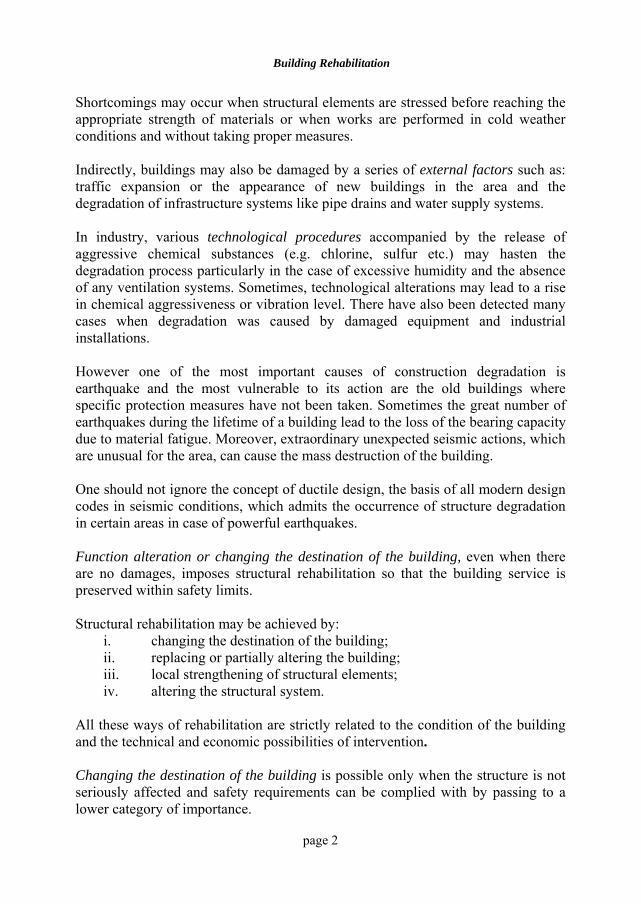
Some of these stages are not always compulsory, depending on the condition of the building, its importance, and interventions established by the experts. 1.2. CASE STUDIES Although technical literature describes various damaged buildings and interventions adopted for their rehabilitation, the authors will only discuss some representative examples they have encountered in their work. Concrete subjection to high temperature for a long period of time leads to its hastened aging and, consequently, the material becomes much more brittle. A very relevant example of this kind is the building of a board factory where furnaces were placed too close to the central column and no measures of thermal insulation were taken (fig.1.1). When a strong earthquake stroke, the columns broke down [1.1].
Building Rehabilitation
page 4
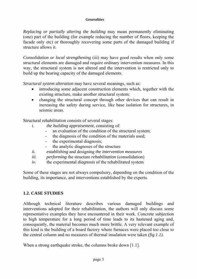
Currently, there are various types of industrial equipment producing vibrations and the lack of local isolation measures may weaken the joints between structural elements. An example that can be given for this case is the building of a chemical plant producing plastics [1.2]. For technological reasons, the recipient for the plastic barbotage was placed on the first floor of the building, fig.1.2.a. About 15 years later, the joints between the prefabricated elements weakened and, consequently, the vibration level in the structure increased, endangering the building. By using a scaffolding to support the recipient, whose foundation was separate from that of the structure, vibrations were completely eliminated. Adding some flexible bearings increased the equipment efficiency (fig.1.2.b).
FURNACES DAMAGED COLUMNS Fig.1.1 Concrete aging as a result of its subjection to high
temperatures for a long period of time
BARBOTAGERECIPIENT
SCAFFOLDING FLEXIBLEBEARINGS
a. b.
Fig.1.2 Aging as a result of the subjection to vibrations over a long period of time a. initial state b. solution adopted to eliminate the source of vibrations
Generalities
page 5
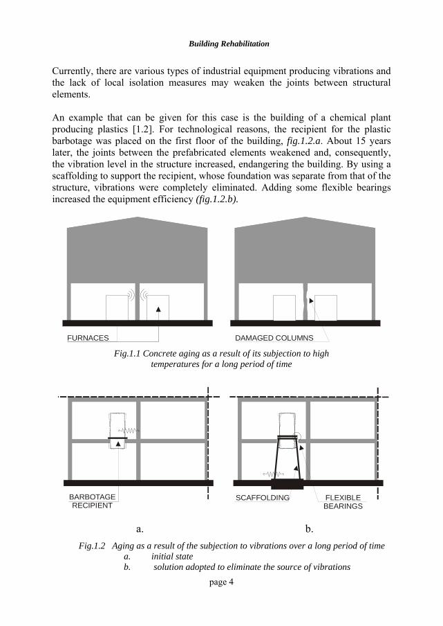
Serious building damages are encountered in industry, particularly in chemical industry. Gas release in a humid environment generates acids which, in contact with unprotected building elements, lead to their fast decay. However, from the construction viewpoint, the most serious effect is that produced by the loss or leachate of chemical substances in the sewing systems, which spread finally into the ground-water tables and begin attacking the structure from its foundation, fig.1.3 [1.3].
FOUNDATION AND COLUMNDAMAGED BY THE AGGRESSIVEGROUNDWATER
Fig.1.3 The effects of groundwater aggressiveness on the platform
of a pulp and paper plant
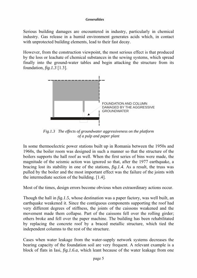
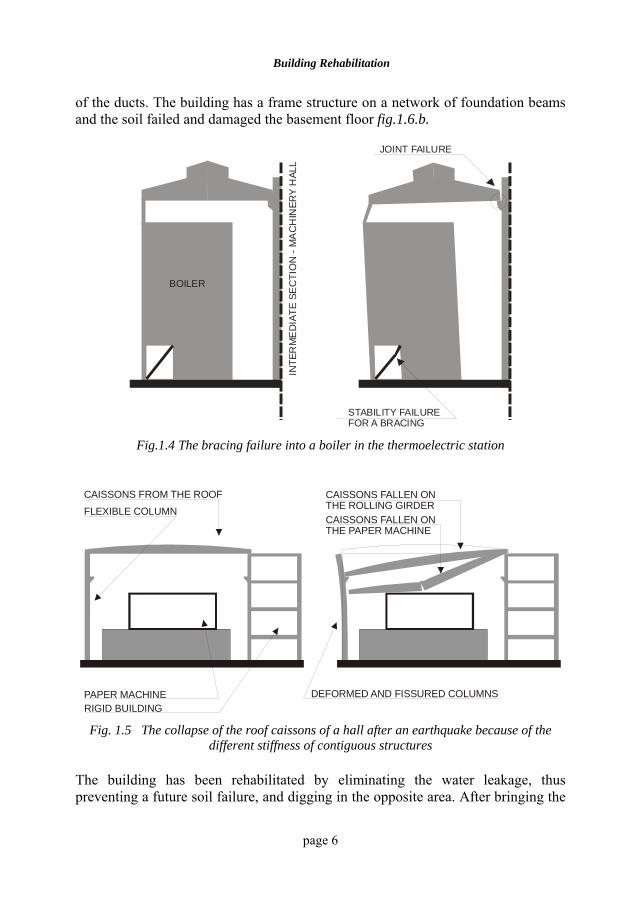
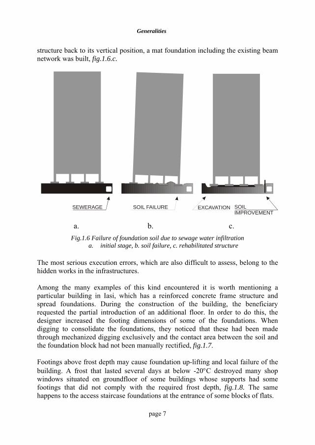
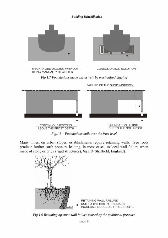
In some thermoelectric power stations built up in Romania between the 1950s and 1960s, the boiler room was designed in such a manner so that the structure of the boilers supports the hall roof as well. When the first series of bins were made, the magnitude of the seismic action was ignored so that, after the 1977 earthquake, a bracing lost its stability in one of the stations, fig.1.4. As a result, the truss was pulled by the boiler and the most important effect was the failure of the joints with the intermediate section of the building. [1.4]. Most of the times, design errors become obvious when extraordinary actions occur. Though the hall in fig.1.5, whose destination was a paper factory, was well built, an earthquake weakened it. Since the contiguous components supporting the roof had very different degrees of stiffness, the joints of the caissons weakened and the movement made them collapse. Part of the caissons fell over the rolling girder; others broke and fell over the paper machine. The building has been rehabilitated by replacing the concrete roof by a braced metallic structure, which tied the independent columns to the rest of the structure. Cases when water leakage from the water-supply network systems decreases the bearing capacity of the foundation soil are very frequent. A relevant example is a block of flats in Iasi, fig.1.6.a, which leant because of the water leakage from one
Building Rehabilitation
page 6
of the ducts. The building has a frame structure on a network of foundation beams and the soil failed and damaged the basement floor fig.1.6.b.
INTE
RM
ED
IATE
SE
CTI
ON
- M
AC
HIN
ERY
HAL
LBOILER
STABILITY FAILURE FOR A BRACING
JOINT FAILURE
Fig.1.4 The bracing failure into a boiler in the thermoelectric station
CAISSONS FALLEN ONTHE ROLLING GIRDER
PAPER MACHINERIGID BUILDING
FLEXIBLE COLUMNCAISSONS FROM THE ROOF
CAISSONS FALLEN ONTHE PAPER MACHINE
DEFORMED AND FISSURED COLUMNS
Fig. 1.5 The collapse of the roof caissons of a hall after an earthquake because of the different stiffness of contiguous structures
The building has been rehabilitated by eliminating the water leakage, thus preventing a future soil failure, and digging in the opposite area. After bringing the
Generalities
page 7
structure back to its vertical position, a mat foundation including the existing beam network was built, fig.1.6.c.
SEWERAGE SOIL FAILURE EXCAVATION SOIL IMPROVEMENT
a. b. c.
Fig.1.6 Failure of foundation soil due to sewage water infiltration a. initial stage, b. soil failure, c. rehabilitated structure
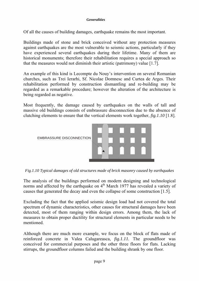
The most serious execution errors, which are also difficult to assess, belong to the hidden works in the infrastructures. Among the many examples of this kind encountered it is worth mentioning a particular building in Iasi, which has a reinforced concrete frame structure and spread foundations. During the construction of the building, the beneficiary requested the partial introduction of an additional floor. In order to do this, the designer increased the footing dimensions of some of the foundations. When digging to consolidate the foundations, they noticed that these had been made through mechanized digging exclusively and the contact area between the soil and the foundation block had not been manually rectified, fig.1.7.
Footings above frost depth may cause foundation up-lifting and local failure of the building. A frost that lasted several days at below -20°C destroyed many shop windows situated on groundfloor of some buildings whose supports had some footings that did not comply with the required frost depth, fig.1.8. The same happens to the access staircase foundations at the entrance of some blocks of flats.
Building Rehabilitation
page 8
MECHANIZED DIGGING WITHOUTBEING MANUALLY RECTIFIED
CONSOLIDATION SOLUTION
Fig.1.7 Foundations made exclusively by mechanized digging
CONTINUOUS FOOTINGABOVE THE FROST DEPTH
FAILURE OF THE SHOP WINDOWS
FOUNDATION LIFTINGDUE TO THE SOIL FROST
Fig.1.8 Foundations built over the frost level Many times, on urban slopes, establishments require retaining walls. Tree roots produce further earth pressure leading, in most cases, to local wall failure when made of stone or brick (rigid structures), fig.1.9 (Sheffield, England).
RETAINING WALL FAILURE DUE TO THE EARTH PRESSUREINCREASE INDUCED BY TREE ROOTS
Fig.1.9 Retaininging stone wall failure caused by the additional pressure
Generalities
page 9
Of all the causes of building damages, earthquake remains the most important. Buildings made of stone and brick conceived without any protection measures against earthquakes are the most vulnerable to seismic actions, particularly if they have experienced several earthquakes during their lifetime. Many of them are historical monuments; therefore their rehabilitation requires a special approach so that the measures would not diminish their artistic (patrimony) value [1.7]. An example of this kind is Lecompte du Nouy’s intervention on several Romanian churches, such as Trei Ierarhi, Sf. Nicolae Domnesc and Curtea de Arges. Their rehabilitation performed by construction dismantling and re-building may be regarded as a remarkable procedure; however the alteration of the architecture is being regarded as negative. Most frequently, the damage caused by earthquakes on the walls of tall and massive old buildings consists of embrassure disconnection due to the absence of clutching elements to ensure that the vertical elements work together, fig.1.10 [1.8].
EMBRASSURE DISCONNECTION
Fig.1.10 Typical damages of old structures made of brick masonry caused by earthquakes
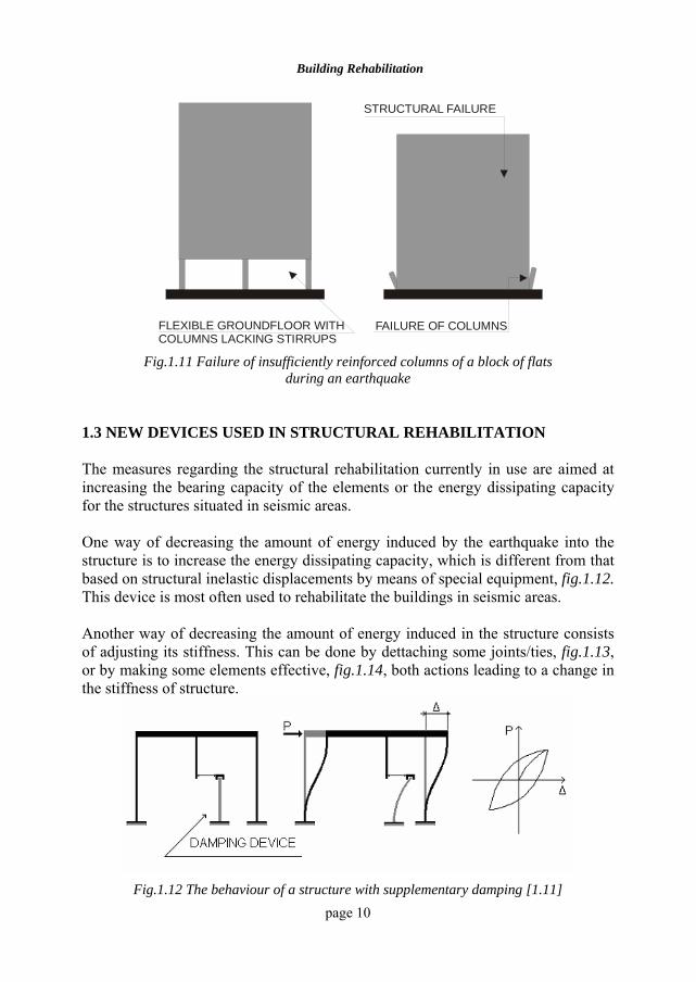
The analysis of the buildings performed on modern designing and technological norms and affected by the earthquake on 4th March 1977 has revealed a variety of causes that generated the decay and even the collapse of some construction [1.5]. Excluding the fact that the applied seismic design load had not covered the total spectrum of dynamic characteristics, other causes for structural damages have been detected, most of them ranging within design errors. Among them, the lack of measures to obtain proper ductility for structural elements in particular needs to be mentioned. Although there are much more example, we focus on the block of flats made of reinforced concrete in Valea Calugareasca, fig.1.11. The groundfloor was conceived for commercial purposes and the other three floors for flats. Lacking stirrups, the groundfloor columns failed and the building shrank by one floor.
Building Rehabilitation
page 10
FLEXIBLE GROUNDFLOOR WITHCOLUMNS LACKING STIRRUPS
FAILURE OF COLUMNS
STRUCTURAL FAILURE
Fig.1.11 Failure of insufficiently reinforced columns of a block of flats
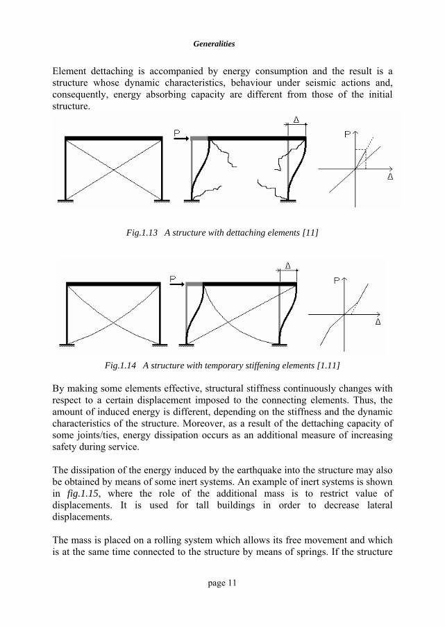
during an earthquake 1.3 NEW DEVICES USED IN STRUCTURAL REHABILITATION The measures regarding the structural rehabilitation currently in use are aimed at increasing the bearing capacity of the elements or the energy dissipating capacity for the structures situated in seismic areas. One way of decreasing the amount of energy induced by the earthquake into the structure is to increase the energy dissipating capacity, which is different from that based on structural inelastic displacements by means of special equipment, fig.1.12. This device is most often used to rehabilitate the buildings in seismic areas. Another way of decreasing the amount of energy induced in the structure consists of adjusting its stiffness. This can be done by dettaching some joints/ties, fig.1.13, or by making some elements effective, fig.1.14, both actions leading to a change in the stiffness of structure.
Fig.1.12 The behaviour of a structure with supplementary damping [1.11]
Generalities
page 11
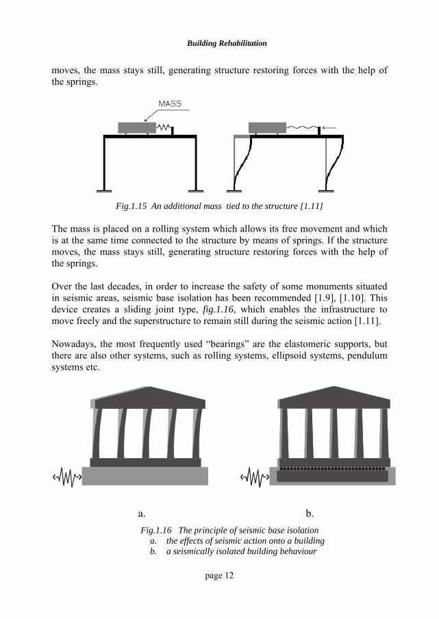
Element dettaching is accompanied by energy consumption and the result is a structure whose dynamic characteristics, behaviour under seismic actions and, consequently, energy absorbing capacity are different from those of the initial structure.
Fig.1.13 A structure with dettaching elements [11]
Fig.1.14 A structure with temporary stiffening elements [1.11]
By making some elements effective, structural stiffness continuously changes with respect to a certain displacement imposed to the connecting elements. Thus, the amount of induced energy is different, depending on the stiffness and the dynamic characteristics of the structure. Moreover, as a result of the dettaching capacity of some joints/ties, energy dissipation occurs as an additional measure of increasing safety during service. The dissipation of the energy induced by the earthquake into the structure may also be obtained by means of some inert systems. An example of inert systems is shown in fig.1.15, where the role of the additional mass is to restrict value of displacements. It is used for tall buildings in order to decrease lateral displacements. The mass is placed on a rolling system which allows its free movement and which is at the same time connected to the structure by means of springs. If the structure
Building Rehabilitation
page 12
moves, the mass stays still, generating structure restoring forces with the help of the springs.
Fig.1.15 An additional mass tied to the structure [1.11]
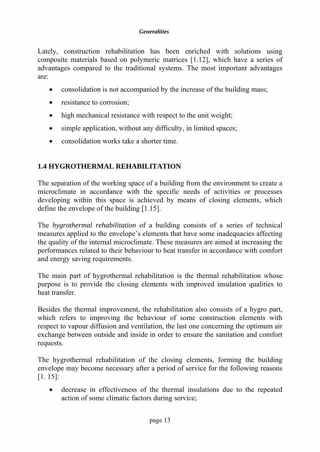
The mass is placed on a rolling system which allows its free movement and which is at the same time connected to the structure by means of springs. If the structure moves, the mass stays still, generating structure restoring forces with the help of the springs. Over the last decades, in order to increase the safety of some monuments situated in seismic areas, seismic base isolation has been recommended [1.9], [1.10]. This device creates a sliding joint type, fig.1.16, which enables the infrastructure to move freely and the superstructure to remain still during the seismic action [1.11]. Nowadays, the most frequently used “bearings” are the elastomeric supports, but there are also other systems, such as rolling systems, ellipsoid systems, pendulum systems etc.
a. b. Fig.1.16 The principle of seismic base isolation
a. the effects of seismic action onto a building b. a seismically isolated building behaviour
Generalities
page 13
Lately, construction rehabilitation has been enriched with solutions using composite materials based on polymeric matrices [1.12], which have a series of advantages compared to the traditional systems. The most important advantages are:
• consolidation is not accompanied by the increase of the building mass;
• resistance to corrosion;
• high mechanical resistance with respect to the unit weight;
• simple application, without any difficulty, in limited spaces;
• consolidation works take a shorter time. 1.4 HYGROTHERMAL REHABILITATION The separation of the working space of a building from the environment to create a microclimate in accordance with the specific needs of activities or processes developing within this space is achieved by means of closing elements, which define the envelope of the building [1.15]. The hygrothermal rehabilitation of a building consists of a series of technical measures applied to the envelope’s elements that have some inadequacies affecting the quality of the internal microclimate. These measures are aimed at increasing the performances related to their behaviour to heat transfer in accordance with comfort and energy saving requirements. The main part of hygrothermal rehabilitation is the thermal rehabilitation whose purpose is to provide the closing elements with improved insulation qualities to heat transfer. Besides the thermal improvement, the rehabilitation also consists of a hygro part, which refers to improving the behaviour of some construction elements with respect to vapour diffusion and ventilation, the last one concerning the optimum air exchange between outside and inside in order to ensure the sanitation and comfort requests. The hygrothermal rehabilitation of the closing elements, forming the building envelope may become necessary after a period of service for the following reasons [1. 15]:
• decrease in effectiveness of the thermal insulations due to the repeated action of some climatic factors during service;
Building Rehabilitation
page 14
• increase in exigency towards the inner hygrothermal microclimate according to the users’ high standards of hygiene and comfort;
• increase in exigency regarding the insulation level of the existing envelope after a period of service, for economic and energetic reasons
• request for a complete modernization determined by aesthetic, functional and resistance reasons etc. In this case, hygrothermal rehabilitation is simply a contextual yet absolutely necessary component of the total rehabilitation.
The basic principle of all the measures adopted to thermally rehabilitate the closing elements of a building [1.15] consists of increasing their resistance to thermal transfer by applying effective and long-lasting supplementary thermally insulating layers. For specific zones such as window pannels and unsealed joints of elements, hygrothermal rehabilitation may be performed based on other principles as well, but the main purpose remains the decrease in heat loss and consequently, in heat preservation. BIBLIOGRAPHY 1.1. Orlovschi, N., Leonte, C., Ionescu, C., Budescu, M., Efectul acţiunii
seismice a variaţiilor de temperatură asupra comportării unei structuri în cadre de beton armat, Simpozionul naţional - Interacţiunea construcţiilor cu mediul înconjurător V, 13, Iaşi octombrie 1978.
1.2 Ciongradi, I., Ionescu, C., Budescu, M., Reabilitarea sistemului de susţinere a convertorului de material plastic de pe platforma Săvineşti, Proiect I.P.Iaşi, 1980.
1.3 Mihul, A., Orlovschi, N., Budescu, M., Studiul răspunsului seismic al unor structuri speciale din industria hârtiei si celulozei, Combinatul din Brăila, Studiu I.P.Iaşi, 1977.
1.4 * * *, CET Borzeşti, Expertiză tehnică, ISPE, 2000. 1.5 * * *, Cutremurul de pământ din Romania de la 4 martie 1977, Editura
Academiei, 1982. 1.6 Ciongradi, I., Budescu, M., Biserica Evanghelică Iaşi, Proiect 1992. 1.7 Budescu, M., Ciongradi, I., Ciupală, A.M., Proposal of Intervention in
order to Rehabilitate The Resistance Structure Of "Trei Ierarhi" Monastery" Buletinul I.P.Iaşi, Tomul XL (XLIV), Fasc. 1-4, 1994.
1.8 Negoita, Al., Aur, V., Budescu, M., Comportarea materialelor şi a construcţiilor din zidarie portantă din municipiul Iaşi, Buletinul I.P.Iaşi, Tomul XXIV (XXVIII), Fasc.3-4, 1979.
Generalities
page 15
1.9 Skinner, R.I, Robinson, W.H., McVerry, G.H., An Introduction to Seismic Isolation, John Wiley & Sons, England, 1993
1.10 Kelly, J.M., Earthquake-resistant Design with Rubber, 2nded., Spriner-Verlag, London, 1997.
1.11 Budescu, M., Contributii privind izolarea seismică a structurilor , teza de doctorat , Institutul Politehnic Gheorghe Asachi Iasi , 1984.
1.12 Tăranu, N., Isopescu, D. – Structures Made of Composite Materials, Editura Vesper, Iaşi, 1996.
1.13 Neale, K.W, Labossiere, P., Advanced Composite Materials in Bridges and Structures”, 1st International Conference, Ed. Quebec, 1992.
1.14 Crasto, A.S., Kim, R.Y., Mistretta, J.P., Rehabilitation of concrete bridge beams with externally-bonded composite plates. Part II - International SAMPE Symposium and Exhibition (Proceedings), Vol.41, 1996.
1.15 Gavrilaş, I., Fizica construcţiilor. Reabilitarea higrotermicã a clădirilor. Editura Cermi, Iaşi, 1999.
page 16
2 STRUCTURAL ASSESSMENT
OF BUILDINGS
2.1 THE NEED FOR ASSESSMENT There are many situations when the owner, the beneficiary and the administrator of a building has the obligation or the desire to know about the condition of the building and assess its ability to resist various actions, especially when degradation affects the structure due to aging or when certain functional or technological changes require some intervention. Assessing the condition of a building requires a skillful expert. This expert is a very well trained specialist, officially certified and authorised by public authority. Every assessment ends with an assessment report including the expert’s findings, conclusions and suggestions regarding the condition of the building and the most appropriate intervention decisions that the beneficiary needs to make. Here are the most frequent situations when assessment is necessary: i. a change in the destination of the building or of one of its parts/rooms caused by:
- alterations in the layout (arranging or making basements, over-storeys and attics, making or eliminating holes within the structural, stiffening, closing or dividing walls)
- replacing/improving the technological process in industrial buildings, changing and/or replacing the equipment, altering the net load, changing the characteristics of the equipment, increasing the vibration level, changing the installation routes etc.
ii. the occurrence of flaws in the structure due to designing errors, defective execution, the inappropriate service conditions or maintenance of the building as well as the degradation and differential settlements of the foundation soil, corrosion, condense, frost and thaw phenomena, high differences in temperature, changes in the strength and deformation capacity of the building materials over time, the effects of material fatigue and aging, vibrations and traffic;
Structural assessment of buildings
page 17
iii. the user’s or the public authority inspectors’ observance of the cases when some structural elements are undersized or service loads are actually bigger than the considered design loads; iv. the occurrence of certain circumstances when other buildings or technologies close to the building of interest may cause various damages (for example, a damaged water tower may fall over the neighbouring buildings); v. the occurrence of important damages due to natural calamities (strong winds, floods, landslides, mine or cave subsidency, earthquakes) or other causes (fires, explosions). The buildings located in seismic areas are a special case. In many countries, the norms for this type of buildings require that the owners should assess the condition of the structures that had been exposed to strong earthquakes. These assessments establish the building safety level according to the current design codes and possible intervention measures to increase safety in case of earthquakes. The seismic rehabilitation of historical buildings must be preceded by an elaborate documentary work, by the careful evaluation of the buildings and their site as well as by a thorough planning of the whole rehabilitation process. All these provide information about the history of the buildings, their former inhabitants, the utilities they used over time and which is the most important, they provide clues about what needs to be repaired and what needs to be kept as before, during the rehabilitation operation and about the elements allowing intervention. Research consists of studying the history of the building and its evolution in time by means of written documents and photos. Then, the building is examined by taking photos of its interior, its exterior and its construction site. The initial materials, their characteristics, the finishing etc. as well as their alteration in time are also evaluated. These alterations may sometimes be part of the historical character of the building so they must be carefully analysed before starting the rehabilitation operation to decide what elements need repairing and what elements need replacing. The rehabilitation process starts with the design activity that selects the materials, the characteristics and the finishings which need to be protected during the operation and decides upon the logic order of activities required by the rehabilitation operation. Protecting a historical construction is partly based on preserving the building materials and the characteristics, maintaining the historical nature and architectural
Building Rehabilitation
page 18
features of the entire building. These features differ from one building to another and it refers to materials (stone, brick, wood, plaster, brass), external characteristics (porches, decorative elements, windows, roofs), interiors (entrance halls, rooms). To sum up, the rehabilitation operation begins only after all important materials and characteristics that need to be preserved during the process have been identified. 2.2 METHODS OF ASSESSING THE CONDITION OF EXISTING
BUILDINGS 2.2.1 Evaluation stages The technical literature presents various methods used to evaluate the condition of the existing buildings [2.1], [2.2], [2.3], [2.4], [2.5] grounded on the following principles: a. the assessment of a building condition is done in successive and more and
more complex stages to get a thorough and accurate picture of the existing and working conditions of the structural and non-structural elements of the building;
b. the evaluation operation is generally developed on several levels:
• gathering the initial information from the analysis of the existing documents referring to the building and the technical prescriptions in use at the time of its execution, surveys;
• the preliminary qualitative evaluation through direct observation (in situ), visual analyses and inspections on the construction site;
• the additional qualitative evaluation, more detailed and achieved by sampling, uncoverings etc.;
• the preliminary approximate analytical evaluation; • the detailed analytical evaluation;
c. the above-mentioned evaluation procedures may be approached independently – one by one – or successively, in groups of two or more, depending on the information and data obtained in the previous stages.
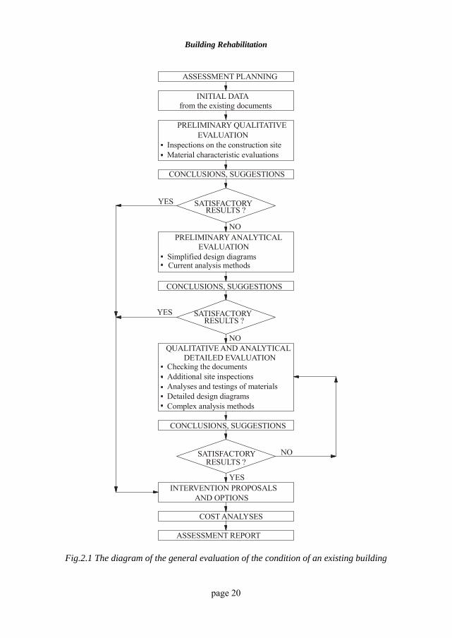
As shown in fig.2.1, the operation begins with gathering the initial data, followed by the preliminary qualitative evaluation and, if necessary, by the preliminary analytic evaluation.
Initial evaluation provides the first series of data related to the condition of the building and of the structure, on which the expert and/or the beneficiary can decide
Structural assessment of buildings
page 19
to continue with the further detailed evaluation. It should be mentioned that when making this decision, they also need to consider the preservation degree foreseen for the building being assessed. Evaluation results are written down in an assessment report including the recommendations and suggestions related to the intervention (for example, repairs, strengthening, changing the destination of the building, partial or thorough demolition) and, if requested, studies on the intervention cost. Successive application of more and more refined evaluation procedures (named “filters”) defines a new investigation method for the structural assessment of buildings - “the screening method”. 2.2.2 Initial Data Initial data come from the information gathered by analysing the existing documents, which are either in the beneficiary’s, the designer’s or the archives’ possession: the initial project, the book of the building, the geotechnical report, the data base concerning the monitoring of the building behaviour, information provided by the administration concerning the building service and behaviour during the previous earthquakes or other accidental actions. Initial data will include:
• the time of design and errection of the building, the names of the designers and contractors;
• the destination and the site of the building;
• the description of the building – spans, bays, number of storeys, structure and the geometric dimensions of the main structural elements, dividing and closing systems, building services, finishings;
• the extent to which the project complies with the current prescription regarding the errection of the building;
• the description of the technology used, the duration and technological stages;
• the building service period, any interventions, repairs or alterations made on it, any disturbances, variations or special events during its service, etc.;
• the characteristics of the materials used in the project (for concrete – grade or class, aggregate grading, cement type and quality, preparation method etc., for reinforcement – steel grade and type, steel characteristics from the
Building Rehabilitation
page 20
ASSESSMENT PLANNING
INITIAL DATA
PRELIMINARY QUALITATIVE
PRELIMINARY ANALYTICAL
QUALITATIVE AND ANALYTICALDETAILED EVALUATION
CONCLUSIONS, SUGGESTIONS
CONCLUSIONS, SUGGESTIONS
CONCLUSIONS, SUGGESTIONS
INTERVENTION PROPOSALS
COST ANALYSES
ASSESSMENT REPORT
AND OPTIONS
RESULTS ?
RESULTS ?
RESULTS ?
YES
YES
NO
NO
YES
NO
SATISFACTORY
SATISFACTORY
SATISFACTORY
EVALUATION
EVALUATION
Inspections on the construction site
Simplified design diagrams
Checking the documentsAdditional site inspectionsAnalyses and testings of materialsDetailed design diagramsComplex analysis methods
Material characteristic evaluations
Current analysis methods
from the existing documents
Fig.2.1 The diagram of the general evaluation of the condition of an existing building
Structural assessment of buildings
page 21
suppliers’ bulletins and site tests etc., for the steel in metallic products – steel grade and type, suppliers, laboratory test bulletins, welds etc.)
• a brief presentation of the geotechnical report. 2.2.3 Qualitative evaluation The qualitative evaluation of a building is the first assessment stage and consists of an inspection on the construction site in order to identify its structure, the damage/degradation/flaws and their causes. This evaluation regards aspects like preserving the destination and the importance of the building, the seismic area where it is situated and the actions to which it is subjected. According to these aspects, several types of buildings can be identified. There are buildings which definitely have the required safety level, others which certainly have a seismic risk and need to be examined through analytic methods. The qualitative evaluation is based on the architectural and structural design of the building. When these are not available, the assessment is based on the surveys made during the evaluation process. There are circumstances when structural elements are not visible as they are hidden by finishings and insulating systems. Therefore, the operation requires uncoverings to identify the structural elements. Generally, the elements that need identification are the following:
• vertical elements: plain concrete, reinforced concrete or masonry columns and walls;
• main and secondary elements of the floors: plates, belts, beams and girders
• roofing elements;
• prefabs and their joining;
• bracing systems;
• stairs and staircases;
• closing and dividing elements;
• the foundation system;
• finishing and coating elements if they are fixed to the structural elements.
All these elements need to be identified and surveyed at the same time. The survey is a brief one if technical documentation is available and a more detailed one if the
Building Rehabilitation
page 22
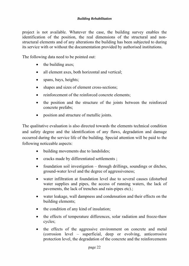
project is not available. Whatever the case, the building survey enables the identification of the position, the real dimensions of the structural and non-structural elements and of any alterations the building has been subjected to during its service with or without the documentation provided by authorised institutions. The following data need to be pointed out:
• the building axes;
• all element axes, both horizontal and vertical;
• spans, bays, heights;
• shapes and sizes of element cross-sections;
• reinforcement of the reinforced concrete elements;
• the position and the structure of the joints between the reinforced concrete prefabs;
• position and structure of metallic joints. The qualitative evaluation is also directed towards the elements technical condition and safety degree and the identification of any flaws, degradation and damage occurred during the service life of the building. Special attention will be paid to the following noticeable aspects:
• building movements due to landslides;
• cracks made by differentiated settlements ;
• foundation soil investigation – through drillings, soundings or ditches, ground-water level and the degree of aggressiveness;
• water infiltration at foundation level due to several causes (disturbed water supplies and pipes, the access of running waters, the lack of pavements, the lack of trenches and rain-pipes etc).;
• water leakage, wall dampness and condensation and their effects on the building elements;
• the condition of any kind of insulation;
• the effects of temperature differences, solar radiation and freeze-thaw cycles;
• the effects of the aggressive environment on concrete and metal (corrosion level – superficial, deep or evolving, anticorrosive protection level, the degradation of the concrete and the reinforcements
Structural assessment of buildings
page 23
obtained through corrosion, the condition of the reinforcement covering etc);
• the effects of some biological factors (for example, the existence of certain fungi in wood structures);
• element, section or joint eccentricities ;
• the lack of certain structural elements;
• the effects of earthquake, accidents, damage, explosions, fire (element or spar failure, spar buckling, element and structure movements or high distortions, large cracks in the reinforced concrete or masonry elements, metallic joint degradation due to the lack of certain joint pieces, of incomplete or defective welds or screws or because of insufficient screwing etc.);
• the building deformation level, which can be found out through topometric measurements as well;
• the concrete condition as a result of the degradation caused by wear and accidental blows and the reinforcement protection.
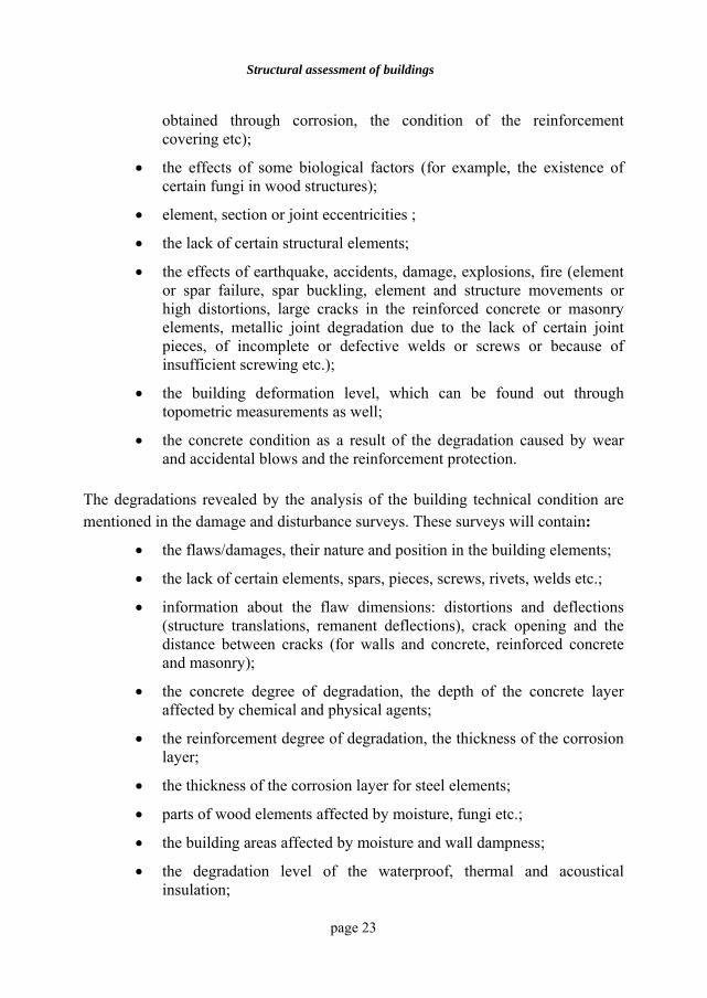
The degradations revealed by the analysis of the building technical condition are mentioned in the damage and disturbance surveys. These surveys will contain:
• the flaws/damages, their nature and position in the building elements;
• the lack of certain elements, spars, pieces, screws, rivets, welds etc.;
• information about the flaw dimensions: distortions and deflections (structure translations, remanent deflections), crack opening and the distance between cracks (for walls and concrete, reinforced concrete and masonry);
• the concrete degree of degradation, the depth of the concrete layer affected by chemical and physical agents;
• the reinforcement degree of degradation, the thickness of the corrosion layer;
• the thickness of the corrosion layer for steel elements;
• parts of wood elements affected by moisture, fungi etc.;
• the building areas affected by moisture and wall dampness;
• the degradation level of the waterproof, thermal and acoustical insulation;
Building Rehabilitation
page 24
• the degradation level of any kind of installation. When the physical, chemical and mechanical characteristics of materials need to be checked as well and the elements show no decay, the characteristic values established in the project can be used. Otherwise, experiments will be made to identify these properties, the reinforcement position within the reinforced concrete elements, the quality of the welds etc. Technical literature (see chapter 3) minutely presents the methodology of non-destructive and destructive tests on site and in laboratory, describing the necessary equipment, and how to assess the results. Many of the technical reports are also devoted to determine the corrosive effect of the aggressive environment on building elements and to predict corrosion’s likely evolution in time. Other types of experiments are used to determine the dynamic characteristics of the buildings. It is well known that material structure changes over time and possible decays may weaken or even eliminate/destroy the joints between structural elements. Changes may also occur in the interaction process between structure and non-structural elements and between foundation and foundation soil. All these aspects show that in many cases it is necessary to establish the altered/modified vibration periods and damping characteristics through experiments. If the data contained in the initial geotechnical report are not relevant or simply not enough, or if changes have been detected within the foundation soil structure due to the underground water rise, migration or flow, to the rain water leakage or to losses from ducts, then the geotechnical report must be remade. Thus, a new set of ground investigations based on drilling (sounding) or excavating procedures according to the nature of the soil and the importance of the building are performed and the results are concluded into the new geotechnical report. In accordance with the various qualitative assessment methodologies, analysis results may be digested, wrote down and consigned in various document or form types including a synthesis of the findings on the structural and non-structural elements. Finally, the building may be given a grade representing its bearing capacity or its degree of risk/safety. 2.2.4 Analytic Evaluation Along with decision data, preliminary qualitative evaluation also provides the initial data for a further more minute analysis based on calculus.
Structural assessment of buildings
page 25
Preliminary analytic evaluation more accurate than the qualitative evaluation – is based on determining the ratio between available generalised force and necessary generalised force that should be supported by the building, the element or the section according to the current design codes at the moment when the assessment is made. These ratios have various names, such as coefficient of seismic capacity or degree of safety under seismic actions or other actions. A generalised force in the expression of the above mentioned ratio may be the total (base) shear force for the entire structure, effort and/or stress for individual elements and typical cross-sections. These ratios may also be expressed by absolute deflections or relative displacements. The lowest values accepted for structural safety assessment reports are mentioned in the codes and they generally depend on the building category/class of importance. The closer to (or bigger than) 1 the values mentioned in the reports, the better the load bearing capacity of the building. Structure modelling according to loading cases, mass and stiffness is achieved through simplified representations for each principal axis of the building or “stick” models or storey stiffness models (roughly taking into account the influence of the torsion effect). The structural analysis will be carried out for gravity loads, climatic and seismic loads using the actual magnitudes/loads, geometry and cross-sections found in the structural survey and considering all existing damages and flaws. The bearing capacity of the characteristic cross-sections is determined using the dimensions given by the surveys and the present values of strength found out experimentally. If no damages are found, the initial design values are accepted. The detailed analytic assessment is based on using 3D-calculus models with concentrated masses or finite elements, which can reveal and accordingly consider both the structural damaged areas and the non-linear behaviour of the building materials. The seismic action may be given by an accelerogram or a set of accelerograms recorded from real earthquakes or acceleration spectra specially drawn for the given site. In this case, the effective ductility of the structural elements independently and of the entire structure can also be determined. 2.3. ASSESSMENT REPORT A building assessment ends with a document called assessment report, which generally consists of the following chapters:
Building Rehabilitation
page 26
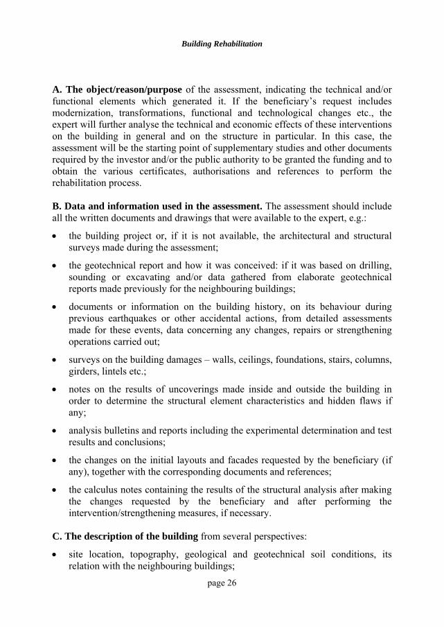
A. The object/reason/purpose of the assessment, indicating the technical and/or functional elements which generated it. If the beneficiary’s request includes modernization, transformations, functional and technological changes etc., the expert will further analyse the technical and economic effects of these interventions on the building in general and on the structure in particular. In this case, the assessment will be the starting point of supplementary studies and other documents required by the investor and/or the public authority to be granted the funding and to obtain the various certificates, authorisations and references to perform the rehabilitation process. B. Data and information used in the assessment. The assessment should include all the written documents and drawings that were available to the expert, e.g.:
• the building project or, if it is not available, the architectural and structural surveys made during the assessment;
• the geotechnical report and how it was conceived: if it was based on drilling, sounding or excavating and/or data gathered from elaborate geotechnical reports made previously for the neighbouring buildings;
• documents or information on the building history, on its behaviour during previous earthquakes or other accidental actions, from detailed assessments made for these events, data concerning any changes, repairs or strengthening operations carried out;
• surveys on the building damages – walls, ceilings, foundations, stairs, columns, girders, lintels etc.;
• notes on the results of uncoverings made inside and outside the building in order to determine the structural element characteristics and hidden flaws if any;
• analysis bulletins and reports including the experimental determination and test results and conclusions;
• the changes on the initial layouts and facades requested by the beneficiary (if any), together with the corresponding documents and references;
• the calculus notes containing the results of the structural analysis after making the changes requested by the beneficiary and after performing the intervention/strengthening measures, if necessary.
C. The description of the building from several perspectives:
• site location, topography, geological and geotechnical soil conditions, its relation with the neighbouring buildings;
Structural assessment of buildings
page 27
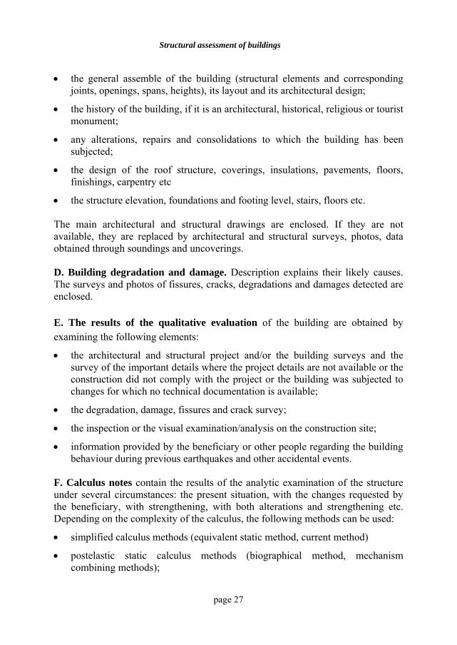
• the general assemble of the building (structural elements and corresponding joints, openings, spans, heights), its layout and its architectural design;
• the history of the building, if it is an architectural, historical, religious or tourist monument;
• any alterations, repairs and consolidations to which the building has been subjected;
• the design of the roof structure, coverings, insulations, pavements, floors, finishings, carpentry etc
• the structure elevation, foundations and footing level, stairs, floors etc. The main architectural and structural drawings are enclosed. If they are not available, they are replaced by architectural and structural surveys, photos, data obtained through soundings and uncoverings. D. Building degradation and damage. Description explains their likely causes. The surveys and photos of fissures, cracks, degradations and damages detected are enclosed. E. The results of the qualitative evaluation of the building are obtained by examining the following elements:
• the architectural and structural project and/or the building surveys and the survey of the important details where the project details are not available or the construction did not comply with the project or the building was subjected to changes for which no technical documentation is available;
• the degradation, damage, fissures and crack survey;
• the inspection or the visual examination/analysis on the construction site;
• information provided by the beneficiary or other people regarding the building behaviour during previous earthquakes and other accidental events.
F. Calculus notes contain the results of the analytic examination of the structure under several circumstances: the present situation, with the changes requested by the beneficiary, with strengthening, with both alterations and strengthening etc. Depending on the complexity of the calculus, the following methods can be used:
• simplified calculus methods (equivalent static method, current method)
• postelastic static calculus methods (biographical method, mechanism combining methods);
Building Rehabilitation
page 28
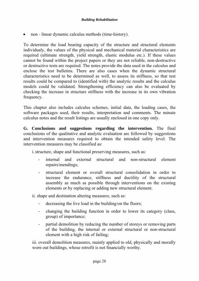
• non - linear dynamic calculus methods (time-history). To determine the load bearing capacity of the structure and structural elements individualy, the values of the physical and mechanical material characteristics are required (ultimate strength, yield strength, elastic modulus etc.). If these values cannot be found within the project papers or they are not reliable, non-destructive or destructive tests are required. The notes provide the data used in the calculus and enclose the test bulletins. There are also cases when the dynamic structural characteristics need to be determined as well, to assess its stiffness, so that test results could be compared to (identified with) the analytic results and the calculus models could be validated. Strengthening efficiency can also be evaluated by checking the increase in structure stiffness with the increase in its own vibration frequency. This chapter also includes calculus schemes, initial data, the loading cases, the software packages used, their results, interpretation and comments. The minute calculus notes and the result listings are usually enclosed in one copy only. G. Conclusions and suggestions regarding the intervention. The final conclusions of the qualitative and analytic evaluation are followed by suggestions and intervention measures required to obtain the intended safety level. The intervention measures may be classified as:
i. structure, shape and functional preserving measures, such as:
- internal and external structural and non-structural element repairs/mendings;
- structural element or overall structural consolidation in order to increase the endurance, stiffness and ductility of the structural assembly as much as possible through interventions on the existing elements or by replacing or adding new structural element.
ii. shape and destination altering measures, such as:
- decreasing the live load in the building/on the floors;
- changing the building function in order to lower its category (class, group) of importance;
- partial demolition by reducing the number of storeys or removing parts of the building, the internal or external structural or non-structural element with a high risk of failing;
iii. overall demolition measures, mainly applied to old, physically and morally worn out buildings, whose retrofit is not financially worthy.
Structural assessment of buildings
page 29
The expert presents the suggested measures and the solutions which are to be detailed in the intervention project (repairs, strengthening, or demolition). These measures are tested by calculus to confirm the increase in safety under exterior actions at least to the level required by official norms. If requested, the expert will also present the estimated economic documentation of the costs involved in the intervention measures. In the end, the decision concerning the intervention, positioning and work stages belongs to the beneficiary, the owner or the investor who, together with the public authority representatives (if any) may consider other intervention criteria as well (urban character, land value, the importance of the building as a historical monument etc.) or may decide to perform other works as well, such as:
• functional and technological change or modernization;
• finishing, closing, division and floor improvements;
• insulation and installation changes. BIBLIOGRAPHY 2.1 Pielert, J., Baumert, C. and Green, M., “ASCE Standards on Structural
Condition Assessment and Rehabilitation of Buildings”, Standards for Preservation and Rehabilitation, ASTM STP 1258, S.J. Kelley, Ed., American Society for Testing and Materials, 1996, pp. 126-136.
2.2 Culver, Ch., Lew, H.S., Hart, G.C. and Pinkham, C., “Natural Hazards Evaluation of Existing Buildings”, National Bureau of Standards, U.S.A., 1975.
2.3 Okada, T. and Bresler, B., “Strength and Ductility Evaluation of Existing Low-Risc Reinforced Concrete Buildings-Screening Method”, EERC 76-1, University of California, Berkeley, 1976.
2.4 Hirosawa, M., “Evaluation Methods of Earthquake Resistant Properties of Existing Reinforced Concrete Buildings”, Japanese National Committee for Earthquake Engineering”, Tokyo, 1976.
2.5 Asociaţia Inginerilor Constructori din România, AICR, “Metoda de determinare a capacităţii portane la solicitări gravitaţionale şi seismice a construcţiilor din fondul existent, cu propuneri de măsuri pentru reducerea gradului de risc", Bucureşti, 1990.
page 30
3 SYSTEMS AND EQUIPMENT USED IN
STRUCTURE DIAGNOSIS 3.1 GENERAL ASPECTS The diagnosis made to determine the construction condition involves experimental determinations on three levels:
i. the building material;
ii. the structural member;
iii. the entire building. To determine the characteristics of the materials used in construction two methods are used:
• non-destructive methods,
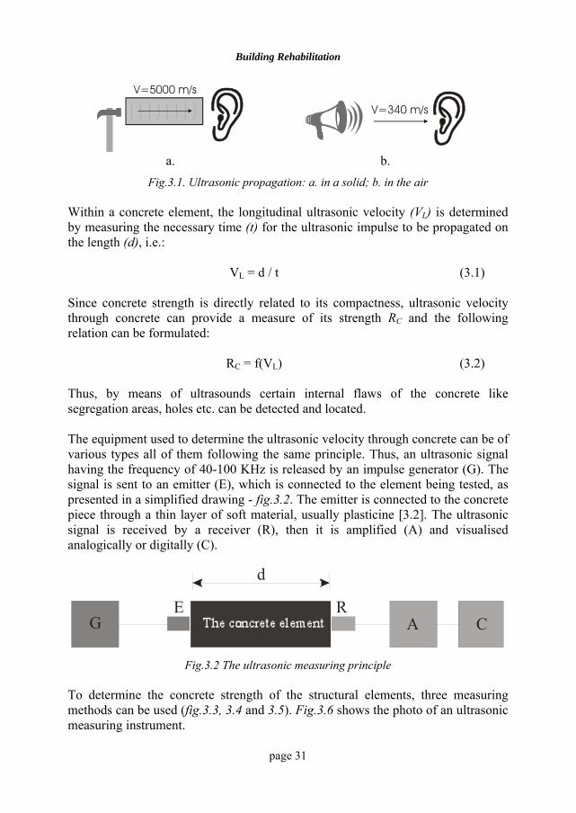
• destructive methods. Experimental tests to establish the behaviour of the structural elements and the building are carried out “in situ”. Usually, the condition of the building is determined by dynamic measurements, which enable the identification of the structural model and the pre-and post-rehabilitation diagnosis. 3.2 ULTRASONIC DIAGNOSIS Ultrasonic velocity in a completely compact solid (void free) is about 5000 m/s compared to the sound velocity in the air is about 340 m/s [3.1], [3.2], [3.3], fig.3.1. Within the solid, ultrasonic velocity depends on compactness. The greater the compactness, the closer the velocity will get to the value corresponding to a completely compact object and the greater the percentage of voids the lower the velocity.
Building Rehabilitation
page 31
V=5000 m/s
V=340 m/s
a. b.
Fig.3.1. Ultrasonic propagation: a. in a solid; b. in the air Within a concrete element, the longitudinal ultrasonic velocity (VL) is determined by measuring the necessary time (t) for the ultrasonic impulse to be propagated on the length (d), i.e.:
VL = d / t (3.1) Since concrete strength is directly related to its compactness, ultrasonic velocity through concrete can provide a measure of its strength RC and the following relation can be formulated:
RC = f(VL) (3.2) Thus, by means of ultrasounds certain internal flaws of the concrete like segregation areas, holes etc. can be detected and located. The equipment used to determine the ultrasonic velocity through concrete can be of various types all of them following the same principle. Thus, an ultrasonic signal having the frequency of 40-100 KHz is released by an impulse generator (G). The signal is sent to an emitter (E), which is connected to the element being tested, as presented in a simplified drawing - fig.3.2. The emitter is connected to the concrete piece through a thin layer of soft material, usually plasticine [3.2]. The ultrasonic signal is received by a receiver (R), then it is amplified (A) and visualised analogically or digitally (C).
GRE
A C
d
Fig.3.2 The ultrasonic measuring principle
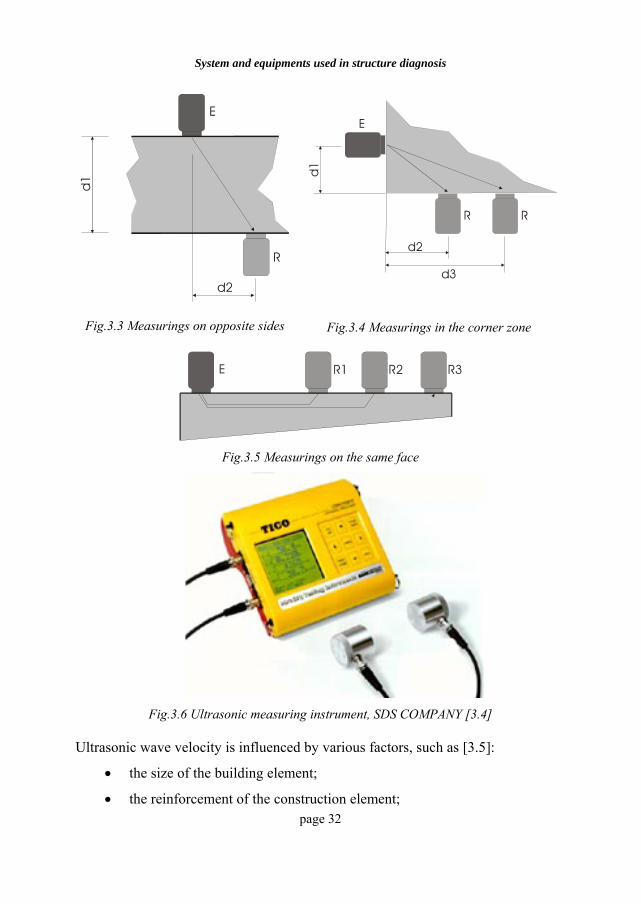
To determine the concrete strength of the structural elements, three measuring methods can be used (fig.3.3, 3.4 and 3.5). Fig.3.6 shows the photo of an ultrasonic measuring instrument.
System and equipments used in structure diagnosis
page 32
E
R
d1
d2
E
R R
d1
d2
d3
Fig.3.3 Measurings on opposite sides
Fig.3.4 Measurings in the corner zone
E R1 R2 R3
Fig.3.5 Measurings on the same face
Fig.3.6 Ultrasonic measuring instrument, SDS COMPANY [3.4]
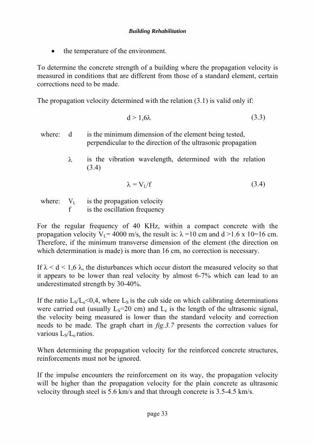
Ultrasonic wave velocity is influenced by various factors, such as [3.5]:
• the size of the building element;
• the reinforcement of the construction element;
Building Rehabilitation
page 33
• the temperature of the environment. To determine the concrete strength of a building where the propagation velocity is measured in conditions that are different from those of a standard element, certain corrections need to be made. The propagation velocity determined with the relation (3.1) is valid only if:
d > 1,6λ
(3.3)
where: d is the minimum dimension of the element being tested, perpendicular to the direction of the ultrasonic propagation
λ is the vibration wavelength, determined with the relation (3.4)
λ = VL/f (3.4)
where: VL is the propagation velocity f is the oscillation frequency
For the regular frequency of 40 KHz, within a compact concrete with the propagation velocity VL= 4000 m/s, the result is: λ =10 cm and d >1.6 x 10=16 cm. Therefore, if the minimum transverse dimension of the element (the direction on which determination is made) is more than 16 cm, no correction is necessary. If λ < d < 1,6 λ, the disturbances which occur distort the measured velocity so that it appears to be lower than real velocity by almost 6-7% which can lead to an underestimated strength by 30-40%. If the ratio LS/Le<0,4, where LS is the cub side on which calibrating determinations were carried out (usually LS=20 cm) and Le is the length of the ultrasonic signal, the velocity being measured is lower than the standard velocity and correction needs to be made. The graph chart in fig.3.7 presents the correction values for various LS/Le ratios. When determining the propagation velocity for the reinforced concrete structures, reinforcements must not be ignored. If the impulse encounters the reinforcement on its way, the propagation velocity will be higher than the propagation velocity for the plain concrete as ultrasonic velocity through steel is 5.6 km/s and that through concrete is 3.5-4.5 km/s.
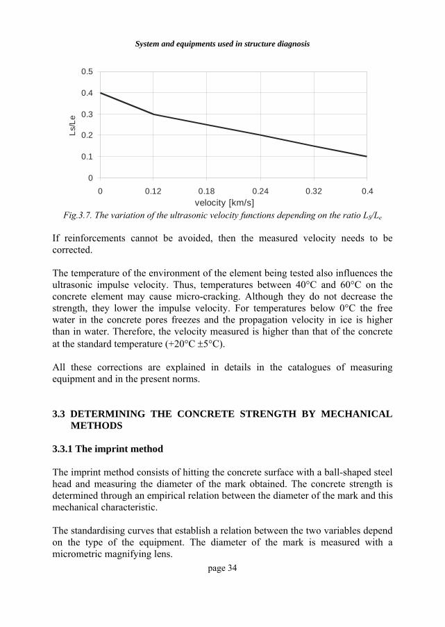
System and equipments used in structure diagnosis
page 34
0
0.1
0.2
0.3
0.4
0.5
0 0.12 0.18 0.24 0.32 0.4
variatia vitezei [Km/s]
Ls/L
e
velocity [km/s] Fig.3.7. The variation of the ultrasonic velocity functions depending on the ratio LS/Le
If reinforcements cannot be avoided, then the measured velocity needs to be corrected. The temperature of the environment of the element being tested also influences the ultrasonic impulse velocity. Thus, temperatures between 40°C and 60°C on the concrete element may cause micro-cracking. Although they do not decrease the strength, they lower the impulse velocity. For temperatures below 0°C the free water in the concrete pores freezes and the propagation velocity in ice is higher than in water. Therefore, the velocity measured is higher than that of the concrete at the standard temperature (+20°C ±5°C). All these corrections are explained in details in the catalogues of measuring equipment and in the present norms. 3.3 DETERMINING THE CONCRETE STRENGTH BY MECHANICAL
METHODS 3.3.1 The imprint method The imprint method consists of hitting the concrete surface with a ball-shaped steel head and measuring the diameter of the mark obtained. The concrete strength is determined through an empirical relation between the diameter of the mark and this mechanical characteristic. The standardising curves that establish a relation between the two variables depend on the type of the equipment. The diameter of the mark is measured with a micrometric magnifying lens.
Building Rehabilitation
page 35
3.3.2 The back pressure method
The back pressure method is based on the energy returned at the impact between two objects. Thus, the concrete strength can be determined by measuring the back pressure of a mobile system at its impact with a concrete surface. The instrument used for this test is called sclerometer. The concrete strength determination by means of the sclerometer is based on the relation between the concrete hardness expressed by the back pressure index and its compressive strength, using a concrete structure as standard element. The results of the sclerometer test are relevant for a concrete layer whose thickness is about 3 cm from the tested surface. The areas where strength is determined with the sclerometer must comply with the following conditions:
i. the surface being tested should not coincide with the concrete pouring direction or with its opposite side;
ii. the concrete in the testing region should be as representative as possible for the whole element from the point of view of homogeneity and quality;
iii. it should cover both the highly stressed areas and the potential low-strength regions;
iv. the concrete surface must be perfectly flat and smooth;
v. the surface of the tested area for which the concrete quality is determined must be of maximum 400 cm2 and minimum 100 cm2;
vi. number of tested points required for the determination of the concrete strength in a single area must correspond to at least 5 correct measurements;
vii. the tested points will be chosen so that the regions with gravel size of more than 7 mm and superficial visible holes would be avoided;
viii. the sclerometer must be kept perfectly perpendicular on the tested area;
ix. the surface must not be humid. To determine the strength of other types of concrete whose characteristics are different from those of the standard concrete, correction coefficients will be used [3.2], [3.3].
System and equipments used in structure diagnosis
page 36
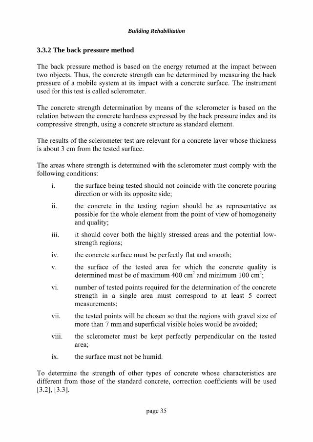
Fig.3.8 presents the photo of a sclerometer used to measure the concrete strength by means of the back pressure method.
Fig.3.8 The sclerometer Schmidt, SDS COMPANY [3.4]
3.4 DETERMINING THE CONCRETE STRENGTH BY DESTRUCTIVE
TESTS ON CORES/SAMPLES 3.4.1 Core extraction The place of core extraction from construction elements is established according to the damage level of the construction and its importance, taking care that:
• they should not cross reinforcements – the choice of these regions is based on the project or the non-destructive measurements with the pachometer;
• the extraction areas should be representative for the examined element;
• core extraction from locally deteriorated areas can be used only to point out the characteristics of the examined flaw – the cores obtained by this method cannot be used to determine the concrete strength of the examined element.
The core diameter d depends on the following factors:
• the maximum aggregate size for which the relation below is valid
dcore ≥ (3…4) dmax of the aggreg. (3.5)
Building Rehabilitation
page 37
• the distance between the reinforcements in the extraction areas (a) measured in centimetres for which the following condition should be observed:
dcore ≤ a-dreinforcement- 2dcore cutter-3 (3.6)
When extracting the core, the strength reserve and the stress level of the cross-section estimated by the expert need to be considered. The hole made by drilling will be filled with a suitable material to restore the load bearing capacity of the weakened section. The height of the core that is going to be tested destructively must comply with the following limits:
dcore≤ hcore≤ 2dcore (3.7) If the core ending surfaces are not the result of the plane and perpendicular cutting on generators, after the extraction, certain remedial works will need to be made by:
• polishing the end surface under water jet (for unevenness of maximum 2-3mm)
• cutting the end surface with a diamond tool under water jet
• filling the end surface with a putty (epoxy mortar, cement mortar, sulphur paste with or without smoke black) which complies with the following requirements:
- maximum thickness of 1 cm,
- good adherence to concrete,
- high hardening rate,
- its modulus of elasticity is close to or higher than that of the concrete in the core,
- its strength to compression is close to a higher than that of the core concrete.
3.4.2 The number of cores and their preserving conditions
The number of cores extracted for a structure will be chosen according to the following criteria:
i. the number of the examined elements;
ii. the stress pattern of the element;
System and equipments used in structure diagnosis
page 38
iii. local variations in the quality of concrete from one element to another and within the same element;
iv. the extent of the damage. When determining the necessary number of cores sufficient information needs to be gathered and taken into account. It is recommended that the test specimens should be kept in water at 20-25°C from their cutting to the test and at least 24 hours before the test, the cores must be taken out and kept in air at the same temperature for their conditioning.
3.4.3 Compression core testing The strength recorded by the testing machine is not the real concrete compressive strength due to the following factors:
• the degradation of a concrete layer adjacent to the lateral surface of the core due to core drilling;
• the degradation o a concrete layer adjacent to the end surfaces of the core;
• the existence of an interlayer between the machine loading plates and the core whose properties are different from those of the concrete;
• the ratio between the core height and its diameter. The strength under compression determined on cores must be corrected according to the following factors:
• the diameter of the core,
• the slenderness of the core measured through the ratio:
hcore/dcore
• the damaged ending layers,
• the device used to flatten the surfaces. The results of the tests are written down in an analysis bulletin which should include:
i. information about the structure;
ii. the indication of the element the core has been extracted from;
Building Rehabilitation
page 39
iii. the direction of the core extraction versus the direction of the concrete pouring;
iv. the core dimensions;
v. the end surface preparation;
vi. the nature of the evening layer used (if necessary);
vii. the number, diameter and orientation of the bars found in the core;
viii. the compressive strength measured directly on the core
ix. the values of the strength correction coefficients;
x. the strength values obtained for each test bar after correction;
xi. the class and the age of the tested concrete;
xii. the statistic processing of the test results;
xiii. the test conclusions. 3.4.4 Non-destructive testing of cores The non-destructive testing of cores is necessary to determine the elastic constants of the concrete and to verify or determine the relation between the parameters used in the non-destructive tests. The determination of the concrete elastic constants on cores is done by longitudinal resonance methods and ultrasonic methods. The dimensions of the test specimens used to determine the elasto-dynamic constants by the non-destructive resonance method must comply with the following condition (3.8):
hcore ≥ 4 dcore (3.8) and under unusual circumstances the following relation is accepted:
hcore ≥ 3dcore (3.9) When the longitudinal resonance methods are used, the test specimen is fixed at its middle length and the emitter and the receiver are disposed one at each end. The dynamic modulus of elasticity of concrete Ed is determined with the relation:
System and equipments used in structure diagnosis
page 40
La2
L2
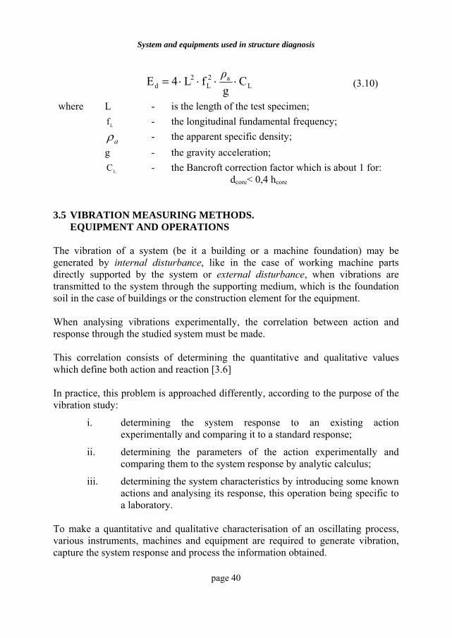
d Cg
fL4E ⋅⋅⋅⋅=ρ
(3.10)
where L - is the length of the test specimen;
Lf - the longitudinal fundamental frequency;
aρ - the apparent specific density; g - the gravity acceleration;
LC - the Bancroft correction factor which is about 1 for: dcore< 0,4 hcore
3.5 VIBRATION MEASURING METHODS.
EQUIPMENT AND OPERATIONS The vibration of a system (be it a building or a machine foundation) may be generated by internal disturbance, like in the case of working machine parts directly supported by the system or external disturbance, when vibrations are transmitted to the system through the supporting medium, which is the foundation soil in the case of buildings or the construction element for the equipment. When analysing vibrations experimentally, the correlation between action and response through the studied system must be made. This correlation consists of determining the quantitative and qualitative values which define both action and reaction [3.6] In practice, this problem is approached differently, according to the purpose of the vibration study:
i. determining the system response to an existing action experimentally and comparing it to a standard response;
ii. determining the parameters of the action experimentally and comparing them to the system response by analytic calculus;
iii. determining the system characteristics by introducing some known actions and analysing its response, this operation being specific to a laboratory.
To make a quantitative and qualitative characterisation of an oscillating process, various instruments, machines and equipment are required to generate vibration, capture the system response and process the information obtained.
Building Rehabilitation
page 41
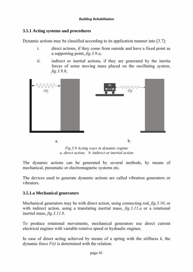
3.5.1 Acting systems and procedures Dynamic actions may be classified according to its application manner into [3.7]:
i. direct actions, if they come from outside and have a fixed point as a supporting point, fig.3.9.a;
ii. indirect or inertial actions, if they are generated by the inertia forces of some moving mass placed on the oscillating system, fig.3.9.b;
F(t)
F(t)
a. b.
Fig.3.9 Acting ways in dynamic regime a. direct action; b. indirect or inertial action
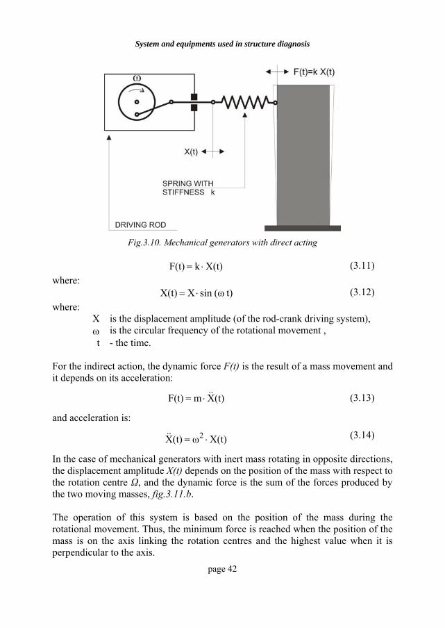
The dynamic actions can be generated by several methods, by means of mechanical, pneumatic or electromagnetic systems etc. The devices used to generate dynamic actions are called vibration generators or vibrators. 3.5.1.a Mechanical generators Mechanical generators may be with direct action, using connecting rod, fig.3.10, or with indirect action, using a translating inertial mass, fig.3.11.a or a rotational inertial mass, fig.3.11.b. To produce rotational movements, mechanical generators use direct current electrical engines with variable rotative speed or hydraulic engines. In case of direct acting achieved by means of a spring with the stiffness k, the dynamic force F(t) is determined with the relation:
System and equipments used in structure diagnosis
page 42
Fig.3.10. Mechanical generators with direct acting
X(t)kF(t) ⋅= (3.11)
where: t)(ωsin XX(t) ⋅= (3.12)
where: X is the displacement amplitude (of the rod-crank driving system), ω is the circular frequency of the rotational movement , t - the time.
For the indirect action, the dynamic force F(t) is the result of a mass movement and it depends on its acceleration:
(t)X mF(t) &&⋅= (3.13)
and acceleration is:
X(t)ω(t)X 2 ⋅=&& (3.14)
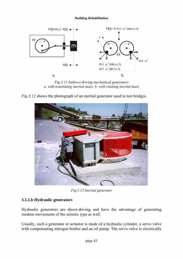
In the case of mechanical generators with inert mass rotating in opposite directions, the displacement amplitude X(t) depends on the position of the mass with respect to the rotation centre Ω, and the dynamic force is the sum of the forces produced by the two moving masses, fig.3.11.b. The operation of this system is based on the position of the mass during the rotational movement. Thus, the minimum force is reached when the position of the mass is on the axis linking the rotation centres and the highest value when it is perpendicular to the axis.
Building Rehabilitation
page 43
ω
X(t)
F(t)=m X(t)ω 2
ω
F(t)= 2 m r cos tω (ω )2
m r cos tω (ω )m r sin tω (ω )2
2m r ω 2
r
a. b.
Fig.3.11 Indirect-driving mechanical generators a. with translating inertial mass; b. with rotating inertial mass
Fig.3.12 shows the photograph of an inertial generator used to test bridges.
Fig.3.12 Inertial generator
3.5.1.b Hydraulic generators Hydraulic generators are direct-driving and have the advantage of generating random movements of the seismic type as well. Usually, such a generator or actuator is made of a hydraulic cylinder, a servo valve with compensating nitrogen bottles and an oil pump. The servo valve is electrically
System and equipments used in structure diagnosis
page 44
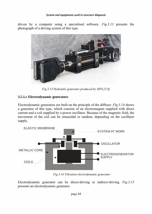
driven by a computer using a specialised software. Fig.3.13 presents the photograph of a driving system of this type.
Fig.3.13 Hydraulic generator produced by MTS [3.8]
3.5.1.c Electrodynamic generators Electrodynamic generators are built on the principle of the diffuser. Fig.3.14 shows a generator of this type, which consists of an electromagnet supplied with direct current and a coil supplied by a power oscillator. Because of the magnetic field, the movement of the coil can be sinusoidal or random, depending on the oscillator supply.
COILS
ELASTIC MEMBRANE
METALLIC CORE
OSCILLATOR
ELECTROGENERATORSUPPLY
SYSTEM AT WORK
Fig.3.14 Vibration electrodynamic generator
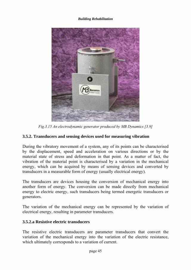
Electrodynamic generator can be direct-driving or indirect-driving. Fig.3.15 presents an electrodynamic generator.
Building Rehabilitation
page 45
Fig.3.15 An electrodynamic generator produced by MB Dynamics [3.9]
3.5.2. Transducers and sensing devices used for measuring vibration During the vibratory movement of a system, any of its points can be characterised by the displacement, speed and acceleration on various directions or by the material state of stress and deformation in that point. As a matter of fact, the vibration of the material point is characterised by a variation in the mechanical energy, which can be acquired by means of sensing devices and converted by transducers in a measurable form of energy (usually electrical energy). The transducers are devices housing the conversion of mechanical energy into another form of energy. The conversion can be made directly from mechanical energy to electric energy, such transducers being termed energetic transducers or generators. The variation of the mechanical energy can be represented by the variation of electrical energy, resulting in parameter transducers. 3.5.2.a Resistive electric transducers The resistive electric transducers are parameter transducers that convert the variation of the mechanical energy into the variation of the electric resistance, which ultimately corresponds to a variation of current.
System and equipments used in structure diagnosis
page 46
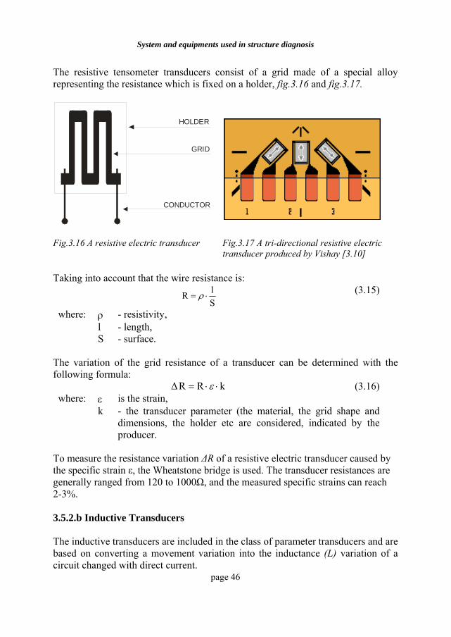
The resistive tensometer transducers consist of a grid made of a special alloy representing the resistance which is fixed on a holder, fig.3.16 and fig.3.17.
HOLDER
GRID
CONDUCTOR
Fig.3.16 A resistive electric transducer
Fig.3.17 A tri-directional resistive electric transducer produced by Vishay [3.10]
Taking into account that the wire resistance is:
SlR ⋅= ρ (3.15)
where: ρ - resistivity, l - length, S - surface.
The variation of the grid resistance of a transducer can be determined with the following formula:
kRR∆ ⋅⋅= ε (3.16) where: ε is the strain, k - the transducer parameter (the material, the grid shape and
dimensions, the holder etc are considered, indicated by the producer.
To measure the resistance variation ∆R of a resistive electric transducer caused by the specific strain ε, the Wheatstone bridge is used. The transducer resistances are generally ranged from 120 to 1000Ω, and the measured specific strains can reach 2-3%. 3.5.2.b Inductive Transducers The inductive transducers are included in the class of parameter transducers and are based on converting a movement variation into the inductance (L) variation of a circuit changed with direct current.
Building Rehabilitation
page 47
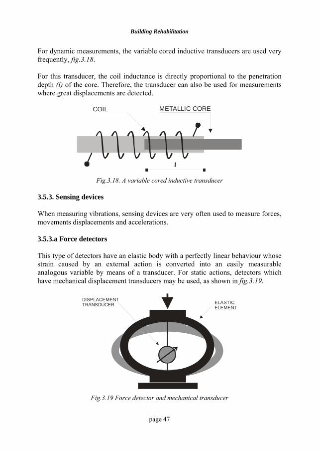
For dynamic measurements, the variable cored inductive transducers are used very frequently, fig.3.18. For this transducer, the coil inductance is directly proportional to the penetration depth (l) of the core. Therefore, the transducer can also be used for measurements where great displacements are detected.
METALLIC CORECOIL
l
Fig.3.18. A variable cored inductive transducer
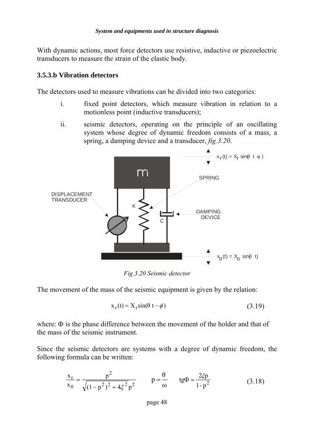
3.5.3. Sensing devices When measuring vibrations, sensing devices are very often used to measure forces, movements displacements and accelerations. 3.5.3.a Force detectors This type of detectors have an elastic body with a perfectly linear behaviour whose strain caused by an external action is converted into an easily measurable analogous variable by means of a transducer. For static actions, detectors which have mechanical displacement transducers may be used, as shown in fig.3.19.
ELASTICELEMENT
DISPLACEMENTTRANSDUCER
Fig.3.19 Force detector and mechanical transducer
System and equipments used in structure diagnosis
page 48
With dynamic actions, most force detectors use resistive, inductive or piezoelectric transducers to measure the strain of the elastic body. 3.5.3.b Vibration detectors The detectors used to measure vibrations can be divided into two categories:
i. fixed point detectors, which measure vibration in relation to a motionless point (inductive transducers);
ii. seismic detectors, operating on the principle of an oscillating system whose degree of dynamic freedom consists of a mass, a spring, a damping device and a transducer, fig.3.20.
SPRING
DISPLACEMENTTRANSDUCER
DAMPINGDEVICE
K
C
x (t) = X sin( t)θ
x (t) = X sin( t - )θ φr r
o o
Fig.3.20 Seismic detector
The movement of the mass of the seismic equipment is given by the relation:
)tsin(X(t)x rr φ−= θ (3.19) where: Φ is the phase difference between the movement of the holder and that of the mass of the seismic instrument. Since the seismic detectors are systems with a degree of dynamic freedom, the following formula can be written:
2222
2
0
r
p4)p(1
pxx
ξ+−=
ωθp = 2p-1
p2tg ξ=Φ (3.18)
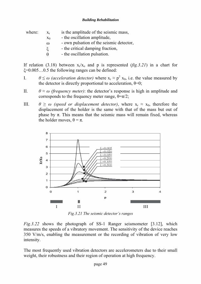
Building Rehabilitation
page 49
where: xr is the amplitude of the seismic mass, x0 - the oscillation amplitude, ω - own pulsation of the seismic detector, ξ - the critical damping fraction, θ - the oscillation pulsation.
If relation (3.18) between xr/xo and p is represented (fig.3.21) in a chart for ξ=0.005…0.5 the following ranges can be defined:
I. θ ≤ ω (acceleration detector) where xr ≈ p2 x0, i.e. the value measured by the detector is directly proportional to acceleration, θ=0;
II. θ ≈ ω (frequency meter): the detector’s response is high in amplitude and corresponds to the frequency meter range, θ=π/2;
III. θ ≥ ω (speed or displacement detector), where xr ≈ x0, therefore the displacement of the holder is the same with that of the mass but out of phase by π. This means that the seismic mass will remain fixed, whereas the holder moves, θ = π.
Fig.3.21 The seismic detector’s ranges Fig.3.22 shows the photograph of SS-1 Ranger seismometer [3.12], which measures the speeds of a vibratory movement. The sensitivity of the device reaches 350 V/m/s, enabling the measurement or the recording of vibration of very low intensity. The most frequently used vibration detectors are accelerometers due to their small weight, their robustness and their region of operation at high frequency.
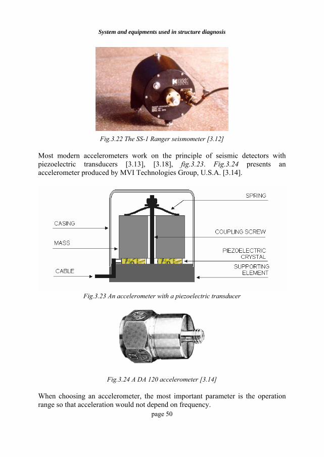
System and equipments used in structure diagnosis
page 50
Fig.3.22 The SS-1 Ranger seismometer [3.12]
Most modern accelerometers work on the principle of seismic detectors with piezoelectric transducers [3.13], [3.18], fig.3.23. Fig.3.24 presents an accelerometer produced by MVI Technologies Group, U.S.A. [3.14].
Fig.3.23 An accelerometer with a piezoelectric transducer
Fig.3.24 A DA 120 accelerometer [3.14]
When choosing an accelerometer, the most important parameter is the operation range so that acceleration would not depend on frequency.
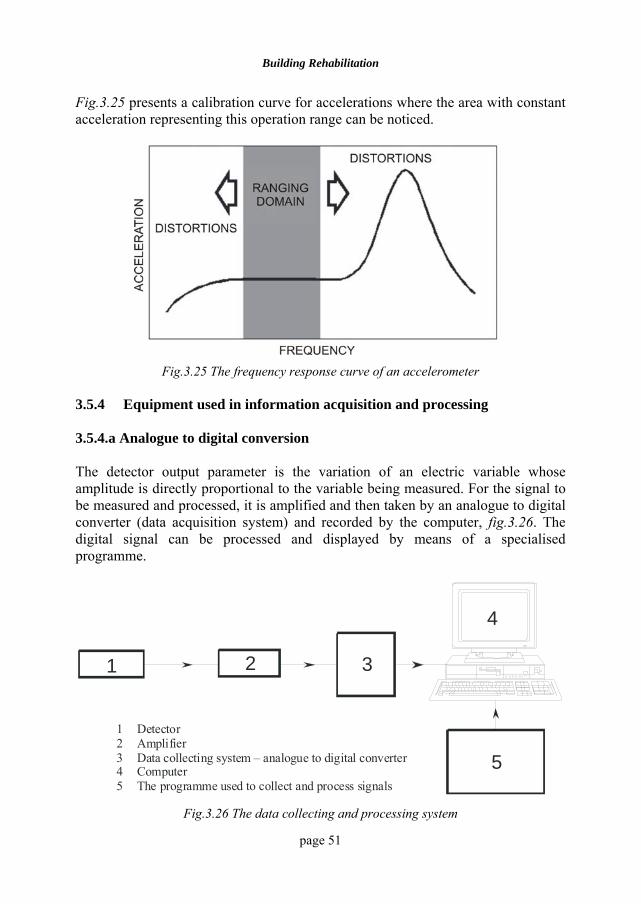
Building Rehabilitation
page 51
Fig.3.25 presents a calibration curve for accelerations where the area with constant acceleration representing this operation range can be noticed.
Fig.3.25 The frequency response curve of an accelerometer
3.5.4 Equipment used in information acquisition and processing 3.5.4.a Analogue to digital conversion The detector output parameter is the variation of an electric variable whose amplitude is directly proportional to the variable being measured. For the signal to be measured and processed, it is amplified and then taken by an analogue to digital converter (data acquisition system) and recorded by the computer, fig.3.26. The digital signal can be processed and displayed by means of a specialised programme.
1 2 3
4
5
1 Detector2 Amplifier3 Data collecting system – analogue to digital converter4 Computer5 The programme used to collect and process signals
Fig.3.26 The data collecting and processing system
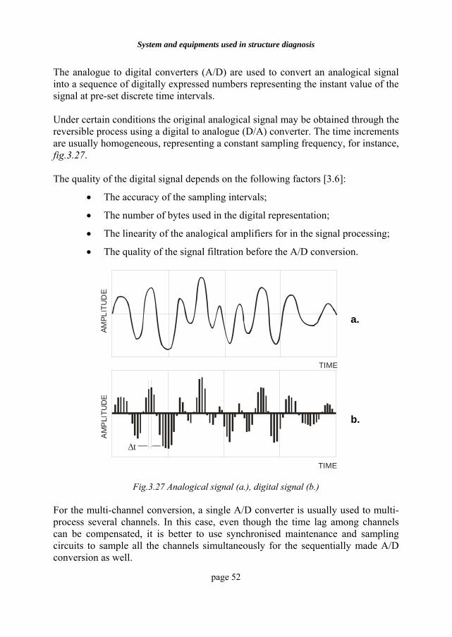
System and equipments used in structure diagnosis
page 52
The analogue to digital converters (A/D) are used to convert an analogical signal into a sequence of digitally expressed numbers representing the instant value of the signal at pre-set discrete time intervals. Under certain conditions the original analogical signal may be obtained through the reversible process using a digital to analogue (D/A) converter. The time increments are usually homogeneous, representing a constant sampling frequency, for instance, fig.3.27. The quality of the digital signal depends on the following factors [3.6]:
• The accuracy of the sampling intervals;
• The number of bytes used in the digital representation;
• The linearity of the analogical amplifiers for in the signal processing;
• The quality of the signal filtration before the A/D conversion.
TIME
AMPL
ITU
DE
a.
AM
PLI
TUD
E
∆t
TIME
b.
Fig.3.27 Analogical signal (a.), digital signal (b.)
For the multi-channel conversion, a single A/D converter is usually used to multi-process several channels. In this case, even though the time lag among channels can be compensated, it is better to use synchronised maintenance and sampling circuits to sample all the channels simultaneously for the sequentially made A/D conversion as well.
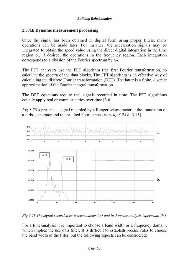
Building Rehabilitation
page 53
3.5.4.b Dynamic measurement processing Once the signal has been obtained in digital form using proper filters, many operations can be made later. For instance, the acceleration signals may be integrated to obtain the speed value using the direct digital integration in the time region or, if desired, the operations in the frequency region. Each integration corresponds to a division of the Fourier spectrum by jω. The FFT analysers use the FFT algorithm (the first Fourier transformation) to calculate the spectra of the data blocks, The FFT algorithm is an effective way of calculating the discrete Fourier transformation (DFT). The latter is a finite, discrete approximation of the Fourier integral transformation. The DFT equations require real signals recorded in time. The FFT algorithms equally apply real or complex series over time [3.6]. Fig.3.28.a presents a signal recorded by a Ranger seismometer at the foundation of a turbo generator and the resulted Fourier spectrum, fig.3.28.b [3.15].
0 1 2 3 4 5 6 7 8 9-0.02
-0.01
0.00
0.01
a.
0 10 20 30 40 50 600.0000
0.0002
0.0004
0.0006
0.0008
0.0010
6.3312.40
b.
Fig.3.28 The signal recorded by a seismometer (a.) and its Fourier analysis (spectrum) (b.) For a time-analysis it is important to choose a band width or a frequency domain, which implies the use of a filter. It is difficult to establish precise rules to choose the band width of the filter, but the following aspects can be considered:
System and equipments used in structure diagnosis
page 54
• for the stationary signals, particularly for the periodical signals containing discrete and equally spaced frequency components, it is recommended to use a constant band width on a linear frequency scale – the band width must be between one fifth and one third of the minimum domain of frequency analysed;
• for the stationary or transitory random signals, the spectrum shape will be determined by means of resonances so that the band width would be chosen of about one third of the band width of the narrowest resonance peak.
Usually, to represent a spectrum, a linear range of frequency is used together with a constant band width. In order to cover a large region of frequency, a frequency logarithmic scale may be selected. BIBLIOGRAPHY
3.1 Winden N.G.B., Ultrasonic measurement for setting control of concrete. Testing during concrete construction, Ed. by H.W. Reinhardt, Chapman & Hall, London, 1990.
3.2 Stefanescu-Goangă A., Determinarea rezistenţei betonului prin metode nedistructive, Exemple de calcul, Editura tehnică, Bucureşti, 1981.
3.3 Tertea I., Oneţ T.,Verificarea calităţii construcţiilor de beton armat şi beton precomprimat, Editura Dacia, Cluj-Napoca, 1979.
3.4 SDS COMPANY (www.concretendt.com/). 3.5 Pohl E., Prüfung von Beton mit Ultraschall, Deutsche Bauinformation,
Berlin, 1966. 3.6 Cyril, M. H., Shoc and Vibration Handbook, Fourth Edition, McGRAW-
HILL, 1995. 3.7 Ciongradi I., Ionescu C., Budescu M., Strat L., Atanasiu G., Stefan D.,
Severin C., Dinamica construcţiilor, lucrari de laborator, U.T. „Gh. Asachi” Iaşi, 1989.
3.8 MTS (www.mts.com). 3.9 MB Dynamics innovates and delivers SOLUTIONS, Vibration and
Shock (www.mbdynamics.com/). 3.10 Measurements Group (www.measurementsgroup.com/mg.htm) 3.11 KISTLER (www.kistler.com/tech_theory.htm). 3.12 SEISMOMETRUL SS-1, Ranger Seismometer, KINEMETRICS, USA. 3.13 Patrick L. W, Dynamic Force, Pressure, & Acceleration Measurement
(www.endevco.com/pdf_pat_articles/patw_dynamicforce-2.pdf).

Building Rehabilitation
page 55
3.14 10dB-STEEL (www.01db.com/GB/HTM/OVERFRM.HTM). 3.15 Ciongradi, I., Budescu, M., Albu, Gh., Analiza caracteristicilor dinamice
de la CET Craiova, UT Iaşi, 1998. 3.18 Buzdugan, Gh., Fetcu, L. şi Radeş, M., Vibraţii mecanice, Bucureşti,
Editura Didactică şi Pedagogică, 1982.
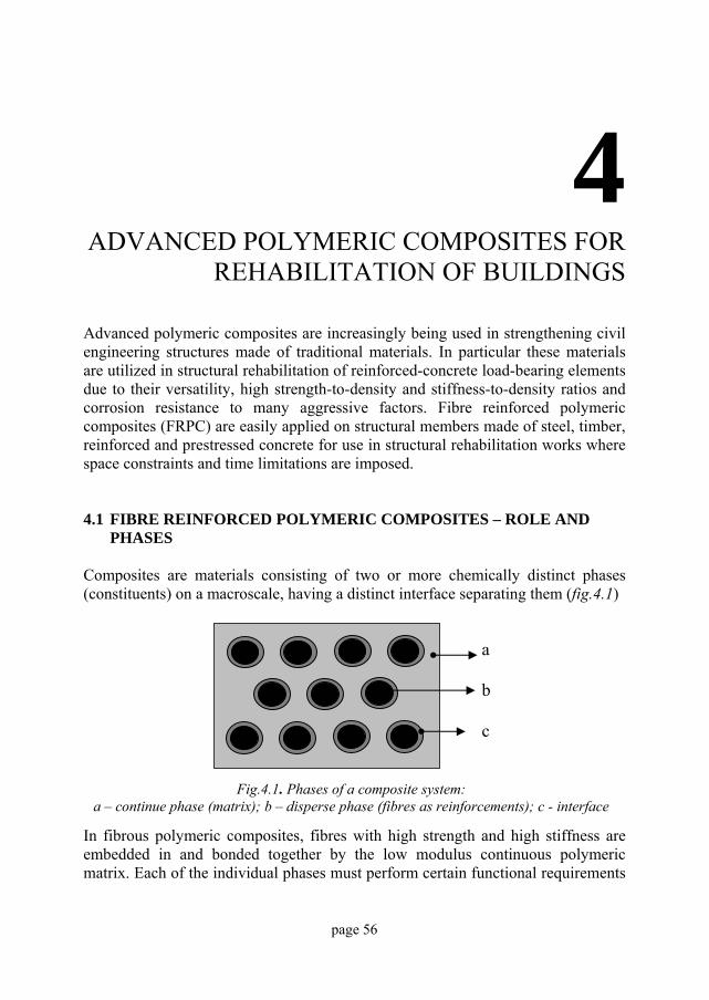
page 56
4 ADVANCED POLYMERIC COMPOSITES FOR
REHABILITATION OF BUILDINGS Advanced polymeric composites are increasingly being used in strengthening civil engineering structures made of traditional materials. In particular these materials are utilized in structural rehabilitation of reinforced-concrete load-bearing elements due to their versatility, high strength-to-density and stiffness-to-density ratios and corrosion resistance to many aggressive factors. Fibre reinforced polymeric composites (FRPC) are easily applied on structural members made of steel, timber, reinforced and prestressed concrete for use in structural rehabilitation works where space constraints and time limitations are imposed. 4.1 FIBRE REINFORCED POLYMERIC COMPOSITES – ROLE AND
PHASES Composites are materials consisting of two or more chemically distinct phases (constituents) on a macroscale, having a distinct interface separating them (fig.4.1)
In fibrous polymeric composites, fibres with high strength and high stiffness are embedded in and bonded together by the low modulus continuous polymeric matrix. Each of the individual phases must perform certain functional requirements
Fig.4.1. Phases of a composite system:
a – continue phase (matrix); b – disperse phase (fibres as reinforcements); c - interface
a b c
Building Rehabilitation
page 57
based on their mechanical properties so that a system containing them may perform satisfactorily as a composite [4.1]. In the case of advanced FRPC the continuous fibres constitute the backbone of the material and they determine its strength and stiffness in the direction of fibres. The desirable functional requirements of the fibres in a composite are: they should have a high elastic modulus for an efficient use of reinforcement; the fibres should have a high ultimate strength; the variation of strength between individual fibres should be low; the fibres must be stable and retain their strength during handling and fabrication; the diameter and surface of the fibres should be uniform. The polymeric matrix is required to fulfil the following main functions: to bind together the fibres and protect their surfaces from damage during handling, fabrication and service life of the composite; to disperse the fibres and separate them; to transfer stresses to the fibres; to be chemically and thermally compatible with fibres. The interface region is small but it has an important role in controlling the overall stress-strain behaviour of the composites. It exhibits a gradation of properties and it is a dominant factor in the resistance of the composite to corrosive environments. It also has a decisive role in the failure mechanisms and fracture toughness of the polymeric composites. 4.2. FIBRES FOR POLYMERIC COMPOSITES Reinforcing fibres for polymeric composites are fabricated from materials that are stronger and stiffer in the fibrous form than as a bulk material. Their high fibre aspect ratio (length/diameter) enables an effective transfer of load via matrix materials [4.2]. Proper selection of type, amount and orientation fibres results in a composite with desired mechanical characteristics such as axial strengths, elastic moduli, fatigue strength and cost. Fibres used in tension elements utilized for structural rehabilitation must meet certain requirements such as: high strength, high stiffness, convenient elongation at tensile fracture, high toughness, durability, low cost and availability in suitable forms. The diameter of fibres should be small enough to reduce the possibility of surface flows and to provide a high transfer area of shear stresses between the reinforcing fibres and the matrix.
Advanced polymeric composites for rehabilitation of buildings
page 58
The type and chemical compositions of fibres determine several properties such as: stress-strain relationship, toughness, durability and fatigue resistance. There are three main types of reinforcing fibres utilized in polymeric composites for structural rehabilitation of civil engineering structures: glass fibres, carbon and graphite fibres and aramid fibres. Fibres are available in a variety of configurations, which may be classified in the following main categories:
- unidirectional, in which all the fibres lie in one direction;
- bi-directional, where the fibres lie at 900 to one another;
- random, when the fibres are in-plane randomly distributed. A short description of the main types of fibres for polymeric composites used in structural rehabilitation is given below. 4.2.1. Glass fibres Glass fibres are the most commonly used reinforcing fibres for polymeric matrix composites. Molten glass can be drawn into continuous filaments that are bundled into rovings. These rovings can be fabricated into chopped fibres, continuous strands, chopped strands mats and woven fabrics before using them as reinforcement in composites. During fabrication, fibre surfaces are coated to improve wetting by the matrix and provide better adhesion between the composite constituents. Coating the glass fibres with a coupling agent will provide a flexible layer at the interface, the strength of the bond is improved and the number of voids in the material is reduced [4.3]. The most common glass fibres are made of E-glass and S-glass. E-glass is the least expensive of all glass types and it has a wide application in fibre reinforced plastic industry. S-glass has higher tensile strength and higher modulus than E-glass. However, the higher cost of S-glass fibres makes them less popular than E-glass. The main properties of E-glass and S-glass are summarized in Table 4.1, which also gives the main properties of carbon and aramid fibres [4.4]. To facilitate fabrication of glass fibre reinforced polymers glass strands are incorporated into rovings, fabrics, woven rovings and mats.
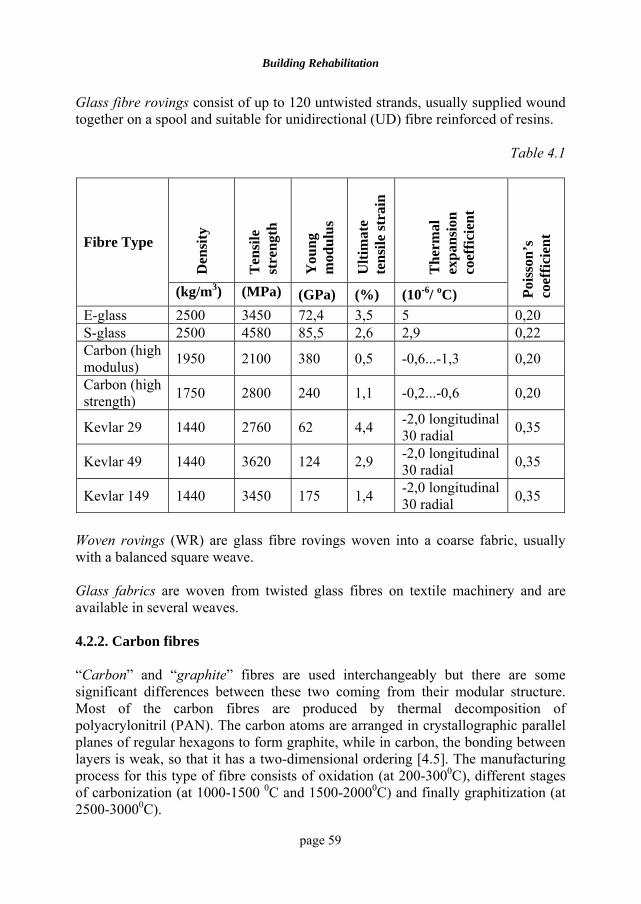
Building Rehabilitation
page 59
Glass fibre rovings consist of up to 120 untwisted strands, usually supplied wound together on a spool and suitable for unidirectional (UD) fibre reinforced of resins.
Table 4.1
Den
sity
Ten
sile
st
reng
th
You
ng
mod
ulus
Ulti
mat
e te
nsile
stra
in
The
rmal
ex
pans
ion
coef
ficie
nt
Fibre Type
(kg/m3) (MPa) (GPa) (%) (10-6/ oC) Pois
son’
s co
effic
ient
E-glass 2500 3450 72,4 3,5 5 0,20 S-glass 2500 4580 85,5 2,6 2,9 0,22 Carbon (high modulus) 1950 2100 380 0,5 -0,6...-1,3 0,20
Carbon (high strength) 1750 2800 240 1,1 -0,2...-0,6 0,20
Kevlar 29 1440 2760 62 4,4 -2,0 longitudinal 30 radial 0,35
Kevlar 49 1440 3620 124 2,9 -2,0 longitudinal 30 radial 0,35
Kevlar 149 1440 3450 175 1,4 -2,0 longitudinal 30 radial 0,35
Woven rovings (WR) are glass fibre rovings woven into a coarse fabric, usually with a balanced square weave. Glass fabrics are woven from twisted glass fibres on textile machinery and are available in several weaves. 4.2.2. Carbon fibres “Carbon” and “graphite” fibres are used interchangeably but there are some significant differences between these two coming from their modular structure. Most of the carbon fibres are produced by thermal decomposition of polyacrylonitril (PAN). The carbon atoms are arranged in crystallographic parallel planes of regular hexagons to form graphite, while in carbon, the bonding between layers is weak, so that it has a two-dimensional ordering [4.5]. The manufacturing process for this type of fibre consists of oxidation (at 200-3000C), different stages of carbonization (at 1000-1500 0C and 1500-20000C) and finally graphitization (at 2500-30000C).
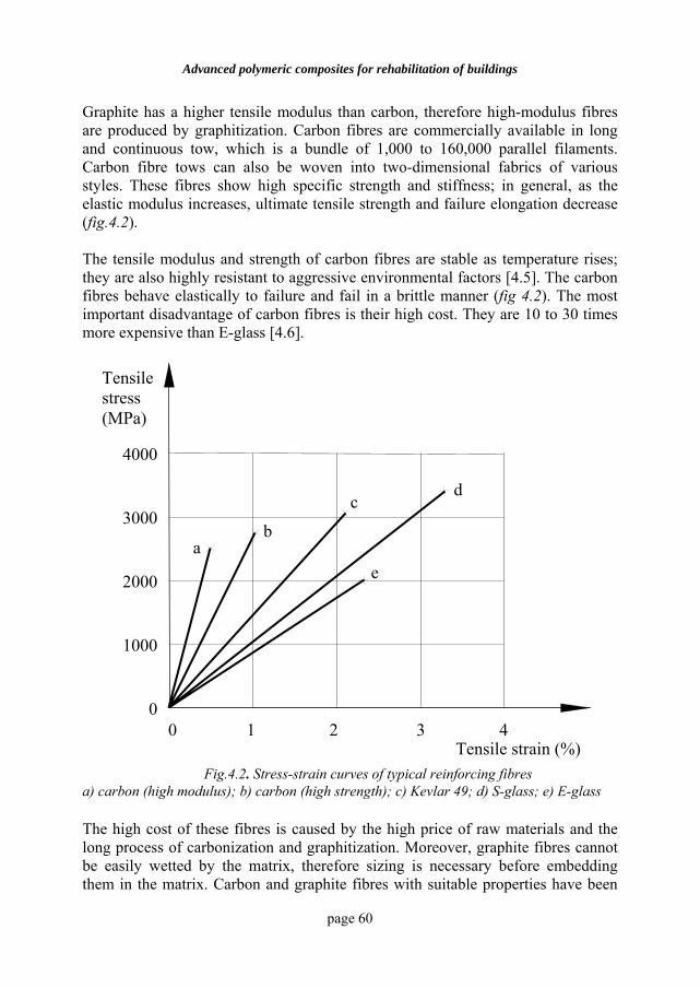
Advanced polymeric composites for rehabilitation of buildings
page 60
Graphite has a higher tensile modulus than carbon, therefore high-modulus fibres are produced by graphitization. Carbon fibres are commercially available in long and continuous tow, which is a bundle of 1,000 to 160,000 parallel filaments. Carbon fibre tows can also be woven into two-dimensional fabrics of various styles. These fibres show high specific strength and stiffness; in general, as the elastic modulus increases, ultimate tensile strength and failure elongation decrease (fig.4.2). The tensile modulus and strength of carbon fibres are stable as temperature rises; they are also highly resistant to aggressive environmental factors [4.5]. The carbon fibres behave elastically to failure and fail in a brittle manner (fig 4.2). The most important disadvantage of carbon fibres is their high cost. They are 10 to 30 times more expensive than E-glass [4.6].
a) carbon (high modulus); b) carbon (high strength); c) Kevlar 49; d) S-glass; e) E-glass The high cost of these fibres is caused by the high price of raw materials and the long process of carbonization and graphitization. Moreover, graphite fibres cannot be easily wetted by the matrix, therefore sizing is necessary before embedding them in the matrix. Carbon and graphite fibres with suitable properties have been
0 1 2 3 4
4000
3000
2000
1000
0
a b
c d
e
Tensile strain (%)
Tensile stress (MPa)
Fig.4.2. Stress-strain curves of typical reinforcing fibres
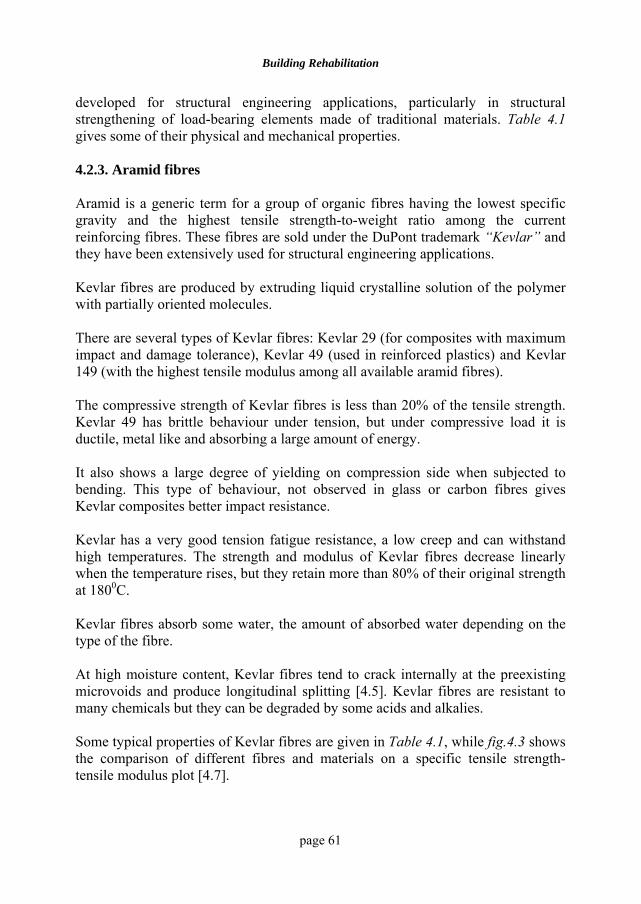
Building Rehabilitation
page 61
developed for structural engineering applications, particularly in structural strengthening of load-bearing elements made of traditional materials. Table 4.1 gives some of their physical and mechanical properties. 4.2.3. Aramid fibres Aramid is a generic term for a group of organic fibres having the lowest specific gravity and the highest tensile strength-to-weight ratio among the current reinforcing fibres. These fibres are sold under the DuPont trademark “Kevlar” and they have been extensively used for structural engineering applications. Kevlar fibres are produced by extruding liquid crystalline solution of the polymer with partially oriented molecules. There are several types of Kevlar fibres: Kevlar 29 (for composites with maximum impact and damage tolerance), Kevlar 49 (used in reinforced plastics) and Kevlar 149 (with the highest tensile modulus among all available aramid fibres). The compressive strength of Kevlar fibres is less than 20% of the tensile strength. Kevlar 49 has brittle behaviour under tension, but under compressive load it is ductile, metal like and absorbing a large amount of energy. It also shows a large degree of yielding on compression side when subjected to bending. This type of behaviour, not observed in glass or carbon fibres gives Kevlar composites better impact resistance. Kevlar has a very good tension fatigue resistance, a low creep and can withstand high temperatures. The strength and modulus of Kevlar fibres decrease linearly when the temperature rises, but they retain more than 80% of their original strength at 1800C. Kevlar fibres absorb some water, the amount of absorbed water depending on the type of the fibre. At high moisture content, Kevlar fibres tend to crack internally at the preexisting microvoids and produce longitudinal splitting [4.5]. Kevlar fibres are resistant to many chemicals but they can be degraded by some acids and alkalies. Some typical properties of Kevlar fibres are given in Table 4.1, while fig.4.3 shows the comparison of different fibres and materials on a specific tensile strength-tensile modulus plot [4.7].
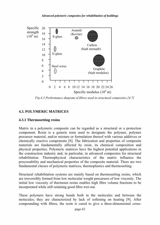
Advanced polymeric composites for rehabilitation of buildings
page 62
4.3. POLYMERIC MATRICES 4.3.1 Thermosetting resins Matrix in a polymeric composite can be regarded as a structural or a protection component. Resin is a generic term used to designate the polymer, polymer precursor material, and/or mixture or formulation thereof with various additives or chemically reactive components [8]. The fabrication and properties of composite materials are fundamentally affected by resin, its chemical composition and physical properties. Polymeric matrices have the highest potential applications in the construction industry and, in particular, in advanced composites for structural rehabilitation. Thermophysical characteristics of the matrix influence the processability and mechanical properties of the composite material. There are two fundamental classes of polymeric matrices, thermoplastics and thermosetting. Structural rehabilitation systems are mainly based on thermosetting resins, which are irreversibly formed from low molecular weight precursors of low viscosity. The initial low viscosity of thermoset resins enables high fibre volume fractions to be incorporated while still retaining good fibre wet-out. These polymers have strong bonds both in the molecules and between the molecules; they are characterized by lack of softening on heating [9]. After compounding with fibres, the resin is cured to give a three-dimensional cross-
Fig.4.3 Performance diagram of fibres used in structural composites [4.7]
E-glass
Steel wires Graphite
(high modulus)
Carbon (high strength)
Aramid (Kevlar)
S-glass
0 2 4 6 8 10 12 14 16 18 20 22 24 26
20 18 16 14 12 10 8 6 4 2 0
Specific modulus (106 m)
Specific strength (104 m)
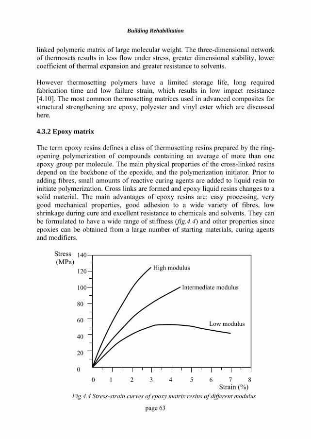
Building Rehabilitation
page 63
linked polymeric matrix of large molecular weight. The three-dimensional network of thermosets results in less flow under stress, greater dimensional stability, lower coefficient of thermal expansion and greater resistance to solvents. However thermosetting polymers have a limited storage life, long required fabrication time and low failure strain, which results in low impact resistance [4.10]. The most common thermosetting matrices used in advanced composites for structural strengthening are epoxy, polyester and vinyl ester which are discussed here.
4.3.2 Epoxy matrix The term epoxy resins defines a class of thermosetting resins prepared by the ring-opening polymerization of compounds containing an average of more than one epoxy group per molecule. The main physical properties of the cross-linked resins depend on the backbone of the epoxide, and the polymerization initiator. Prior to adding fibres, small amounts of reactive curing agents are added to liquid resin to initiate polymerization. Cross links are formed and epoxy liquid resins changes to a solid material. The main advantages of epoxy resins are: easy processing, very good mechanical properties, good adhesion to a wide variety of fibres, low shrinkage during cure and excellent resistance to chemicals and solvents. They can be formulated to have a wide range of stiffness (fig.4.4) and other properties since epoxies can be obtained from a large number of starting materials, curing agents and modifiers.
0 1 2 3 4 5 6 7 8
Stress (MPa)
High modulus
Intermediate modulus
Low modulus
140
120
100
80
60
40
20
0
Strain (%) Fig.4.4 Stress-strain curves of epoxy matrix resins of different modulus
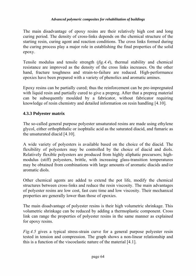
Advanced polymeric composites for rehabilitation of buildings
page 64
The main disadvantage of epoxy resins are their relatively high cost and long curing period. The density of cross-links depends on the chemical structure of the starting resin, curing agent and reaction conditions. The cross links formed during the curing process play a major role in establishing the final properties of the solid epoxy. Tensile modulus and tensile strength (fig.4.4), thermal stability and chemical resistance are improved as the density of the cross links increases. On the other hand, fracture toughness and strain-to-failure are reduced. High-performance epoxies have been prepared with a variety of phenolics and aromatic amines. Epoxy resins can be partially cured; thus the reinforcement can be pre-impregnated with liquid resin and partially cured to give a prepreg. After that a prepreg material can be subsequently moulded by a fabricator, without fabricator requiring knowledge of resin chemistry and detailed information on resin handling [4.10].
4.3.3 Polyester matrix The so-called general purpose polyester unsaturated resins are made using ethylene glycol, either orthophthalic or isophtalic acid as the saturated diacid, and fumaric as the unsaturated diacid [4.10]. A wide variety of polyesters is available based on the choice of the diacid. The flexibility of polyesters may be controlled by the choice of diacid and diols. Relatively flexible polyesters are produced from highly aliphatic precursors; high-modulus (stiff) polyesters, brittle, with increasing glass-transition temperatures may be obtained from combinations with large amounts of aromatic diacids and/or aromatic diols. Other chemical agents are added to extend the pot life, modify the chemical structures between cross-links and reduce the resin viscosity. The main advantages of polyester resins are low cost, fast cure time and low viscosity. Their mechanical properties are generally lower than those of epoxies. The main disadvantage of polyester resins is their high volumetric shrinkage. This volumetric shrinkage can be reduced by adding a thermoplastic component. Cross link can range the properties of polyester resins in the same manner as explained for epoxy resins. Fig.4.5 gives a typical stress-strain curve for a general purpose polyester resin tested in tension and compression. The graph shows a non-linear relationship and this is a function of the viscoelastic nature of the material [4.1].
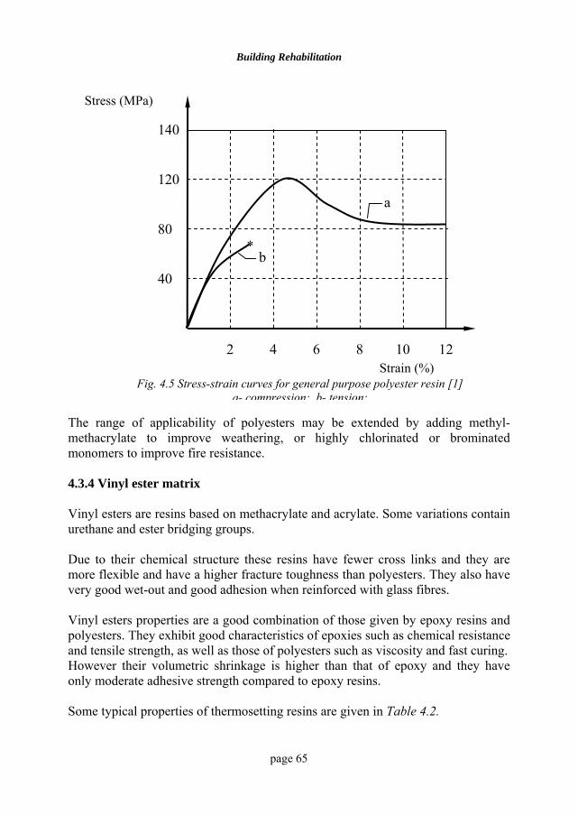
Building Rehabilitation
page 65
The range of applicability of polyesters may be extended by adding methyl-methacrylate to improve weathering, or highly chlorinated or brominated monomers to improve fire resistance. 4.3.4 Vinyl ester matrix Vinyl esters are resins based on methacrylate and acrylate. Some variations contain urethane and ester bridging groups. Due to their chemical structure these resins have fewer cross links and they are more flexible and have a higher fracture toughness than polyesters. They also have very good wet-out and good adhesion when reinforced with glass fibres. Vinyl esters properties are a good combination of those given by epoxy resins and polyesters. They exhibit good characteristics of epoxies such as chemical resistance and tensile strength, as well as those of polyesters such as viscosity and fast curing. However their volumetric shrinkage is higher than that of epoxy and they have only moderate adhesive strength compared to epoxy resins. Some typical properties of thermosetting resins are given in Table 4.2.
Strain (%)
a
b
140
120
80
40
2 4 6 8 10 12
*
Stress (MPa)
Fig. 4.5 Stress-strain curves for general purpose polyester resin [1] a- compression; b- tension;
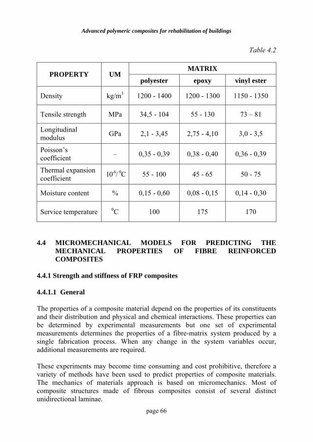
Advanced polymeric composites for rehabilitation of buildings
page 66
Table 4.2
MATRIX PROPERTY UM
polyester epoxy vinyl ester
Density kg/m3 1200 - 1400 1200 - 1300 1150 - 1350
Tensile strength MPa 34,5 - 104 55 - 130 73 – 81
Longitudinal modulus GPa 2,1 - 3,45 2,75 - 4,10 3,0 - 3,5
Poisson’s coefficient – 0,35 - 0,39 0,38 - 0,40 0,36 - 0,39
Thermal expansion coefficient 10-6/ 0C 55 - 100 45 - 65 50 - 75
Moisture content % 0,15 - 0,60 0,08 - 0,15 0,14 - 0,30
Service temperature 0C 100 175 170
4.4 MICROMECHANICAL MODELS FOR PREDICTING THE
MECHANICAL PROPERTIES OF FIBRE REINFORCED COMPOSITES
4.4.1 Strength and stiffness of FRP composites 4.4.1.1 General The properties of a composite material depend on the properties of its constituents and their distribution and physical and chemical interactions. These properties can be determined by experimental measurements but one set of experimental measurements determines the properties of a fibre-matrix system produced by a single fabrication process. When any change in the system variables occur, additional measurements are required. These experiments may become time consuming and cost prohibitive, therefore a variety of methods have been used to predict properties of composite materials. The mechanics of materials approach is based on micromechanics. Most of composite structures made of fibrous composites consist of several distinct unidirectional laminae.
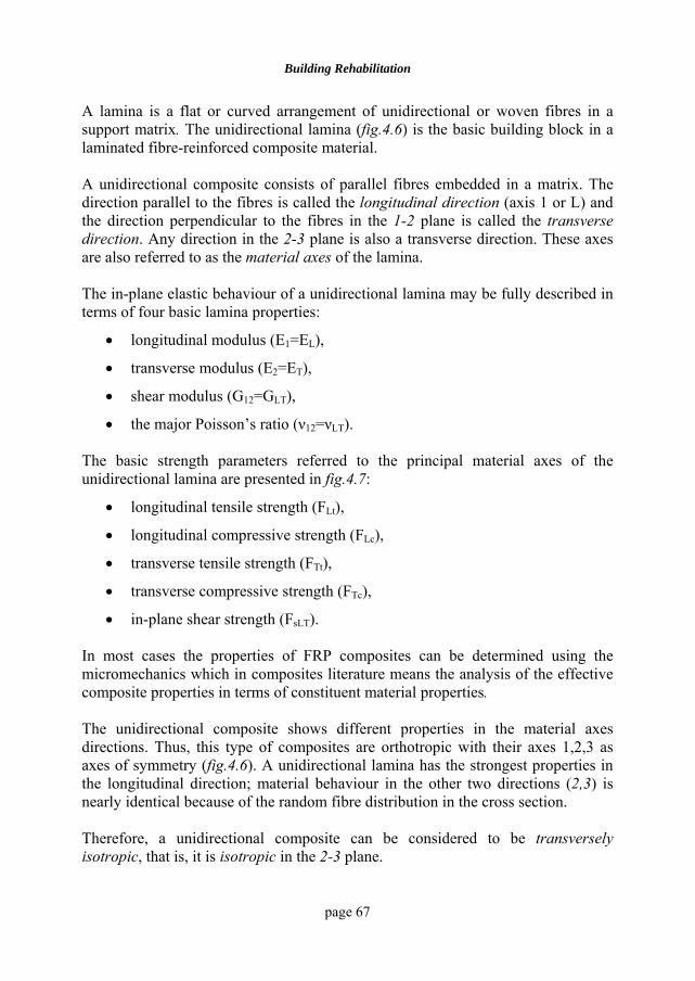
Building Rehabilitation
page 67
A lamina is a flat or curved arrangement of unidirectional or woven fibres in a support matrix. The unidirectional lamina (fig.4.6) is the basic building block in a laminated fibre-reinforced composite material. A unidirectional composite consists of parallel fibres embedded in a matrix. The direction parallel to the fibres is called the longitudinal direction (axis 1 or L) and the direction perpendicular to the fibres in the 1-2 plane is called the transverse direction. Any direction in the 2-3 plane is also a transverse direction. These axes are also referred to as the material axes of the lamina. The in-plane elastic behaviour of a unidirectional lamina may be fully described in terms of four basic lamina properties:
• longitudinal modulus (E1=EL),
• transverse modulus (E2=ET),
• shear modulus (G12=GLT),
• the major Poisson’s ratio (ν12=νLT). The basic strength parameters referred to the principal material axes of the unidirectional lamina are presented in fig.4.7:
• longitudinal tensile strength (FLt),
• longitudinal compressive strength (FLc),
• transverse tensile strength (FTt),
• transverse compressive strength (FTc),
• in-plane shear strength (FsLT). In most cases the properties of FRP composites can be determined using the micromechanics which in composites literature means the analysis of the effective composite properties in terms of constituent material properties. The unidirectional composite shows different properties in the material axes directions. Thus, this type of composites are orthotropic with their axes 1,2,3 as axes of symmetry (fig.4.6). A unidirectional lamina has the strongest properties in the longitudinal direction; material behaviour in the other two directions (2,3) is nearly identical because of the random fibre distribution in the cross section. Therefore, a unidirectional composite can be considered to be transversely isotropic, that is, it is isotropic in the 2-3 plane.
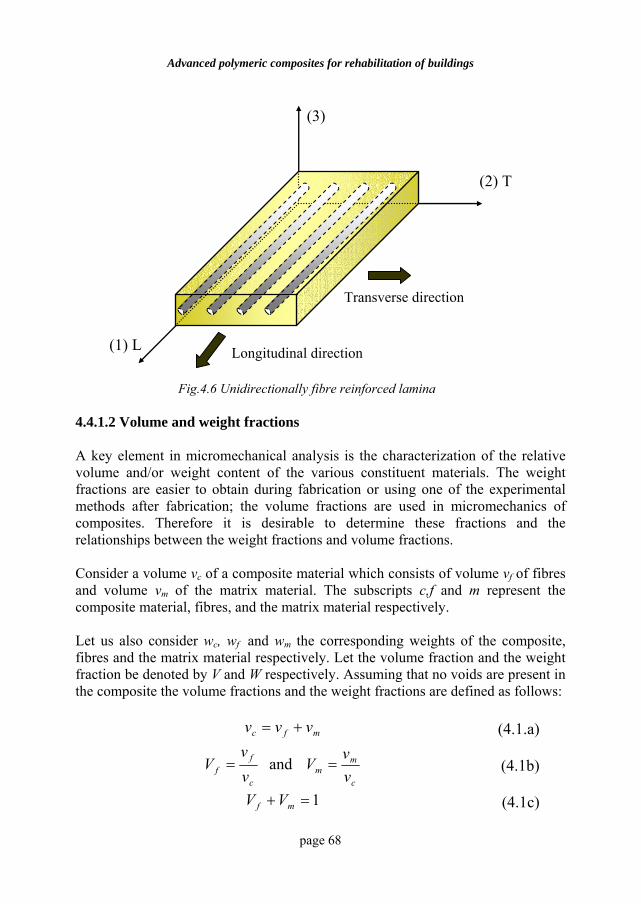
Advanced polymeric composites for rehabilitation of buildings
page 68
4.4.1.2 Volume and weight fractions A key element in micromechanical analysis is the characterization of the relative volume and/or weight content of the various constituent materials. The weight fractions are easier to obtain during fabrication or using one of the experimental methods after fabrication; the volume fractions are used in micromechanics of composites. Therefore it is desirable to determine these fractions and the relationships between the weight fractions and volume fractions. Consider a volume vc of a composite material which consists of volume vf of fibres and volume vm of the matrix material. The subscripts c,f and m represent the composite material, fibres, and the matrix material respectively. Let us also consider wc, wf and wm the corresponding weights of the composite, fibres and the matrix material respectively. Let the volume fraction and the weight fraction be denoted by V and W respectively. Assuming that no voids are present in the composite the volume fractions and the weight fractions are defined as follows:
mfc vvv += (4.1.a)
c
ff v
vV = and
c
mm v
vV = (4.1b)
1=+ mf VV (4.1c)
Fig.4.6 Unidirectionally fibre reinforced lamina
Transverse direction
Longitudinal direction
(3)
(2) T
(1) L
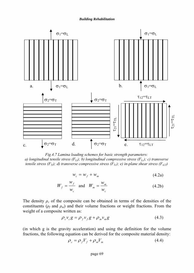
Building Rehabilitation
page 69
Fig.4.7 Lamina loading schemes for basic strength parameters: a) longitudinal tensile stress (FLt); b) longitudinal compressive stress (FLc); c) transverse tensile stress (FTt); d) transverse compressive stress (FTc); e) in-plane shear stress (FsLT)
mfc www += (4.2a)
c
ff w
wW = and
c
mm w
wW = (4.2b)
The density ρc of the composite can be obtained in terms of the densities of the constituents (ρf and ρm) and their volume fractions or weight fractions. From the weight of a composite written as:
gvgvgv mmffcc ρρρ += (4.3)
(in which g is the gravity acceleration) and using the definition for the volume fractions, the following equation can be derived for the composite material density:
mmffc VV ρρρ += (4.4)
a. b.
σ1=σL
σ1=σL
σ1=σL
σ1=σL
c. d. e.
σ2=σT
σ2=σT
σ2=σT
σ2=σT
τ12=τLT
τ12=τLT
τ 21=τ T
L
τ 21=τ T
L
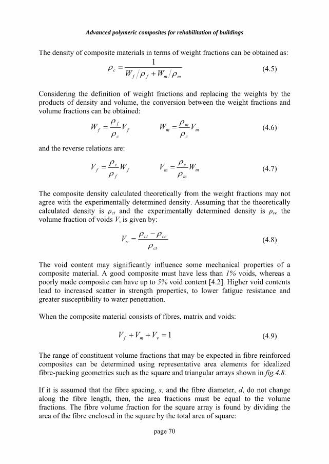
Advanced polymeric composites for rehabilitation of buildings
page 70
The density of composite materials in terms of weight fractions can be obtained as:
mmffc WW ρρ
ρ+
=1
(4.5)
Considering the definition of weight fractions and replacing the weights by the products of density and volume, the conversion between the weight fractions and volume fractions can be obtained:
mc
mmf
c
ff VWVW
ρρ
ρρ
== (4.6)
and the reverse relations are:
mm
cmf
f
cf WVWV
ρρ
ρρ
== (4.7)
The composite density calculated theoretically from the weight fractions may not agree with the experimentally determined density. Assuming that the theoretically calculated density is ρct and the experimentally determined density is ρce the volume fraction of voids Vv is given by:
ct
cectvV
ρρρ −
= (4.8)
The void content may significantly influence some mechanical properties of a composite material. A good composite must have less than 1% voids, whereas a poorly made composite can have up to 5% void content [4.2]. Higher void contents lead to increased scatter in strength properties, to lower fatigue resistance and greater susceptibility to water penetration. When the composite material consists of fibres, matrix and voids:
1=++ vmf VVV (4.9)
The range of constituent volume fractions that may be expected in fibre reinforced composites can be determined using representative area elements for idealized fibre-packing geometries such as the square and triangular arrays shown in fig.4.8. If it is assumed that the fibre spacing, s, and the fibre diameter, d, do not change along the fibre length, then, the area fractions must be equal to the volume fractions. The fibre volume fraction for the square array is found by dividing the area of the fibre enclosed in the square by the total area of square:
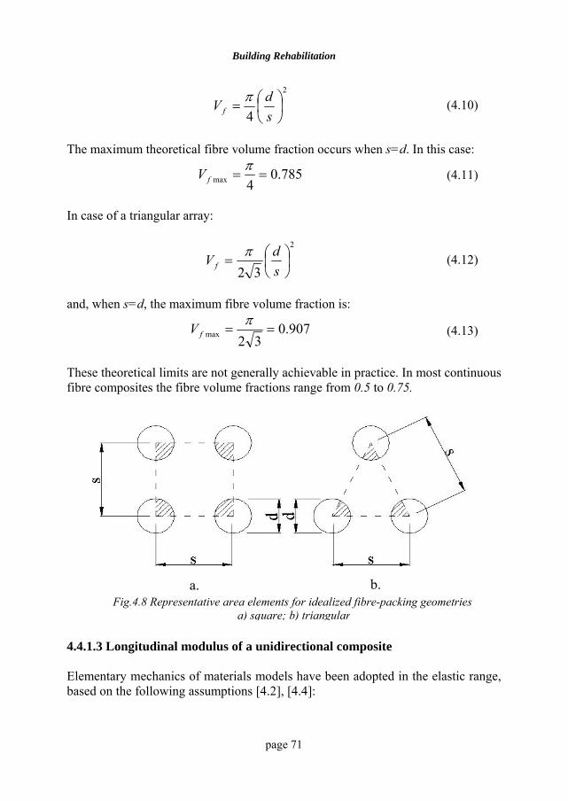
Building Rehabilitation
page 71
2
4⎟⎠⎞
⎜⎝⎛=
sdV f
π (4.10)
The maximum theoretical fibre volume fraction occurs when s=d. In this case:
785.04max ==π
fV (4.11)
In case of a triangular array:
2
32⎟⎠⎞
⎜⎝⎛=
sdV f
π (4.12)
and, when s=d, the maximum fibre volume fraction is:
907.032max ==
πfV (4.13)
These theoretical limits are not generally achievable in practice. In most continuous fibre composites the fibre volume fractions range from 0.5 to 0.75.
4.4.1.3 Longitudinal modulus of a unidirectional composite
Elementary mechanics of materials models have been adopted in the elastic range, based on the following assumptions [4.2], [4.4]:
Fig.4.8 Representative area elements for idealized fibre-packing geometries a) square; b) triangular
a. b.
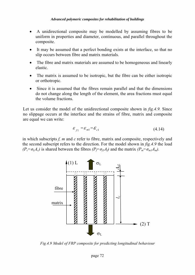
Advanced polymeric composites for rehabilitation of buildings
page 72
• A unidirectional composite may be modelled by assuming fibres to be uniform in properties and diameter, continuous, and parallel throughout the composite.
• It may be assumed that a perfect bonding exists at the interface, so that no slip occurs between fibre and matrix materials.
• The fibre and matrix materials are assumed to be homogeneous and linearly elastic.
• The matrix is assumed to be isotropic, but the fibre can be either isotropic or orthotropic.
• Since it is assumed that the fibres remain parallel and that the dimensions do not change along the length of the element, the area fractions must equal the volume fractions.
Let us consider the model of the unidirectional composite shown in fig.4.9. Since no slippage occurs at the interface and the strains of fibre, matrix and composite are equal we can write:
1fε = 1mε = 1cε (4.14)
in which subscripts f, m and c refer to fibre, matrix and composite, respectively and the second subscript refers to the direction. For the model shown in fig.4.9 the load (Pc=σLAc) is shared between the fibres (Pf=σf1Af) and the matrix (Pm=σm1Am).
Fig.4.9 Model of FRP composite for predicting longitudinal behaviour
fibre
matrix
l c
σL
σL
∆ cL
(2) T
(1) L
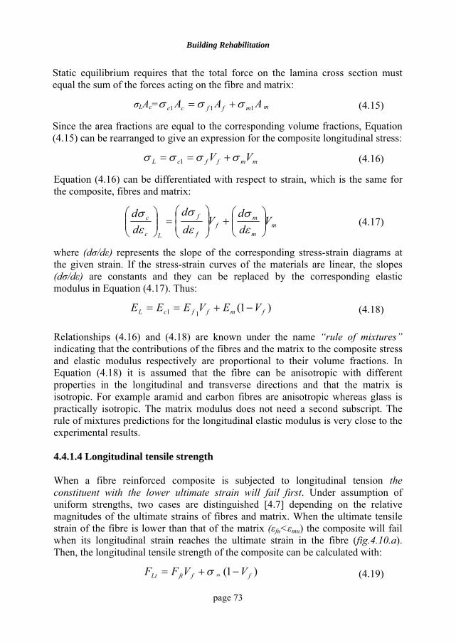
Building Rehabilitation
page 73
Static equilibrium requires that the total force on the lamina cross section must equal the sum of the forces acting on the fibre and matrix:
σLAc= AAA mffcc 111 σσσ += m (4.15)
Since the area fractions are equal to the corresponding volume fractions, Equation (4.15) can be rearranged to give an expression for the composite longitudinal stress:
mmffcL VV σσσσ +== 1 (4.16)
Equation (4.16) can be differentiated with respect to strain, which is the same for the composite, fibres and matrix:
mm
mf
f
f
Lc
c Vdd
Vdd
dd
⎟⎟⎠
⎞⎜⎜⎝
⎛+⎟
⎟⎠
⎞⎜⎜⎝
⎛=⎟⎟
⎠
⎞⎜⎜⎝
⎛εσ
εσ
εσ
(4.17)
where (dσ/dε) represents the slope of the corresponding stress-strain diagrams at the given strain. If the stress-strain curves of the materials are linear, the slopes (dσ/dε) are constants and they can be replaced by the corresponding elastic modulus in Equation (4.17). Thus:
)1(11 fmffcL VEVEEE −+== (4.18)
Relationships (4.16) and (4.18) are known under the name “rule of mixtures” indicating that the contributions of the fibres and the matrix to the composite stress and elastic modulus respectively are proportional to their volume fractions. In Equation (4.18) it is assumed that the fibre can be anisotropic with different properties in the longitudinal and transverse directions and that the matrix is isotropic. For example aramid and carbon fibres are anisotropic whereas glass is practically isotropic. The matrix modulus does not need a second subscript. The rule of mixtures predictions for the longitudinal elastic modulus is very close to the experimental results.
4.4.1.4 Longitudinal tensile strength
When a fibre reinforced composite is subjected to longitudinal tension the constituent with the lower ultimate strain will fail first. Under assumption of uniform strengths, two cases are distinguished [4.7] depending on the relative magnitudes of the ultimate strains of fibres and matrix. When the ultimate tensile strain of the fibre is lower than that of the matrix (εfu<εmu) the composite will fail when its longitudinal strain reaches the ultimate strain in the fibre (fig.4.10.a). Then, the longitudinal tensile strength of the composite can be calculated with:
)1( ffftLt VVFF m −+= σ (4.19)
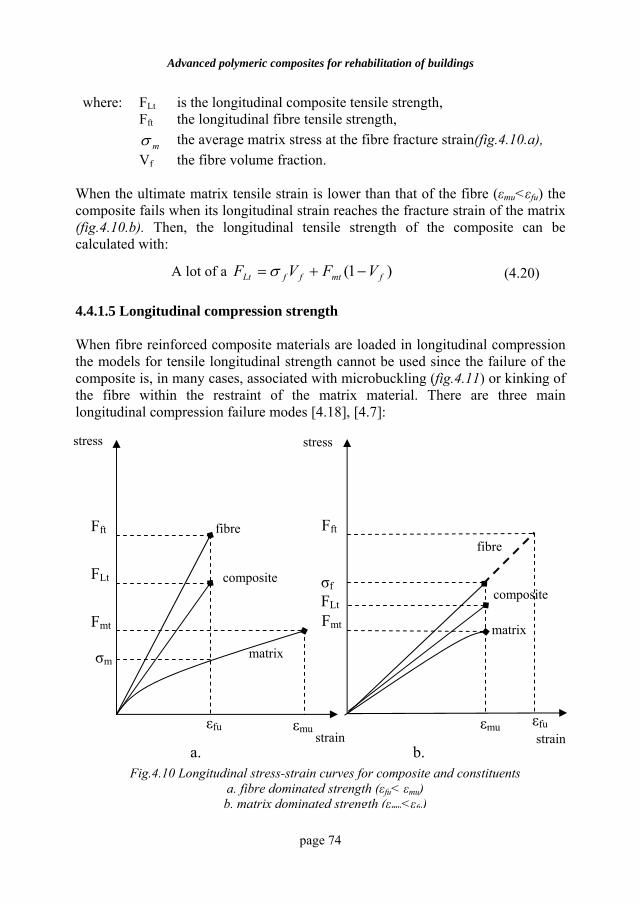
Advanced polymeric composites for rehabilitation of buildings
page 74
where: FLt is the longitudinal composite tensile strength, Fft the longitudinal fibre tensile strength,
mσ the average matrix stress at the fibre fracture strain(fig.4.10.a), Vf the fibre volume fraction.
When the ultimate matrix tensile strain is lower than that of the fibre (εmu<εfu) the composite fails when its longitudinal strain reaches the fracture strain of the matrix (fig.4.10.b). Then, the longitudinal tensile strength of the composite can be calculated with:
A lot of a )1( fmtffLt VFVF −+= σ (4.20)
4.4.1.5 Longitudinal compression strength
When fibre reinforced composite materials are loaded in longitudinal compression the models for tensile longitudinal strength cannot be used since the failure of the composite is, in many cases, associated with microbuckling (fig.4.11) or kinking of the fibre within the restraint of the matrix material. There are three main longitudinal compression failure modes [4.18], [4.7]:
εfu εmu
Fig.4.10 Longitudinal stress-strain curves for composite and constituents a. fibre dominated strength (εfu< εmu) b. matrix dominated strength (εmu<εfu)
a. b.
Fft
Fmt
σf
fibre
composite
matrix
Fft
FLt
Fmt
σm
εfu εmu
fibre
composite
matrix
stress
strain strain
stress
FLt
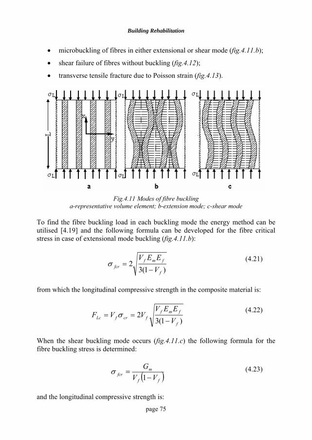
Building Rehabilitation
page 75
• microbuckling of fibres in either extensional or shear mode (fig.4.11.b);
• shear failure of fibres without buckling (fig.4.12);
• transverse tensile fracture due to Poisson strain (fig.4.13).
Fig.4.11 Modes of fibre buckling
a-representative volume element; b-extension mode; c-shear mode To find the fibre buckling load in each buckling mode the energy method can be utilised [4.19] and the following formula can be developed for the fibre critical stress in case of extensional mode buckling (fig.4.11.b):
)1(32
f
fmffcr V
EEV−
=σ (4.21)
from which the longitudinal compressive strength in the composite material is:
)1(32
f
fmffcrfLc V
EEVVVF
−== σ
(4.22)
When the shear buckling mode occurs (fig.4.11.c) the following formula for the fibre buckling stress is determined:
( )ff
mfcr VV
G−
=1
σ (4.23)
and the longitudinal compressive strength is:
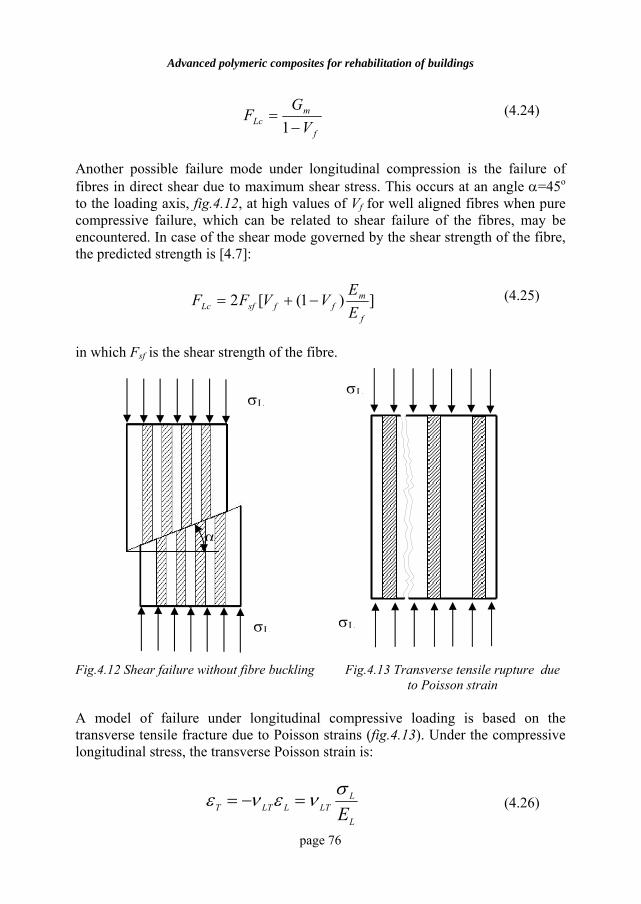
Advanced polymeric composites for rehabilitation of buildings
page 76
f
mLc V
GF
−=
1 (4.24)
Another possible failure mode under longitudinal compression is the failure of fibres in direct shear due to maximum shear stress. This occurs at an angle α=45o to the loading axis, fig.4.12, at high values of Vf for well aligned fibres when pure compressive failure, which can be related to shear failure of the fibres, may be encountered. In case of the shear mode governed by the shear strength of the fibre, the predicted strength is [4.7]:
])1([2f
mffsfLc E
EVVFF −+= (4.25)
in which Fsf is the shear strength of the fibre.
Fig.4.12 Shear failure without fibre buckling Fig.4.13 Transverse tensile rupture due to Poisson strain
A model of failure under longitudinal compressive loading is based on the transverse tensile fracture due to Poisson strains (fig.4.13). Under the compressive longitudinal stress, the transverse Poisson strain is:
=−= LLTT ενεL
LLT Eσν (4.26)
σL
σLσL
σL
α
Building Rehabilitation
page 77
and the compressive failure of a unidirectional fibre reinforced composite loaded in the fibre direction may be caused by transverse splitting of the material. At failure σL is the compressive strength (FLc) such that εT equals the ultimate transverse tensile strain (εTu) of the composite:
TuL
LLT E
εσν = (4.27)
and the corresponding formula for FLc is:
TuLT
LLc
EF ε
ν= (4.28)
The ultimate transverse strain of the composite can be calculated from the ultimate tensile strain [4.20] of the matrix (εmu):
)1( 3/1fmuTu V−= εε (4.29)
and the longitudinal compressive strength of the composite is [4.2]:
)1()1)](1([ 3/1
fmff
muffmffLc VV
VVEVEF
−+
−−+=
ννε
(4.30)
Experimental results are in better agreement with predictions of Equation (4.30) than with the predictions based on microbuckling of fibres.
4.4.1.6 Transverse modulus The transverse modulus is a matrix-dominated property being sensitive to the local state of stress. Let us consider a simple mathematical model shown in fig.4.14:
• The fibres are assumed to be uniform in properties and diameter, continuous and parallel throughout the composite.
• The composite is represented by a series model of matrix and fibre elements, and the main assumption is that the stress is the same in the fibre and matrix.
• Both constituents are assumed to be linear-elastic materials and the fibre-matrix bond is perfect.
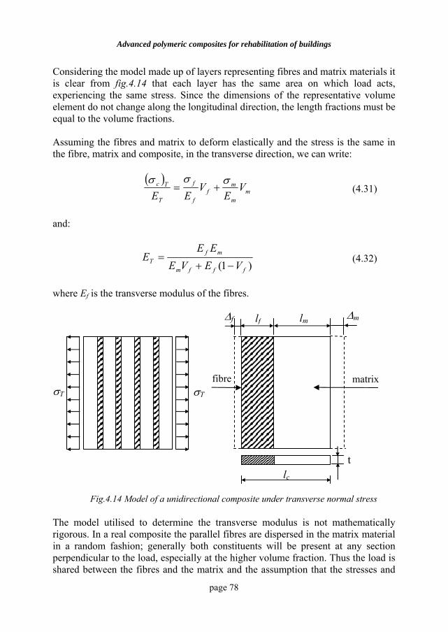
Advanced polymeric composites for rehabilitation of buildings
page 78
Considering the model made up of layers representing fibres and matrix materials it is clear from fig.4.14 that each layer has the same area on which load acts, experiencing the same stress. Since the dimensions of the representative volume element do not change along the longitudinal direction, the length fractions must be equal to the volume fractions. Assuming the fibres and matrix to deform elastically and the stress is the same in the fibre, matrix and composite, in the transverse direction, we can write:
( )m
m
mf
f
f
T
Tc VE
VEE
σσσ+= (4.31)
and:
)1( fffm
mfT VEVE
EEE
−+= (4.32)
where Ef is the transverse modulus of the fibres.
The model utilised to determine the transverse modulus is not mathematically rigorous. In a real composite the parallel fibres are dispersed in the matrix material in a random fashion; generally both constituents will be present at any section perpendicular to the load, especially at the higher volume fraction. Thus the load is shared between the fibres and the matrix and the assumption that the stresses and
fibre
Fig.4.14 Model of a unidirectional composite under transverse normal stress
matrix
lc
∆m
t
lf lm∆f
σT σT
Building Rehabilitation
page 79
the matrix are equal is inaccurate and the mechanics of materials prediction underestimates the transverse modulus. Halpin and Tsai [4.21] developed semi-empirical equations to match the results of more exact micromechanics analyses:
f
fmT V
VEE
1
11
11
ηηξ
−
+= (4.33)
where:
( )( ) 1
1
1ξ
η+−
=mf
mf
EEEE
(4.34)
and ξ1 is the reinforcing efficiency factor for transverse loading. For usual case of circular-section fibres, satisfactory results are obtained by taking ξ1=2. When ξ1=0, the Halpin-Tsai equation reduces to the inverse rule of mixtures, whereas a value of ξ=∞ yields the rule of mixtures.
4.4.1.7 Transverse tensile strength The transverse tensile loading is the most critical loading of a unidirectional composite. Many factors influence the transverse tensile strength and the most important are: the matrix strength, the fibre-matrix interface properties, and defects in matrix such as microcraks and voids. In case of transverse loading, the high-modulus fibres act as effective constraints [4.22] on the deformation of the matrix, causing stress and strain concentrations in this constituent and at the fibre-matrix interface, where the critical stresses and strains usually occur. An empirical approach [4.20] for the prediction of transverse tensile strength of fibrous composites leads to the formula given below:
)1( 3/1f
m
mtTTt V
EFE
F −= (4.35)
The preceding equation above assumes perfect adhesion between phases and thus failure occurs by matrix fracture at or near the interface. A reduction coefficient (Cv) to account for voids can be used [4.23] to modify Equation (4.35) and Cv can be determined with:
)1(41
f
vv V
VC−
−=π
(4.36)
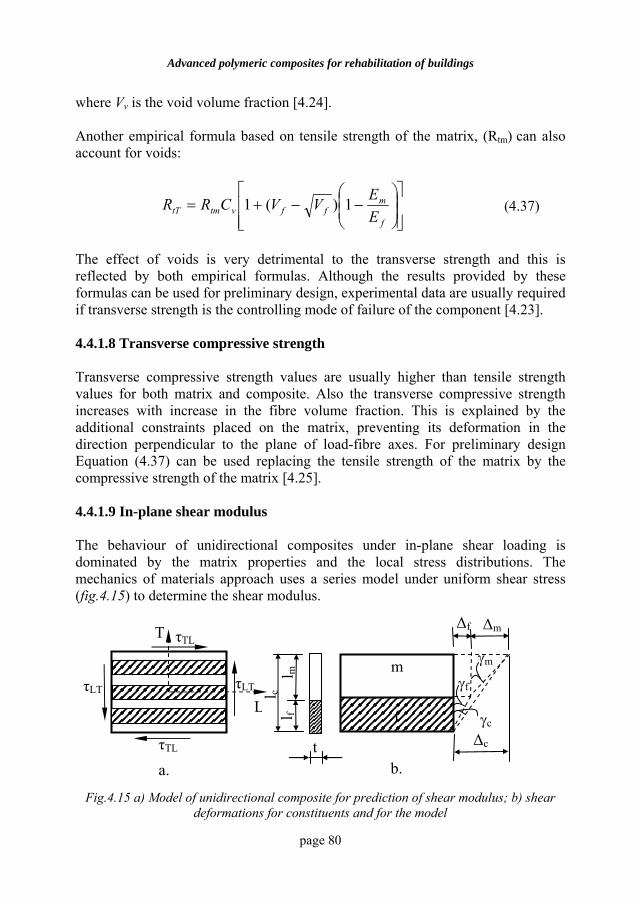
Advanced polymeric composites for rehabilitation of buildings
page 80
where Vv is the void volume fraction [4.24]. Another empirical formula based on tensile strength of the matrix, (Rtm) can also account for voids:
⎥⎥⎦
⎤
⎢⎢⎣
⎡⎟⎟⎠
⎞⎜⎜⎝
⎛−−+=
f
mffvtmtT E
EVVCRR 1)(1 (4.37)
The effect of voids is very detrimental to the transverse strength and this is reflected by both empirical formulas. Although the results provided by these formulas can be used for preliminary design, experimental data are usually required if transverse strength is the controlling mode of failure of the component [4.23].
4.4.1.8 Transverse compressive strength
Transverse compressive strength values are usually higher than tensile strength values for both matrix and composite. Also the transverse compressive strength increases with increase in the fibre volume fraction. This is explained by the additional constraints placed on the matrix, preventing its deformation in the direction perpendicular to the plane of load-fibre axes. For preliminary design Equation (4.37) can be used replacing the tensile strength of the matrix by the compressive strength of the matrix [4.25].
4.4.1.9 In-plane shear modulus
The behaviour of unidirectional composites under in-plane shear loading is dominated by the matrix properties and the local stress distributions. The mechanics of materials approach uses a series model under uniform shear stress (fig.4.15) to determine the shear modulus.
Fig.4.15 a) Model of unidirectional composite for prediction of shear modulus; b) shear deformations for constituents and for the model
t
l f l m
m
f
∆f ∆m
∆c
τLT
τTL
τTL
τLT
a. b.
L
T
l c
γf
γc
γm
Building Rehabilitation
page 81
Using the notations shown in fig.4.15 the total shear deformation of the composite, ∆c, is the sum of the shear deformations of the fibre, ∆f, and the matrix, ∆m; each shear deformation can be then expressed as the product of the corresponding shear strain (γc, γf, γm) and the cumulative widths of the material(lc, lf, lm):
mfc ∆+∆=∆ (4.38)
mmffcc lll γγγ += (4.39)
Dividing both sides of Equation (4.39) by lc and recognising that the width fraction is proportional to volume fractions, yields:
mmffc VV γγγ += (4.40)
Assuming linear shear stress-shear strain behaviour of fibres and matrix, the shear strains can be replaced by the ratios of shear stress and the corresponding shear modulus:
mm
mf
f
fc
LT
LT lG
lG
lG
τττ+= (4.41)
where GLT is the in-plane shear modulus of the composite, Gf is the shear modulus of fibres and Gm the shear modulus of matrix. But the shear stresses are equal on composite, fibres and matrix and from Equation (4.41) we obtain:
)1( fffm
mfLT VGVG
GGG
−+= (4.42)
As in the case of transverse modulus Equation (4.42) underestimates the values of the in-plane shear modulus, and the Halpin-Tsai equations can be used to give better predictions:
f
fmLT V
VGG
2
22
11
ηηξ
−+
= (4.43)
where:
( )( ) 2
2
1ξ
η+−
=mf
mf
GGGG
(4.44)
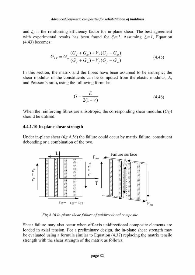
Advanced polymeric composites for rehabilitation of buildings
page 82
and ξ2 is the reinforcing efficiency factor for in-plane shear. The best agreement with experimental results has been found for ξ2=1. Assuming ξ2=1, Equation (4.43) becomes:
)()()()(
mffmf
mffmfmLT GGVGG
GGVGGGG
−−+−++
= (4.45)
In this section, the matrix and the fibres have been assumed to be isotropic; the shear modulus of the constituents can be computed from the elastic modulus, E, and Poisson’s ratio, using the following formula:
)1(2 ν+=
EG (4.46)
When the reinforcing fibres are anisotropic, the corresponding shear modulus (G12) should be utilised.
4.4.1.10 In-plane shear strength
Under in-plane shear (fig.4.16) the failure could occur by matrix failure, constituent debonding or a combination of the two.
Shear failure may also occur when off-axis unidirectional composite elements are loaded in axial tension. For a preliminary design, the in-plane shear strength may be evaluated using a formula similar to Equation (4.37) replacing the matrix tensile strength with the shear strength of the matrix as follows:
τ21= τLT
Fig.4.16 In-plane shear failure of unidirectional composite
τ12=
τ TL=
τ 21
Fms
Fms
Failure surface
τ 21=
τ TL
L
T
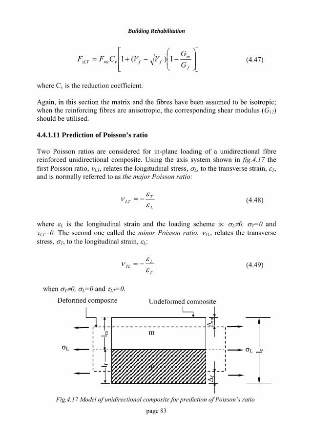
Building Rehabilitation
page 83
⎥⎥⎦
⎤
⎢⎢⎣
⎡⎟⎟⎠
⎞⎜⎜⎝
⎛−−+=
f
mffvmssLT G
GVVCFF 1)(1 (4.47)
where Cv is the reduction coefficient. Again, in this section the matrix and the fibres have been assumed to be isotropic; when the reinforcing fibres are anisotropic, the corresponding shear modulus (G12) should be utilised.
4.4.1.11 Prediction of Poisson’s ratio Two Poisson ratios are considered for in-plane loading of a unidirectional fibre reinforced unidirectional composite. Using the axis system shown in fig.4.17 the first Poisson ratio, νLT, relates the longitudinal stress, σL, to the transverse strain, εT, and is normally referred to as the major Poisson ratio:
L
TLT ε
εν −= (4.48)
where εL is the longitudinal strain and the loading scheme is: σL≠0, σT=0 and τLT=0. The second one called the minor Poisson ratio, νTL, relates the transverse stress, σT, to the longitudinal strain, εL:
T
LTL ε
εν −= (4.49)
when σT≠0, σL=0 and τLT=0.
Fig.4.17 Model of unidirectional composite for prediction of Poisson’s ratio
l f l m
∆ m
∆ f
σL σL l c
Deformed composite Undeformed composite
f
m
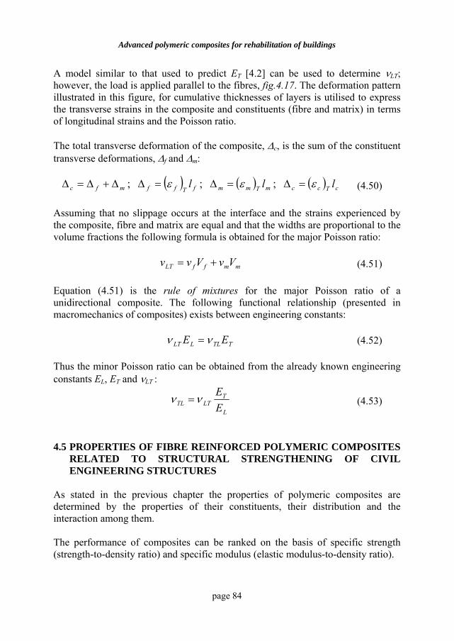
Advanced polymeric composites for rehabilitation of buildings
page 84
A model similar to that used to predict ET [4.2] can be used to determine νLT; however, the load is applied parallel to the fibres, fig.4.17. The deformation pattern illustrated in this figure, for cumulative thicknesses of layers is utilised to express the transverse strains in the composite and constituents (fibre and matrix) in terms of longitudinal strains and the Poisson ratio. The total transverse deformation of the composite, ∆c, is the sum of the constituent transverse deformations, ∆f and ∆m:
( ) ( ) ( ) cTccmTmmfTffmfc lll εεε =∆=∆=∆∆+∆=∆ ;;; (4.50) Assuming that no slippage occurs at the interface and the strains experienced by the composite, fibre and matrix are equal and that the widths are proportional to the volume fractions the following formula is obtained for the major Poisson ratio:
mmffLT VvVvv += (4.51) Equation (4.51) is the rule of mixtures for the major Poisson ratio of a unidirectional composite. The following functional relationship (presented in macromechanics of composites) exists between engineering constants:
TTLLLT EE νν = (4.52) Thus the minor Poisson ratio can be obtained from the already known engineering constants EL, ET and νLT :
L
TLTTL E
Eνν = (4.53)
4.5 PROPERTIES OF FIBRE REINFORCED POLYMERIC COMPOSITES
RELATED TO STRUCTURAL STRENGTHENING OF CIVIL ENGINEERING STRUCTURES
As stated in the previous chapter the properties of polymeric composites are determined by the properties of their constituents, their distribution and the interaction among them. The performance of composites can be ranked on the basis of specific strength (strength-to-density ratio) and specific modulus (elastic modulus-to-density ratio).
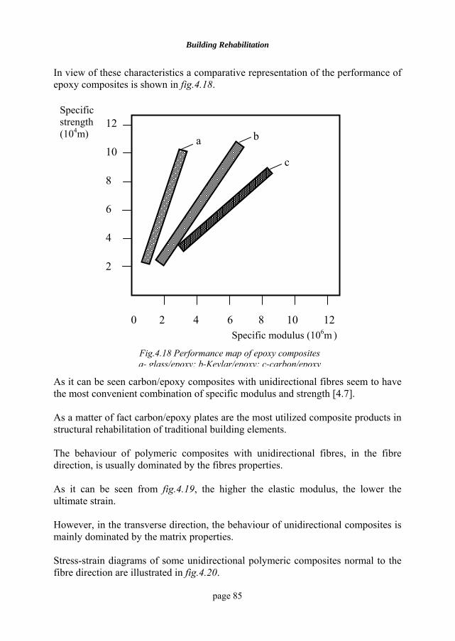
Building Rehabilitation
page 85
In view of these characteristics a comparative representation of the performance of epoxy composites is shown in fig.4.18.
As it can be seen carbon/epoxy composites with unidirectional fibres seem to have the most convenient combination of specific modulus and strength [4.7]. As a matter of fact carbon/epoxy plates are the most utilized composite products in structural rehabilitation of traditional building elements. The behaviour of polymeric composites with unidirectional fibres, in the fibre direction, is usually dominated by the fibres properties. As it can be seen from fig.4.19, the higher the elastic modulus, the lower the ultimate strain. However, in the transverse direction, the behaviour of unidirectional composites is mainly dominated by the matrix properties. Stress-strain diagrams of some unidirectional polymeric composites normal to the fibre direction are illustrated in fig.4.20.
0 2 4 6 8 10 12
12
10
8
6
4
2
a b
c
Specific strength (104m)
Specific modulus (106m )
Fig.4.18 Performance map of epoxy composites a- glass/epoxy; b-Kevlar/epoxy; c-carbon/epoxy
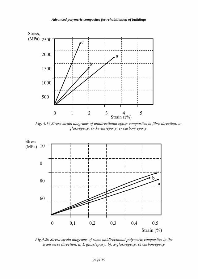
Advanced polymeric composites for rehabilitation of buildings
page 86
Fig. 4.19 Stress-strain diagrams of unidirectional epoxy composites in fibre direction: a-glass/epoxy; b- kevlar/epoxy; c- carbon/ epoxy.
0 0,1 0,2 0,3 0,4 0,5
10
0
80
60
Stress (MPa)
Strain (%)
a b
c
Fig.4.20 Stress-strain diagrams of some unidirectional polymeric composites in the transverse direction. a) E glass/epoxy; b). S-glass/epoxy; c) carbon/epoxy
Stress, (MPa)
0 1 2 3 4 5
2500
2000
1500
1000
500
c
b
a
Strain ε(%)
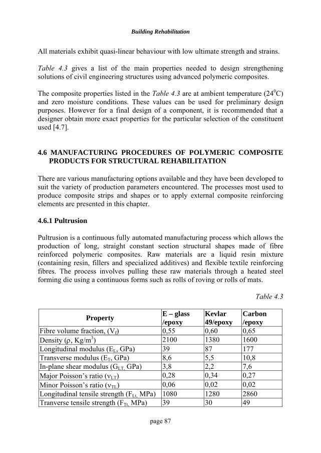
Building Rehabilitation
page 87
All materials exhibit quasi-linear behaviour with low ultimate strength and strains. Table 4.3 gives a list of the main properties needed to design strengthening solutions of civil engineering structures using advanced polymeric composites. The composite properties listed in the Table 4.3 are at ambient temperature (240C) and zero moisture conditions. These values can be used for preliminary design purposes. However for a final design of a component, it is recommended that a designer obtain more exact properties for the particular selection of the constituent used [4.7]. 4.6 MANUFACTURING PROCEDURES OF POLYMERIC COMPOSITE
PRODUCTS FOR STRUCTURAL REHABILITATION There are various manufacturing options available and they have been developed to suit the variety of production parameters encountered. The processes most used to produce composite strips and shapes or to apply external composite reinforcing elements are presented in this chapter. 4.6.1 Pultrusion Pultrusion is a continuous fully automated manufacturing process which allows the production of long, straight constant section structural shapes made of fibre reinforced polymeric composites. Raw materials are a liquid resin mixture (containing resin, fillers and specialized additives) and flexible textile reinforcing fibres. The process involves pulling these raw materials through a heated steel forming die using a continuous forms such as rolls of roving or rolls of mats.
Table 4.3
Property E – glass /epoxy
Kevlar 49/epoxy
Carbon /epoxy
Fibre volume fraction, (Vf) 0,55 0,60 0,65 Density (ρ, Kg/m3) 2100 1380 1600 Longitudinal modulus (EL, GPa) 39 87 177 Transverse modulus (ET, GPa) 8,6 5,5 10,8 In-plane shear modulus (GLT, GPa) 3,8 2,2 7,6 Major Poisson’s ratio (νLT) 0,28 0,34 0,27 Minor Poisson’s ratio (νTL) 0,06 0,02 0,02 Longitudinal tensile strength (FLt, MPa) 1080 1280 2860 Tranverse tensile strength (FTt, MPa) 39 30 49
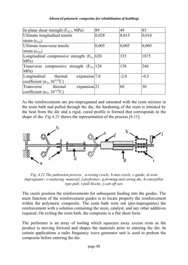
Advanced polymeric composites for rehabilitation of buildings
page 88
In-plane shear strength (FsLT, MPa) 89 49 83 Ultimate longitudinal tensile strain (εLtu)
0,028 0,015 0,016
Ultimate transverse tensile strain (εTtu)
0,005 0,005 0,005
Longitudinal compressive strength (FLc, MPa)
620 335 1875
Transverse compressive strength (FTc, MPa)
128 158 246
Longitudinal thermal expansion coefficient (α1, 10-6/0C)
7,0 -2,0 -0,3
Transverse thermal expansion coefficient (α2, 10-6/0C)
21 60 30
As the reinforcements are pre-impregnated and saturated with the resin mixture in the resin bath and pulled through the die, the hardening of the resin is initiated by the heat from the die and a rigid, cured profile is formed that corresponds to the shape of die. Fig.4.21 shows the representation of the process [4.11].
Fig. 4.21 The pultrusion process : a-roving creels; b-mat creels; c-guide; d-resin impregnator; e-surfacing material; f-preformer; g-forming and curing die; h-caterpillar
type pull; i-pull blocks; j-cutt off saw The creels position the reinforcements for subsequent feeding into the guides. The main function of the reinforcement guides is to locate properly the reinforcement within the polymeric composite. The resin bath wets out (pre-impregnates) the reinforcement with a solution containing the resin, catalyst, and any other additives required. On exiting the resin bath, the composite is a flat sheet form. The performer is an array of tooling which squeezes away excess resin as the product is moving forward and shapes the materials prior to entering the die. In certain applications a radio frequency wave generator unit is used to preheat the composite before entering the die.
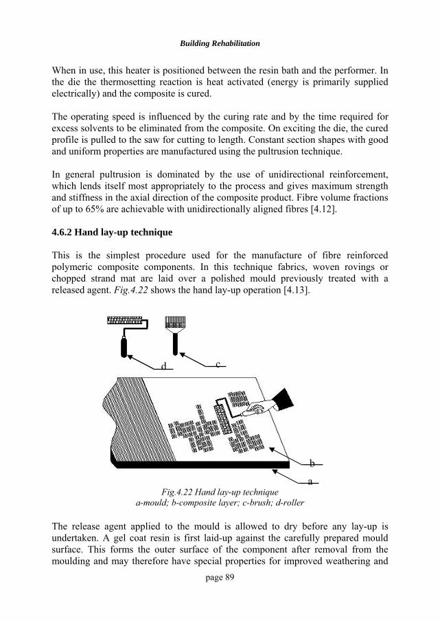
Building Rehabilitation
page 89
When in use, this heater is positioned between the resin bath and the performer. In the die the thermosetting reaction is heat activated (energy is primarily supplied electrically) and the composite is cured. The operating speed is influenced by the curing rate and by the time required for excess solvents to be eliminated from the composite. On exciting the die, the cured profile is pulled to the saw for cutting to length. Constant section shapes with good and uniform properties are manufactured using the pultrusion technique. In general pultrusion is dominated by the use of unidirectional reinforcement, which lends itself most appropriately to the process and gives maximum strength and stiffness in the axial direction of the composite product. Fibre volume fractions of up to 65% are achievable with unidirectionally aligned fibres [4.12].
4.6.2 Hand lay-up technique
This is the simplest procedure used for the manufacture of fibre reinforced polymeric composite components. In this technique fabrics, woven rovings or chopped strand mat are laid over a polished mould previously treated with a released agent. Fig.4.22 shows the hand lay-up operation [4.13].
Fig.4.22 Hand lay-up technique
a-mould; b-composite layer; c-brush; d-roller The release agent applied to the mould is allowed to dry before any lay-up is undertaken. A gel coat resin is first laid-up against the carefully prepared mould surface. This forms the outer surface of the component after removal from the moulding and may therefore have special properties for improved weathering and
d c
ba
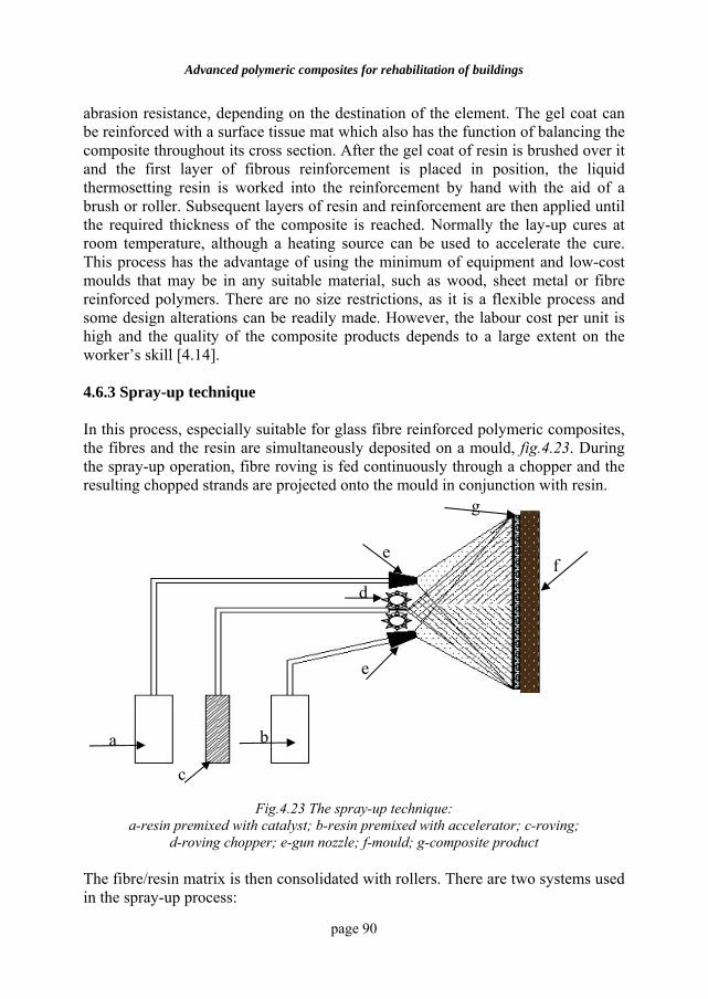
Advanced polymeric composites for rehabilitation of buildings
page 90
abrasion resistance, depending on the destination of the element. The gel coat can be reinforced with a surface tissue mat which also has the function of balancing the composite throughout its cross section. After the gel coat of resin is brushed over it and the first layer of fibrous reinforcement is placed in position, the liquid thermosetting resin is worked into the reinforcement by hand with the aid of a brush or roller. Subsequent layers of resin and reinforcement are then applied until the required thickness of the composite is reached. Normally the lay-up cures at room temperature, although a heating source can be used to accelerate the cure. This process has the advantage of using the minimum of equipment and low-cost moulds that may be in any suitable material, such as wood, sheet metal or fibre reinforced polymers. There are no size restrictions, as it is a flexible process and some design alterations can be readily made. However, the labour cost per unit is high and the quality of the composite products depends to a large extent on the worker’s skill [4.14]. 4.6.3 Spray-up technique In this process, especially suitable for glass fibre reinforced polymeric composites, the fibres and the resin are simultaneously deposited on a mould, fig.4.23. During the spray-up operation, fibre roving is fed continuously through a chopper and the resulting chopped strands are projected onto the mould in conjunction with resin.
Fig.4.23 The spray-up technique: a-resin premixed with catalyst; b-resin premixed with accelerator; c-roving;
d-roving chopper; e-gun nozzle; f-mould; g-composite product The fibre/resin matrix is then consolidated with rollers. There are two systems used in the spray-up process:
a
c
b
d
e
e
g
f
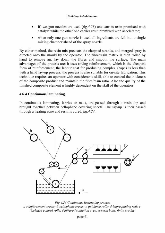
Building Rehabilitation
page 91
• if two gun nozzles are used (fig.4.23) one carries resin premixed with catalyst while the other one carries resin premixed with accelerator;
• when only one gun nozzle is used all ingredients are fed into a single mixing chamber ahead of the spray nozzle.
By either method, the resin mix precoats the chopped strands, and merged spray is directed onto the mould by the operator. The fibre/resin matrix is then rolled by hand to remove air, lay down the fibres and smooth the surface. The main advantages of the process are: it uses roving reinforcement, which is the cheapest form of reinforcement; the labour cost for producing complex shapes is less than with a hand lay-up process; the process is also suitable for on-site fabrication. This technique requires an operator with considerable skill, able to control the thickness of the composite product and maintain the fibre/resin ratio. Also the quality of the finished composite element is highly dependent on the skill of the operators. 4.6.4 Continuous laminating In continuous laminating, fabrics or mats, are passed through a resin dip and brought together between cellophane covering sheets. The lay-up is then passed through a heating zone and resin is cured, fig.4.24.
Fig.4.24 Continuous laminating process a-reinforcement creels; b-cellophane creels; c-guidance rolls; d-impregnating roll; e-
thickness control rolls; f-infrared radiation oven; g-resin bath; finite product
a
bb
c
d
e e f
g
h
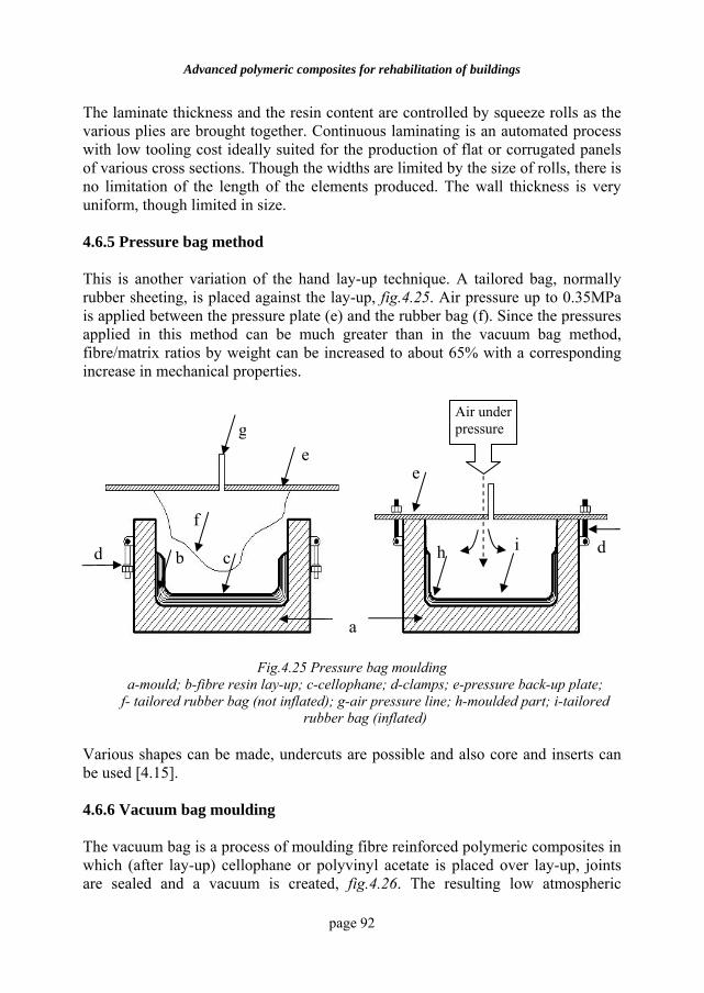
Advanced polymeric composites for rehabilitation of buildings
page 92
The laminate thickness and the resin content are controlled by squeeze rolls as the various plies are brought together. Continuous laminating is an automated process with low tooling cost ideally suited for the production of flat or corrugated panels of various cross sections. Though the widths are limited by the size of rolls, there is no limitation of the length of the elements produced. The wall thickness is very uniform, though limited in size. 4.6.5 Pressure bag method This is another variation of the hand lay-up technique. A tailored bag, normally rubber sheeting, is placed against the lay-up, fig.4.25. Air pressure up to 0.35MPa is applied between the pressure plate (e) and the rubber bag (f). Since the pressures applied in this method can be much greater than in the vacuum bag method, fibre/matrix ratios by weight can be increased to about 65% with a corresponding increase in mechanical properties.
Fig.4.25 Pressure bag moulding a-mould; b-fibre resin lay-up; c-cellophane; d-clamps; e-pressure back-up plate;
f- tailored rubber bag (not inflated); g-air pressure line; h-moulded part; i-tailored rubber bag (inflated)
Various shapes can be made, undercuts are possible and also core and inserts can be used [4.15]. 4.6.6 Vacuum bag moulding The vacuum bag is a process of moulding fibre reinforced polymeric composites in which (after lay-up) cellophane or polyvinyl acetate is placed over lay-up, joints are sealed and a vacuum is created, fig.4.26. The resulting low atmospheric
d
f
g
b c
ee
h i
Air under pressure
a
d
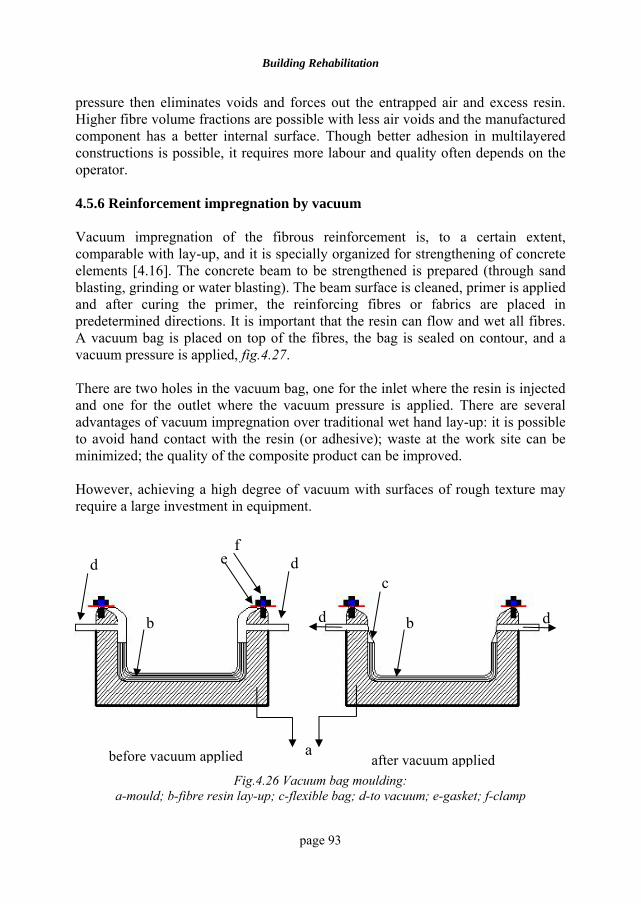
Building Rehabilitation
page 93
pressure then eliminates voids and forces out the entrapped air and excess resin. Higher fibre volume fractions are possible with less air voids and the manufactured component has a better internal surface. Though better adhesion in multilayered constructions is possible, it requires more labour and quality often depends on the operator. 4.5.6 Reinforcement impregnation by vacuum Vacuum impregnation of the fibrous reinforcement is, to a certain extent, comparable with lay-up, and it is specially organized for strengthening of concrete elements [4.16]. The concrete beam to be strengthened is prepared (through sand blasting, grinding or water blasting). The beam surface is cleaned, primer is applied and after curing the primer, the reinforcing fibres or fabrics are placed in predetermined directions. It is important that the resin can flow and wet all fibres. A vacuum bag is placed on top of the fibres, the bag is sealed on contour, and a vacuum pressure is applied, fig.4.27. There are two holes in the vacuum bag, one for the inlet where the resin is injected and one for the outlet where the vacuum pressure is applied. There are several advantages of vacuum impregnation over traditional wet hand lay-up: it is possible to avoid hand contact with the resin (or adhesive); waste at the work site can be minimized; the quality of the composite product can be improved. However, achieving a high degree of vacuum with surfaces of rough texture may require a large investment in equipment.
Fig.4.26 Vacuum bag moulding: a-mould; b-fibre resin lay-up; c-flexible bag; d-to vacuum; e-gasket; f-clamp
before vacuum applied after vacuum applied a
d
b
ef
d
d d b
c
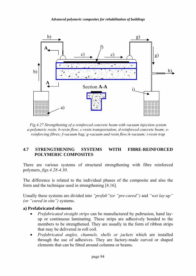
Advanced polymeric composites for rehabilitation of buildings
page 94
Fig.4.27 Strengthening of a reinforced concrete beam with vacuum injection system a-polymeric resin; b-resin flow; c-resin transportation; d-reinforced concrete beam; e-
reinforcing fibres; f-vacuum bag; g-vacuum and resin flow;h-vacuum; i-resin trap 4.7 STRENGTHENING SYSTEMS WITH FIBRE-REINFORCED
POLYMERIC COMPOSITES There are various systems of structural strengthening with fibre reinforced polymers, figs.4.28-4.30. The difference is related to the individual phases of the composite and also the form and the technique used in strengthening [4.16]. Usually these systems are divided into “prefab”(or “pre-cured”) and “wet lay-up” (or “cured in situ”) systems.
a) Prefabricated elements • Prefabricated straight strips can be manufactured by pultrusion, hand lay-
up or continuous laminating. These strips are adhesively bonded to the members to be strengthened. They are usually in the form of ribbon strips that may be delivered in roll coil.
• Prefabricated angles, channels, shells or jackets which are installed through the use of adhesives. They are factory-made curved or shaped elements that can be fitted around columns or beams.
a)
i)
b)
b)
c) c) f)
g)
g)
h)
A
A Section A-A
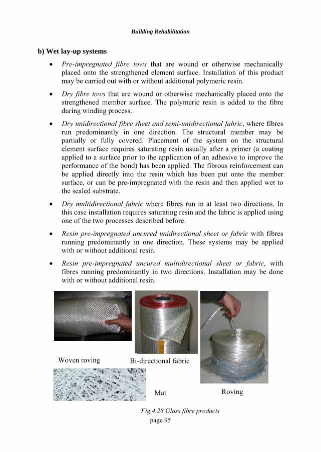
Building Rehabilitation
page 95
b) Wet lay-up systems
• Pre-impregnated fibre tows that are wound or otherwise mechanically placed onto the strengthened element surface. Installation of this product may be carried out with or without additional polymeric resin.
• Dry fibre tows that are wound or otherwise mechanically placed onto the strengthened member surface. The polymeric resin is added to the fibre during winding process.
• Dry unidirectional fibre sheet and semi-unidirectional fabric, where fibres run predominantly in one direction. The structural member may be partially or fully covered. Placement of the system on the structural element surface requires saturating resin usually after a primer (a coating applied to a surface prior to the application of an adhesive to improve the performance of the bond) has been applied. The fibrous reinforcement can be applied directly into the resin which has been put onto the member surface, or can be pre-impregnated with the resin and then applied wet to the sealed substrate.
• Dry multidirectional fabric where fibres run in at least two directions. In this case installation requires saturating resin and the fabric is applied using one of the two processes described before.
• Resin pre-impregnated uncured unidirectional sheet or fabric with fibres running predominantly in one direction. These systems may be applied with or without additional resin.
• Resin pre-impregnated uncured multidirectional sheet or fabric, with fibres running predominantly in two directions. Installation may be done with or without additional resin.
Woven roving Bi-directional fabric
Roving Mat
Fig.4.28 Glass fibre products
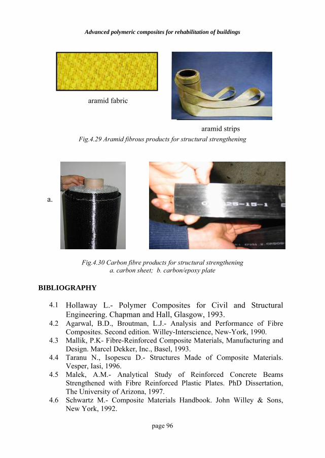
Advanced polymeric composites for rehabilitation of buildings
page 96
Fig.4.29 Aramid fibrous products for structural strengthening
Fig.4.30 Carbon fibre products for structural strengthening a. carbon sheet; b. carbon/epoxy plate
BIBLIOGRAPHY
4.1 Hollaway L.- Polymer Composites for Civil and Structural Engineering. Chapman and Hall, Glasgow, 1993.
4.2 Agarwal, B.D., Broutman, L.J.- Analysis and Performance of Fibre Composites. Second edition. Willey-Interscience, New-York, 1990.
4.3 Mallik, P.K- Fibre-Reinforced Composite Materials, Manufacturing and Design. Marcel Dekker, Inc., Basel, 1993.
4.4 Taranu N., Isopescu D.- Structures Made of Composite Materials. Vesper, Iasi, 1996.
4.5 Malek, A.M.- Analytical Study of Reinforced Concrete Beams Strengthened with Fibre Reinforced Plastic Plates. PhD Dissertation, The University of Arizona, 1997.
4.6 Schwartz M.- Composite Materials Handbook. John Willey & Sons, New York, 1992.
a. b.
aramid strips
aramid fabric
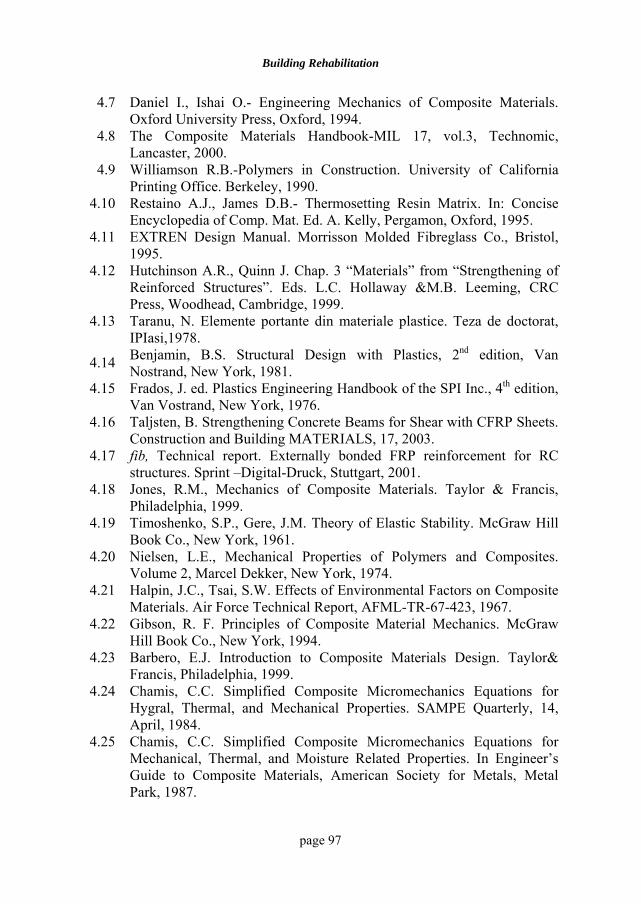
Building Rehabilitation
page 97
4.7 Daniel I., Ishai O.- Engineering Mechanics of Composite Materials. Oxford University Press, Oxford, 1994.
4.8 The Composite Materials Handbook-MIL 17, vol.3, Technomic, Lancaster, 2000.
4.9 Williamson R.B.-Polymers in Construction. University of California Printing Office. Berkeley, 1990.
4.10 Restaino A.J., James D.B.- Thermosetting Resin Matrix. In: Concise Encyclopedia of Comp. Mat. Ed. A. Kelly, Pergamon, Oxford, 1995.
4.11 EXTREN Design Manual. Morrisson Molded Fibreglass Co., Bristol, 1995.
4.12 Hutchinson A.R., Quinn J. Chap. 3 “Materials” from “Strengthening of Reinforced Structures”. Eds. L.C. Hollaway &M.B. Leeming, CRC Press, Woodhead, Cambridge, 1999.
4.13 Taranu, N. Elemente portante din materiale plastice. Teza de doctorat, IPIasi,1978.
4.14 Benjamin, B.S. Structural Design with Plastics, 2nd edition, Van Nostrand, New York, 1981.
4.15 Frados, J. ed. Plastics Engineering Handbook of the SPI Inc., 4th edition, Van Vostrand, New York, 1976.
4.16 Taljsten, B. Strengthening Concrete Beams for Shear with CFRP Sheets. Construction and Building MATERIALS, 17, 2003.
4.17 fib, Technical report. Externally bonded FRP reinforcement for RC structures. Sprint –Digital-Druck, Stuttgart, 2001.
4.18 Jones, R.M., Mechanics of Composite Materials. Taylor & Francis, Philadelphia, 1999.
4.19 Timoshenko, S.P., Gere, J.M. Theory of Elastic Stability. McGraw Hill Book Co., New York, 1961.
4.20 Nielsen, L.E., Mechanical Properties of Polymers and Composites. Volume 2, Marcel Dekker, New York, 1974.
4.21 Halpin, J.C., Tsai, S.W. Effects of Environmental Factors on Composite Materials. Air Force Technical Report, AFML-TR-67-423, 1967.
4.22 Gibson, R. F. Principles of Composite Material Mechanics. McGraw Hill Book Co., New York, 1994.
4.23 Barbero, E.J. Introduction to Composite Materials Design. Taylor& Francis, Philadelphia, 1999.
4.24 Chamis, C.C. Simplified Composite Micromechanics Equations for Hygral, Thermal, and Mechanical Properties. SAMPE Quarterly, 14, April, 1984.
4.25 Chamis, C.C. Simplified Composite Micromechanics Equations for Mechanical, Thermal, and Moisture Related Properties. In Engineer’s Guide to Composite Materials, American Society for Metals, Metal Park, 1987.
page 98
5 INFRASTRUCTURE CONSOLIDATION
5.1 GENERAL ASPECTS The following factors are to be taken into account when consolidating infrastructures:
i. the nature of the foundation soil;
ii. the groundwater level;
iii. the structure and the importance of the building;
iv. the foundation type and its present state;
v. the necessity of maintaining the building in service. Before starting the intervention works at the infrastructure level of a construction it is necessary to identify the cause. Thus, the intervention may be caused by:
• the aggressiveness of the ground waters or of the foundation soil,
• the increase in loads on foundations, by:
o changing the destination of the building,
o introducing additional floors,
o consolidation,
• the choice of an inappropriate foundation system,
• the decrease in the bearing capacity of the foundation soil, by:
o non-existing protection measures for buildings founded on moisture-sensitive soils,
o infiltrations of rain waters,
o the defective maintenance of the water supply, sewage, and heating systems,
• execution errors:
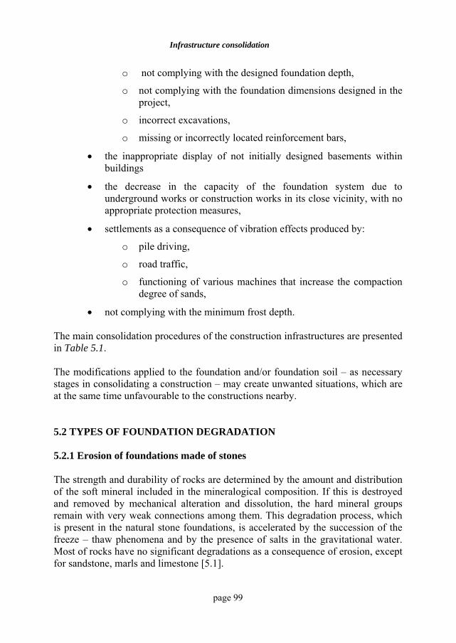
Infrastructure consolidation
page 99
o not complying with the designed foundation depth,
o not complying with the foundation dimensions designed in the project,
o incorrect excavations,
o missing or incorrectly located reinforcement bars,
• the inappropriate display of not initially designed basements within buildings
• the decrease in the capacity of the foundation system due to underground works or construction works in its close vicinity, with no appropriate protection measures,
• settlements as a consequence of vibration effects produced by:
o pile driving,
o road traffic,
o functioning of various machines that increase the compaction degree of sands,
• not complying with the minimum frost depth. The main consolidation procedures of the construction infrastructures are presented in Table 5.1. The modifications applied to the foundation and/or foundation soil – as necessary stages in consolidating a construction – may create unwanted situations, which are at the same time unfavourable to the constructions nearby. 5.2 TYPES OF FOUNDATION DEGRADATION 5.2.1 Erosion of foundations made of stones The strength and durability of rocks are determined by the amount and distribution of the soft mineral included in the mineralogical composition. If this is destroyed and removed by mechanical alteration and dissolution, the hard mineral groups remain with very weak connections among them. This degradation process, which is present in the natural stone foundations, is accelerated by the succession of the freeze – thaw phenomena and by the presence of salts in the gravitational water. Most of rocks have no significant degradations as a consequence of erosion, except for sandstone, marls and limestone [5.1].
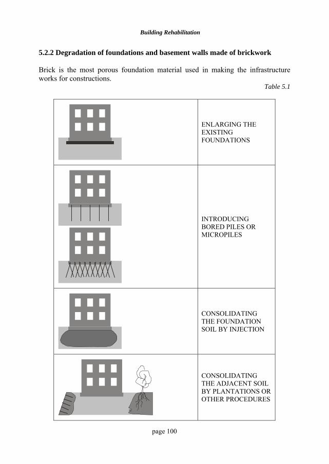
Building Rehabilitation
page 100
5.2.2 Degradation of foundations and basement walls made of brickwork Brick is the most porous foundation material used in making the infrastructure works for constructions.
Table 5.1
ENLARGING THE EXISTING FOUNDATIONS
INTRODUCING BORED PILES OR MICROPILES
CONSOLIDATING THE FOUNDATION SOIL BY INJECTION
CONSOLIDATING THE ADJACENT SOIL BY PLANTATIONS OR OTHER PROCEDURES
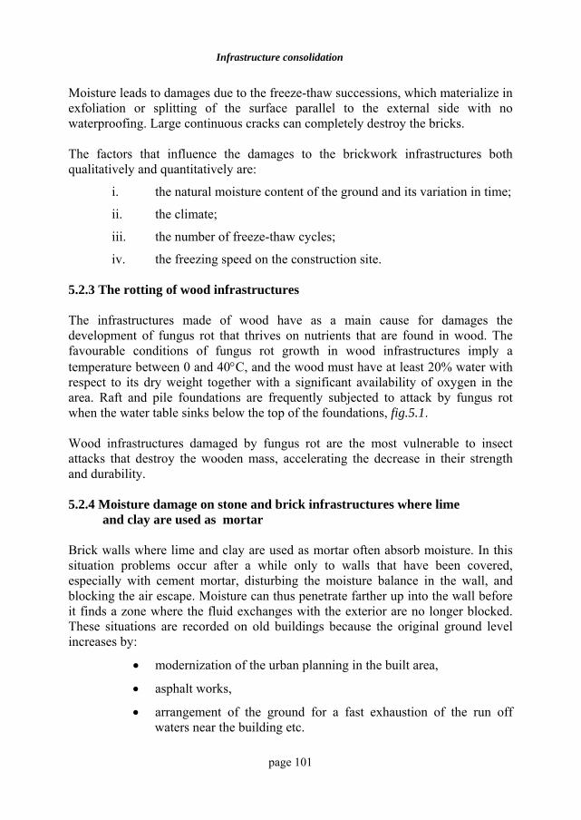
Infrastructure consolidation
page 101
Moisture leads to damages due to the freeze-thaw successions, which materialize in exfoliation or splitting of the surface parallel to the external side with no waterproofing. Large continuous cracks can completely destroy the bricks. The factors that influence the damages to the brickwork infrastructures both qualitatively and quantitatively are:
i. the natural moisture content of the ground and its variation in time;
ii. the climate;
iii. the number of freeze-thaw cycles;
iv. the freezing speed on the construction site. 5.2.3 The rotting of wood infrastructures The infrastructures made of wood have as a main cause for damages the development of fungus rot that thrives on nutrients that are found in wood. The favourable conditions of fungus rot growth in wood infrastructures imply a temperature between 0 and 40°C, and the wood must have at least 20% water with respect to its dry weight together with a significant availability of oxygen in the area. Raft and pile foundations are frequently subjected to attack by fungus rot when the water table sinks below the top of the foundations, fig.5.1. Wood infrastructures damaged by fungus rot are the most vulnerable to insect attacks that destroy the wooden mass, accelerating the decrease in their strength and durability. 5.2.4 Moisture damage on stone and brick infrastructures where lime
and clay are used as mortar Brick walls where lime and clay are used as mortar often absorb moisture. In this situation problems occur after a while only to walls that have been covered, especially with cement mortar, disturbing the moisture balance in the wall, and blocking the air escape. Moisture can thus penetrate farther up into the wall before it finds a zone where the fluid exchanges with the exterior are no longer blocked. These situations are recorded on old buildings because the original ground level increases by:
• modernization of the urban planning in the built area,
• asphalt works,
• arrangement of the ground for a fast exhaustion of the run off waters near the building etc.
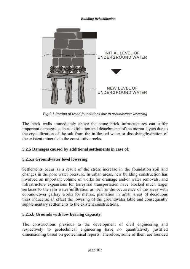
Building Rehabilitation
page 102
INITIAL LEVEL OF UNDERGROUND WATER
NEW LEVEL OF UNDERGROUND WATER
Fig.5.1 Rotting of wood foundations due to groundwater lowering
The brick walls immediately above the stone brick infrastructures can suffer important damages, such as exfoliation and detachments of the mortar layers due to the crystallization of the salt from the infiltrated water or dissolving/hydration of the existent minerals in the constitutive rocks. 5.2.5 Damages caused by additional settlements in case of: 5.2.5.a Groundwater level lowering Settlements occur as a result of the stress increase in the foundation soil and changes in the pore water pressure. In urban areas, new building construction has involved an important volume of works for drainage and/or water removals, and infrastructure expansions for terrestrial transportation have blocked much larger surfaces to the rain water infiltration as well as the occurrence of the areas with cut-and-cover gallery works for metros, plantation in urban areas of deciduous trees induce as an effect the lowering of the groundwater table and consequently supplementary settlements to the existent constructions. 5.2.5.b Grounds with low bearing capacity The constructions previous to the development of civil engineering and respectively to geotechnical engineering have no quantitatively justified dimensioning based on geotechnical reports. Therefore, some of them are founded
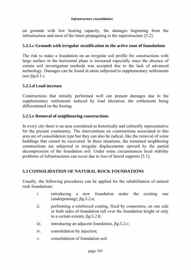
Infrastructure consolidation
page 103
on grounds with low bearing capacity, the damages beginning from the infrastructure and most of the times propagating to the superstructure [5.2]. 5.2.5.c Grounds with irregular stratification in the active zone of foundations The risk to make a foundation on an irregular soil profile for constructions with large surface in the horizontal plane is increased especially since the absence of certain soil investigation methods was accepted due to the lack of advanced technology. Damages can be found in areas subjected to supplementary settlements (see fig.6.1.). 5.2.5.d Load increase Constructions that initially performed well can present damages due to the supplementary settlements induced by load alteration, the settlements being differentiated on the footing. 5.2.5.e Removal of neighbouring constructions In every city there is an area considered as historically and culturally representative for the present community. The interventions on constructions associated to this area are of consolidation type but they can also be radical, like the removal of some buildings that cannot be recovered. In these situations, the remained neighboring constructions are subjected to irregular displacements upward by the partial decompression of the foundation soil. Under some circumstances local stability problems of infrastructures can occur due to loss of lateral supports [5.1]. 5.3 CONSOLIDATION OF NATURAL ROCK FOUNDATIONS Usually, the following procedures can be applied for the rehabilitation of natural rock foundations:
i. introducing a new foundation under the existing one (underpinning), fig.5.2.a;
ii. performing a reinforced coating, fixed by connectors, on one side or both sides of foundation (all over the foundation height or only to a certain extent), fig.5.2.b;
iii. introducing an adjacent foundation, fig.5.2.c;
iv. consolidation by injection;
v. consolidation of foundation soil.
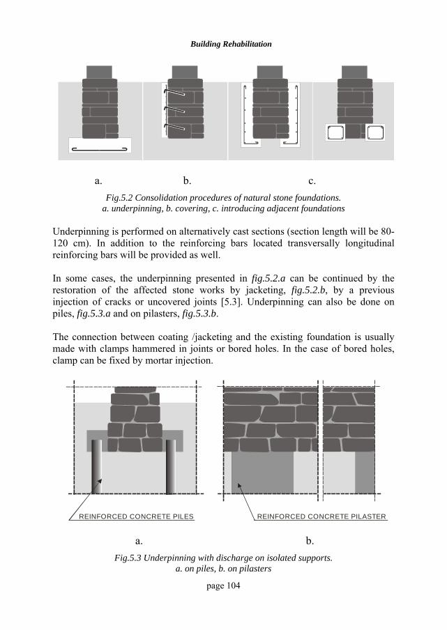
Building Rehabilitation
page 104
a. b. c.
Fig.5.2 Consolidation procedures of natural stone foundations. a. underpinning, b. covering, c. introducing adjacent foundations
Underpinning is performed on alternatively cast sections (section length will be 80-120 cm). In addition to the reinforcing bars located transversally longitudinal reinforcing bars will be provided as well. In some cases, the underpinning presented in fig.5.2.a can be continued by the restoration of the affected stone works by jacketing, fig.5.2.b, by a previous injection of cracks or uncovered joints [5.3]. Underpinning can also be done on piles, fig.5.3.a and on pilasters, fig.5.3.b. The connection between coating /jacketing and the existing foundation is usually made with clamps hammered in joints or bored holes. In the case of bored holes, clamp can be fixed by mortar injection.
REINFORCED CONCRETE PILES REINFORCED CONCRETE PILASTER
a. b.
Fig.5.3 Underpinning with discharge on isolated supports. a. on piles, b. on pilasters
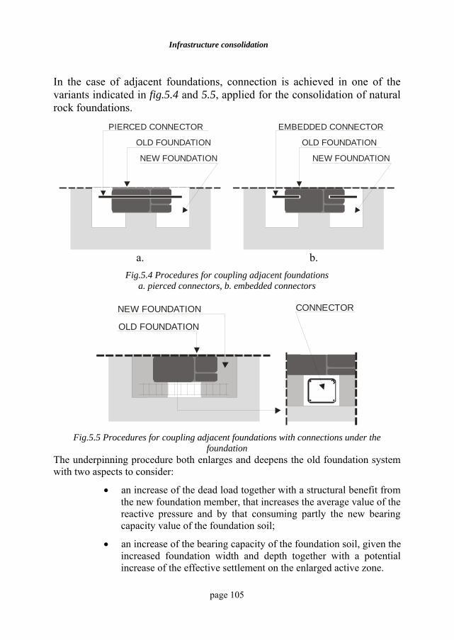
Infrastructure consolidation
page 105
In the case of adjacent foundations, connection is achieved in one of the variants indicated in fig.5.4 and 5.5, applied for the consolidation of natural rock foundations.
NEW FOUNDATION NEW FOUNDATION
OLD FOUNDATION OLD FOUNDATION
PIERCED CONNECTOR EMBEDDED CONNECTOR
a. b.
Fig.5.4 Procedures for coupling adjacent foundations a. pierced connectors, b. embedded connectors
NEW FOUNDATION
OLD FOUNDATION
CONNECTOR
Fig.5.5 Procedures for coupling adjacent foundations with connections under the
foundation The underpinning procedure both enlarges and deepens the old foundation system with two aspects to consider:
• an increase of the dead load together with a structural benefit from the new foundation member, that increases the average value of the reactive pressure and by that consuming partly the new bearing capacity value of the foundation soil;
• an increase of the bearing capacity of the foundation soil, given the increased foundation width and depth together with a potential increase of the effective settlement on the enlarged active zone.
Building Rehabilitation
page 106
The overall effect on safety factor is sometimes questionable when consolidating foundations without the active zone from the soil underneath. The technology related to the injection of natural rock foundations will be the same as the one applied in brickwork injections. When injecting natural rock foundations, the following aspects should be taken into account:
• fissures should not be too fine and should allow injection,
• fissures should not have clayey mud, since it influences the cement mortar setting and strengthening,
• the inserted mortar should not be in aggressive water or moving water,
• foundations will not be exposed to heat or moisture excess during injections based on lime mortar,
• if the foundations consolidated through this procedures are exposed to freeze-thaw cycles, they will be protected by introducing of continuous insulations on the external side.
5.4 CONSOLIDATION OF REINFORCED CONCRETE
FOUNDATIONS Reinforced concrete foundations generally require consolidation because of the existence of certain execution errors and more frequently due to load increase or foundation soil degradation. Usually, the rehabilitation of reinforced concrete foundations is achieved by introducing some adjacent foundations, which partially overtake the load from the existing foundations. The procedures of increasing the bearing capacity of the foundation soil are obviously applied too. In the case of continuous footings, the systems used are the same as those for natural stone foundations, fig.5.2.c and d, with the connecting systems in fig.5.4 and 5.5. A peripheral ring is introduced in the case of spread foundations [5.4], which can also contribute to the increase in soil bearing capacity. The ring can work independently with discharge on the existing foundation, fig.5.6.a or, when this is not possible, by direct coupling to the column bases, fig.5.6.b.
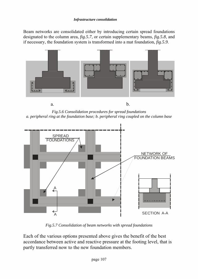
Infrastructure consolidation
page 107
Beam networks are consolidated either by introducing certain spread foundations designated to the column area, fig.5.7, or certain supplementary beams, fig.5.8, and if necessary, the foundation system is transformed into a mat foundation, fig.5.9.
a. b. Fig.5.6 Consolidation procedures for spread foundations
a. peripheral ring at the foundation base; b. peripheral ring coupled on the column base
SPREADFOUNDATIONS
NETWORK OF FOUNDATION BEAMS
A
A
SECTION A-A
Fig.5.7 Consolidation of beam networks with spread foundations Each of the various options presented above gives the benefit of the best accordance between active and reactive pressure at the footing level, that is partly transferred now to the new foundation members.
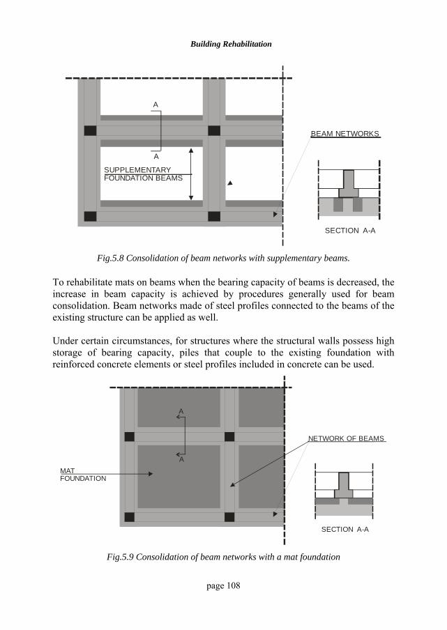
Building Rehabilitation
page 108
BEAM NETWORKS
SUPPLEMENTARYFOUNDATION BEAMS
A
A
SECTION A-A
Fig.5.8 Consolidation of beam networks with supplementary beams. To rehabilitate mats on beams when the bearing capacity of beams is decreased, the increase in beam capacity is achieved by procedures generally used for beam consolidation. Beam networks made of steel profiles connected to the beams of the existing structure can be applied as well. Under certain circumstances, for structures where the structural walls possess high storage of bearing capacity, piles that couple to the existing foundation with reinforced concrete elements or steel profiles included in concrete can be used.
NETWORK OF BEAMS
MATFOUNDATION
A
A
SECTION A-A
Fig.5.9 Consolidation of beam networks with a mat foundation
Infrastructure consolidation
page 109
5.5 TYPES OF PILES USED IN INFRASTRUCTURE CONSOLIDATIONS The development of various piling technologies offers the possibility of an optimal choice of the consolidation type used for the infrastructure of a certain construction based on the existing conditions. The hollow steel pile with circular cross-section or the piles made of steel profiles, externally protected against corrosion by a layer of 1,8 µm of epoxy resin, represent favourable solutions within the consolidation works [5.1]. They are introduced by light hammering, the work being performed from the inside and the minimum basement height required by the technology being 2.5 m. In the case of hollow piles, they are filled with concrete. The Mega-steel pile is a square steel pipe pile which is driven down into the soil with a hydraulic jack, the driving also being helped by local water flush. The section joints are made by welding. If the pile does not reach a soil layer of high consistency or the layer is not at the required depth, an enlarged base of plain concrete is performed. Concrete is pumped into the pile under pressure. Pressed or driven Mega piles of reinforced concrete have a square cross-section of the side of about 300 mm and the segment length of 1 m. These piles are usually used for constructions in soft rocks. The joints are made to give adequate bending capacity, generally by welding steel plates at the ends of each pile segment. The pile body has an included steel pipe in the cross-section centre, through which the verticality of the pile insertion is checked and the air or water flush can aid the pile driving. The Lindo piles are recommended in grounds consisting of hard rocks or other obstacles difficult to overcome by regular solutions. The pile consists of a removable steel pipe, which is introduced into the ground by drilling. Concrete is pumped into the pile when it has reached the required depth and a steel core is introduced with the dimensions varying from 50 to 100 mm. The load transmission from the existing foundation to the new pile group can be achieved through different variants. The direct location of piles under the existing foundation is more difficult. This solution is possible only by making slits and introducing the pile through the existing foundation, and then pouring the concrete in the joint zone. If the piles are located on the perimeter external to the existing foundation, a connecting beam will be made to include both piles and the body of the old foundation.
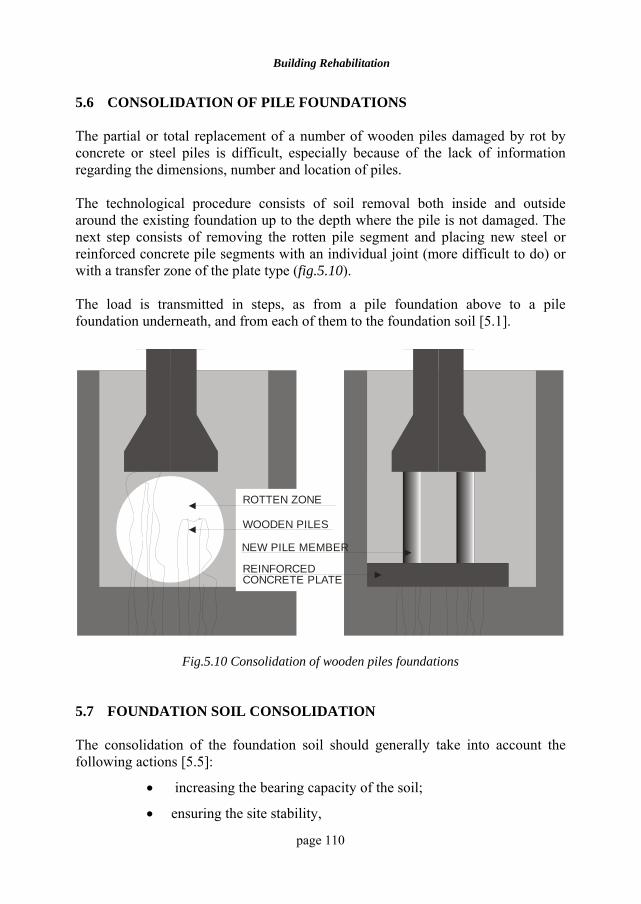
Building Rehabilitation
page 110
5.6 CONSOLIDATION OF PILE FOUNDATIONS The partial or total replacement of a number of wooden piles damaged by rot by concrete or steel piles is difficult, especially because of the lack of information regarding the dimensions, number and location of piles. The technological procedure consists of soil removal both inside and outside around the existing foundation up to the depth where the pile is not damaged. The next step consists of removing the rotten pile segment and placing new steel or reinforced concrete pile segments with an individual joint (more difficult to do) or with a transfer zone of the plate type (fig.5.10). The load is transmitted in steps, as from a pile foundation above to a pile foundation underneath, and from each of them to the foundation soil [5.1].
REINFORCEDCONCRETE PLATE
NEW PILE MEMBER
WOODEN PILES
ROTTEN ZONE
Fig.5.10 Consolidation of wooden piles foundations 5.7 FOUNDATION SOIL CONSOLIDATION The consolidation of the foundation soil should generally take into account the following actions [5.5]:
• increasing the bearing capacity of the soil;
• ensuring the site stability,
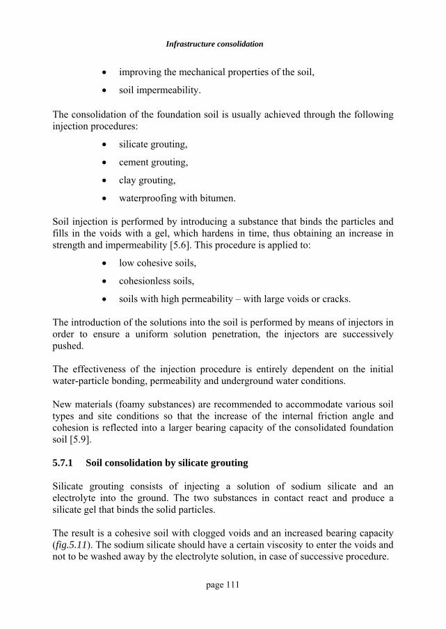
Infrastructure consolidation
page 111
• improving the mechanical properties of the soil,
• soil impermeability. The consolidation of the foundation soil is usually achieved through the following injection procedures:
• silicate grouting,
• cement grouting,
• clay grouting,
• waterproofing with bitumen. Soil injection is performed by introducing a substance that binds the particles and fills in the voids with a gel, which hardens in time, thus obtaining an increase in strength and impermeability [5.6]. This procedure is applied to:
• low cohesive soils,
• cohesionless soils,
• soils with high permeability – with large voids or cracks. The introduction of the solutions into the soil is performed by means of injectors in order to ensure a uniform solution penetration, the injectors are successively pushed. The effectiveness of the injection procedure is entirely dependent on the initial water-particle bonding, permeability and underground water conditions. New materials (foamy substances) are recommended to accommodate various soil types and site conditions so that the increase of the internal friction angle and cohesion is reflected into a larger bearing capacity of the consolidated foundation soil [5.9]. 5.7.1 Soil consolidation by silicate grouting Silicate grouting consists of injecting a solution of sodium silicate and an electrolyte into the ground. The two substances in contact react and produce a silicate gel that binds the solid particles. The result is a cohesive soil with clogged voids and an increased bearing capacity (fig.5.11). The sodium silicate should have a certain viscosity to enter the voids and not to be washed away by the electrolyte solution, in case of successive procedure.
Building Rehabilitation
page 112
INJECTOR
r
1.5
r
0.8 r
INJECTED AREA
Fig.5.11 The location of the injected zones
The silicate grouting with two solutions can be used in sands and sandy fine gravels with a permeability coefficient of 2.00 – 8.00 m/day. The silicate grouting is not recommended to:
• boulders, whose voids are not filled with fine materials,
• karstic voids,
• basaltic soils,
• soils logged with oil products, oil or raisins,
• soils with underground water whose pH is greater than 9. In loessy soils (containing carbonate or calcium sulphate) the sodium silicate reacts with the soluble salts in water, naturally included into the soil, resulting in the precipitation of the silica gel. The precipitation time of the silica gel can be modified from minutes to several hours by dosing the quantities and the solution concentrations. The silicate grouting can also be performed by adding inorganic reagents for fine and silty sands, with permeabilities between 0.1 and 10 m/day, or organic reagents for sands and fine pervious gravels [5.4], [5.7]. 5.7.2 Soil consolidation by cement grouting Cement grouting consists of an under pressure injection into the soil voids of cement grout or fluid mortar of cement, which reduces ground permeability and increases bearing capacity.
Infrastructure consolidation
page 113
This procedure is applied for soils whose particles can be bound with cement. The cement grouting can be used for gravels and sands where the voids are large enough to let the particles hydrated by cement break through. The size of the cement hydrated particles is about 50µ, and the soil that can be treated should have voids of at least 0.1 mm. The procedure can be applied if the value of the specific soil absorption is higher than 0.05 l/min. The mortars currently used have c/a dosages between 1:2 and 1:12, depending of the soil unit absorption. Calcium chloride may be added to accelerate the setting. The cement grout or mortar is introduced into the ground by injection. The spacing between injection points depends on the ground permeability and varies between 1.50 and 2.00m. The injection pressure is 3 – 5 at. Cement grouting gives unsatisfactory results in very aggressive soils or in soils with high salinity, since cement setting and hardening are hampered. 5.7.3 Ground consolidation by clay grouting Clay grouting consists of introducing a suspension or clayey paste into the soil by injection or caulking, which, once in the soil fissures, voids or pores, makes the soil clogged and impervious. Clay grouting is more economical in the ground with cages and large cracks, in rocks with numerous karstic voids, for which the performance of cement grouting provides important cement consumption and would thus be uneconomical. Clay grouting can be performed in soils with aggressive water; for clogging the fissured rocks and those with karstic voids, sandy clays with low plasticity are used. In this case, the use of fat clays is not recommended, as the suspensions made of these clays hardly release water and remain in fluid state inside the fissures. Therefore, they can be easily washed away by the water moving through the rock voids. In order to be injected, clay is processed by soaking and dispersion in water, as a suspension. By adding various chemical substances, dispersion time and coagulation of clay suspension can be controlled. Water release from the clay mortar can be accelerated by adding a coagulant during injection (calcium chloride, magnesium chloride, lime grout) of 3 – 5 % of the weight of the solid particles.
Building Rehabilitation
page 114
Clays and especially fat clays have the ability to exchange the ions from the adsorption complex in the presence of an electrolyte [8]. By adding a solution made from some calcium salt to a clayey suspension whose particles have sodium in the adsorption complex, sodium will be replaced by calcium ions and the suspension will coagulate. The presence of calcium and magnesium ions coagulates the clayey suspensions, while sodium and potassium ions make them more fluid. Clay – cement mixtures can be used in grounds consisting of boulders with large voids.
Mortar pumps are used to introduce clayey suspensions in sands and gravels. 5.7.4 Ground consolidation by bitumen grouting Bitumen grouting can be performed in cold and warm conditions. Bitumen grouting in warm conditions consists of under pressure injection of hot melted bitumen into the ground, at temperatures of 200- 2200C in order to:
• create impervious curtains,
• protect against water currents,
• protect against aggressive waters.
In contact with the rocks and the cold water moving through the void, bitumen hardens and cannot be washed away. Bitumen grouting in warm conditions is considered appropriate for hard rocks with cracks and voids for which the unit absorption of water varies between 0.1 and 100 l/min. The penetration radius of the hot melted bitumen depends on the fissure size and continuity, the ground permeability, the injecting pressure value and the injection duration. It should be taken into account that by cooling, bitumen reduces its volume by approx. 12 %. Bitumen grouting in cold conditions consists of injecting the ground with a bitumen emulsion. Chemical substances are added after the emulsion injection or at the same time with the ground penetration, breaking it. The salts from the underground water are often used to break the emulsion. The bitumen released (from the emulsions) groups, fills the voids between the particles and produces ground imperviousness.
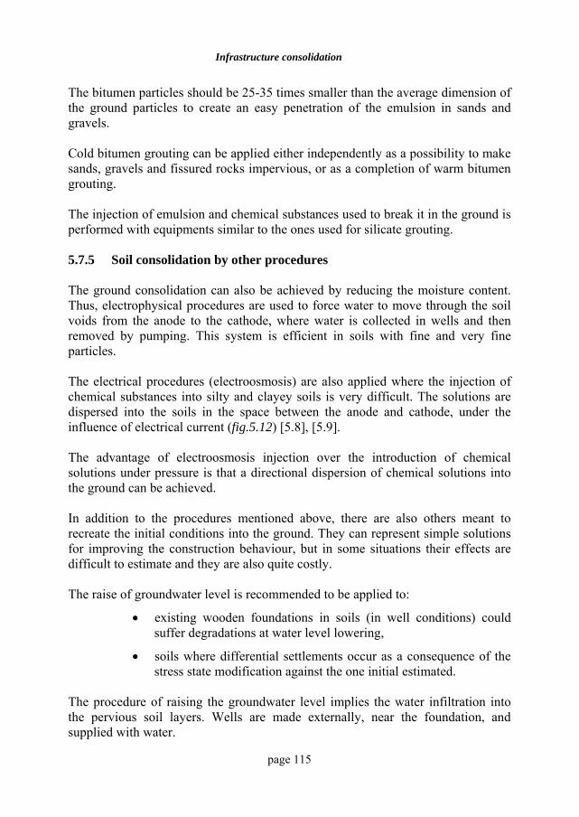
Infrastructure consolidation
page 115
The bitumen particles should be 25-35 times smaller than the average dimension of the ground particles to create an easy penetration of the emulsion in sands and gravels. Cold bitumen grouting can be applied either independently as a possibility to make sands, gravels and fissured rocks impervious, or as a completion of warm bitumen grouting. The injection of emulsion and chemical substances used to break it in the ground is performed with equipments similar to the ones used for silicate grouting. 5.7.5 Soil consolidation by other procedures The ground consolidation can also be achieved by reducing the moisture content. Thus, electrophysical procedures are used to force water to move through the soil voids from the anode to the cathode, where water is collected in wells and then removed by pumping. This system is efficient in soils with fine and very fine particles. The electrical procedures (electroosmosis) are also applied where the injection of chemical substances into silty and clayey soils is very difficult. The solutions are dispersed into the soils in the space between the anode and cathode, under the influence of electrical current (fig.5.12) [5.8], [5.9]. The advantage of electroosmosis injection over the introduction of chemical solutions under pressure is that a directional dispersion of chemical solutions into the ground can be achieved. In addition to the procedures mentioned above, there are also others meant to recreate the initial conditions into the ground. They can represent simple solutions for improving the construction behaviour, but in some situations their effects are difficult to estimate and they are also quite costly. The raise of groundwater level is recommended to be applied to:
• existing wooden foundations in soils (in well conditions) could suffer degradations at water level lowering,
• soils where differential settlements occur as a consequence of the stress state modification against the one initial estimated.
The procedure of raising the groundwater level implies the water infiltration into the pervious soil layers. Wells are made externally, near the foundation, and supplied with water.
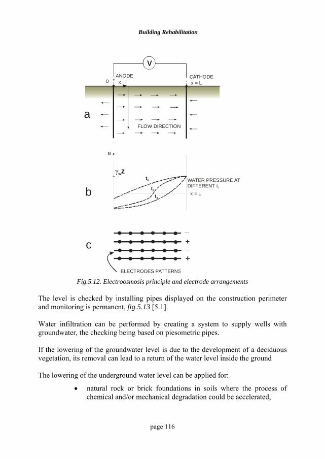
Building Rehabilitation
page 116
+ -
VANODE CATHODE
0 x = L
x = L
u
t1
t2
t3
γwzWATER PRESSURE AT DIFFERENT ti
FLOW DIRECTION
x
+
+_
_
ELECTRODES PATTERNS
a
b
c
Fig.5.12. Electroosmosis principle and electrode arrangements
The level is checked by installing pipes displayed on the construction perimeter and monitoring is permanent, fig.5.13 [5.1]. Water infiltration can be performed by creating a system to supply wells with groundwater, the checking being based on piesometric pipes. If the lowering of the groundwater level is due to the development of a deciduous vegetation, its removal can lead to a return of the water level inside the ground The lowering of the underground water level can be applied for:
• natural rock or brick foundations in soils where the process of chemical and/or mechanical degradation could be accelerated,
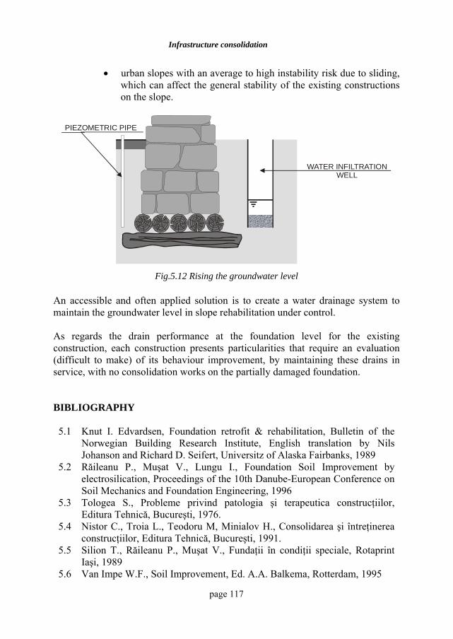
Infrastructure consolidation
page 117
• urban slopes with an average to high instability risk due to sliding, which can affect the general stability of the existing constructions on the slope.
WATER INFILTRATIONWELL
PIEZOMETRIC PIPE
Fig.5.12 Rising the groundwater level
An accessible and often applied solution is to create a water drainage system to maintain the groundwater level in slope rehabilitation under control. As regards the drain performance at the foundation level for the existing construction, each construction presents particularities that require an evaluation (difficult to make) of its behaviour improvement, by maintaining these drains in service, with no consolidation works on the partially damaged foundation. BIBLIOGRAPHY 5.1 Knut I. Edvardsen, Foundation retrofit & rehabilitation, Bulletin of the
Norwegian Building Research Institute, English translation by Nils Johanson and Richard D. Seifert, Universitz of Alaska Fairbanks, 1989
5.2 Răileanu P., Muşat V., Lungu I., Foundation Soil Improvement by electrosilication, Proceedings of the 10th Danube-European Conference on Soil Mechanics and Foundation Engineering, 1996
5.3 Tologea S., Probleme privind patologia şi terapeutica construcţiilor, Editura Tehnică, Bucureşti, 1976.
5.4 Nistor C., Troia L., Teodoru M, Minialov H., Consolidarea şi întreţinerea construcţiilor, Editura Tehnică, Bucureşti, 1991.
5.5 Silion T., Răileanu P., Muşat V., Fundaţii în condiţii speciale, Rotaprint Iaşi, 1989
5.6 Van Impe W.F., Soil Improvement, Ed. A.A. Balkema, Rotterdam, 1995
Building Rehabilitation
page 118
5.7 Răileanu P., Muşat V., Lungu I., The use of the electrosilication method at the foundation consolidations for old architectural monuments in Iaşi, Romania, Proceedings of the 2nd International Symposium-Grouting and Deep Mixing, Tokyo, 1996
5.8 Răileanu P., Boţi N., Stanciu A, Geologie, Geotehnică, Fundaţii, vol 1, 2, Rotaprint Iaşi, 1986
5.9 Lungu I., Stanciu A., Boţi N., Probleme Speciale de Geotehnică şi Fundaţii, Ed. Junimea, Iaşi, 2002
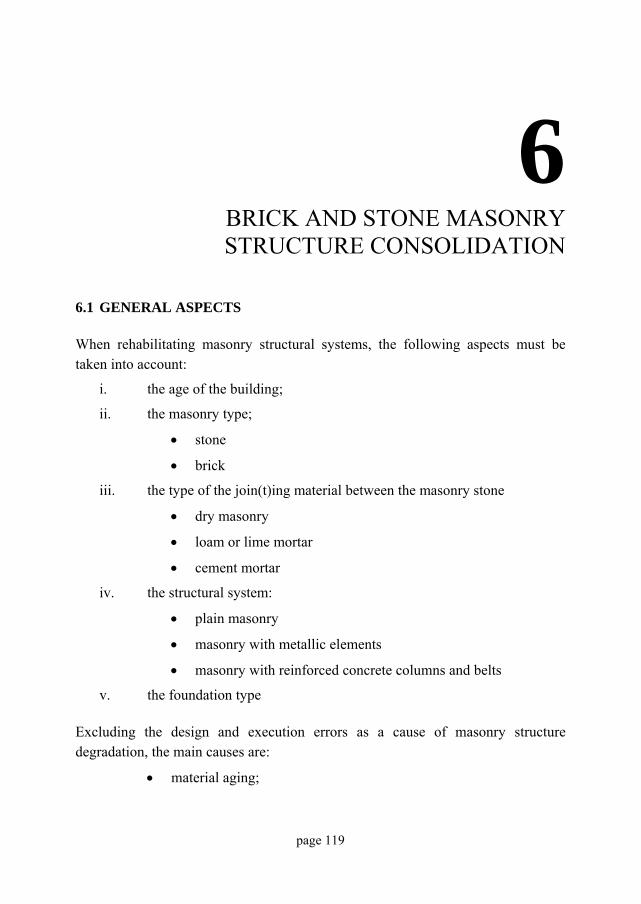
page 119
6
BRICK AND STONE MASONRY STRUCTURE CONSOLIDATION
6.1 GENERAL ASPECTS When rehabilitating masonry structural systems, the following aspects must be taken into account:
i. the age of the building;
ii. the masonry type;
• stone
• brick
iii. the type of the join(t)ing material between the masonry stone
• dry masonry
• loam or lime mortar
• cement mortar
iv. the structural system:
• plain masonry
• masonry with metallic elements
• masonry with reinforced concrete columns and belts
v. the foundation type Excluding the design and execution errors as a cause of masonry structure degradation, the main causes are:
• material aging;
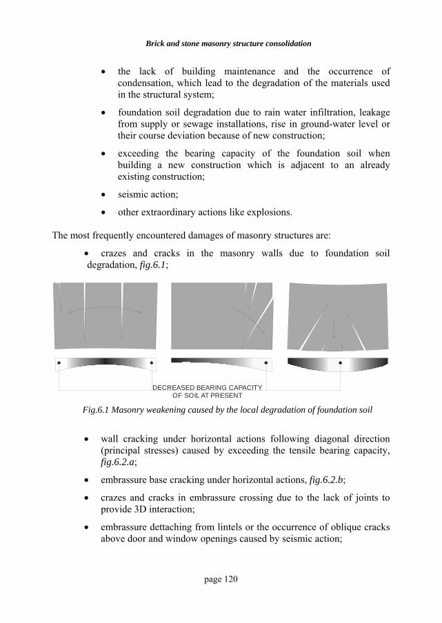
Brick and stone masonry structure consolidation
page 120
• the lack of building maintenance and the occurrence of condensation, which lead to the degradation of the materials used in the structural system;
• foundation soil degradation due to rain water infiltration, leakage from supply or sewage installations, rise in ground-water level or their course deviation because of new construction;
• exceeding the bearing capacity of the foundation soil when building a new construction which is adjacent to an already existing construction;
• seismic action;
• other extraordinary actions like explosions. The most frequently encountered damages of masonry structures are:
• crazes and cracks in the masonry walls due to foundation soil degradation, fig.6.1;
DECREASED BEARING CAPACITY OF SOIL AT PRESENT
Fig.6.1 Masonry weakening caused by the local degradation of foundation soil
• wall cracking under horizontal actions following diagonal direction (principal stresses) caused by exceeding the tensile bearing capacity, fig.6.2.a;
• embrassure base cracking under horizontal actions, fig.6.2.b;
• crazes and cracks in embrassure crossing due to the lack of joints to provide 3D interaction;
• embrassure dettaching from lintels or the occurrence of oblique cracks above door and window openings caused by seismic action;
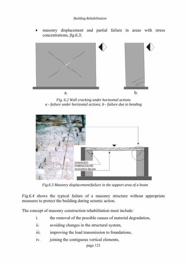
Building Rehabilitation
page 121
• masonry displacement and partial failure in areas with stress concentrations, fig.6.3;
a. b.
Fig. 6.2 Wall cracking under horizontal actions a - failure under horizontal actions; b - failure due to bending
Fig.6.3 Masonry displacement/failure in the support area of a beam
Fig.6.4 shows the typical failure of a masonry structure without appropriate measures to protect the building during seismic action. The concept of masonry construction rehabilitation must include:
i. the removal of the possible causes of material degradation,
ii. avoiding changes in the structural system,
iii. improving the load transmission to foundations,
iv. joining the contiguous vertical elements,
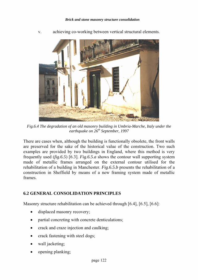
Brick and stone masonry structure consolidation
page 122
v. achieving co-working between vertical structural elements.
Fig.6.4 The degradation of an old masonry building in Umbria-Marche, Italy under the
earthquake on 26th September, 1997
There are cases when, although the building is functionally obsolete, the front walls are preserved for the sake of the historical value of the construction. Two such examples are provided by two buildings in England, where this method is very frequently used (fig.6.5) [6.3]. Fig.6.5.a shows the contour wall supporting system made of metallic frames arranged on the external contour utilised for the rehabilitation of a building in Manchester. Fig.6.5.b presents the rehabilitation of a construction in Sheffield by means of a new framing system made of metallic frames. 6.2 GENERAL CONSOLIDATION PRINCIPLES Masonry structure rehabilitation can be achieved through [6.4], [6.5], [6.6]:
• displaced masonry recovery;
• partial concreting with concrete denticulations;
• crack and craze injection and caulking;
• crack fastening with steel dogs;
• wall jacketing;
• opening planking;
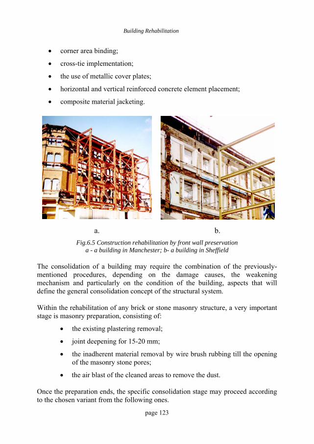
Building Rehabilitation
page 123
• corner area binding;
• cross-tie implementation;
• the use of metallic cover plates;
• horizontal and vertical reinforced concrete element placement;
• composite material jacketing.
a. b. Fig.6.5 Construction rehabilitation by front wall preservation
a - a building in Manchester; b- a building in Sheffield
The consolidation of a building may require the combination of the previously-mentioned procedures, depending on the damage causes, the weakening mechanism and particularly on the condition of the building, aspects that will define the general consolidation concept of the structural system.
Within the rehabilitation of any brick or stone masonry structure, a very important stage is masonry preparation, consisting of:
• the existing plastering removal;
• joint deepening for 15-20 mm;
• the inadherent material removal by wire brush rubbing till the opening of the masonry stone pores;
• the air blast of the cleaned areas to remove the dust. Once the preparation ends, the specific consolidation stage may proceed according to the chosen variant from the following ones.
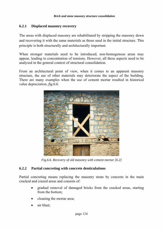
Brick and stone masonry structure consolidation
page 124
6.2.1 Displaced masonry recovery The areas with displaced masonry are rehabilitated by stripping the masonry down and recovering it with the same materials as those used in the initial structure. This principle is both structurally and architecturally important. When stronger materials need to be introduced, non-homogenous areas may appear, leading to concentration of tensions. However, all these aspects need to be analysed in the general context of structural consolidation.
From an architectural point of view, when it comes to an apparent masonry structure, the use of other materials may deteriorate the aspect of the building. There are many examples when the use of cement mortar resulted in historical value depreciation, fig.6.6.
Fig.6.6. Recovery of old masonry with cement mortar [6.2]
6.2.2 Partial concreting with concrete denticulations Partial concreting means replacing the masonry stone by concrete in the main cracked and crazed areas and consists of:
• gradual removal of damaged bricks from the cracked areas, starting from the bottom;
• cleaning the mortar area;
• air blast;
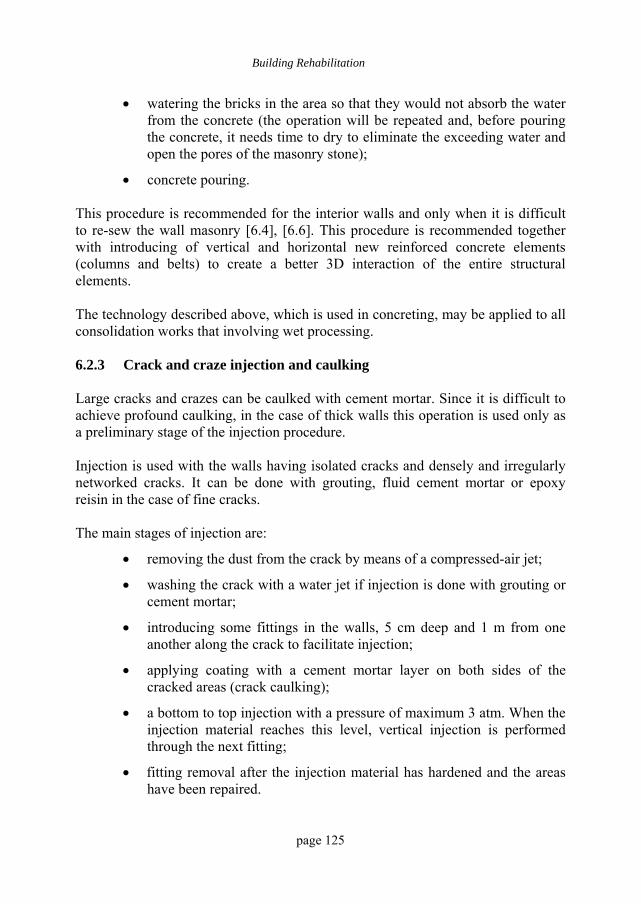
Building Rehabilitation
page 125
• watering the bricks in the area so that they would not absorb the water from the concrete (the operation will be repeated and, before pouring the concrete, it needs time to dry to eliminate the exceeding water and open the pores of the masonry stone);
• concrete pouring.
This procedure is recommended for the interior walls and only when it is difficult to re-sew the wall masonry [6.4], [6.6]. This procedure is recommended together with introducing of vertical and horizontal new reinforced concrete elements (columns and belts) to create a better 3D interaction of the entire structural elements. The technology described above, which is used in concreting, may be applied to all consolidation works that involving wet processing. 6.2.3 Crack and craze injection and caulking Large cracks and crazes can be caulked with cement mortar. Since it is difficult to achieve profound caulking, in the case of thick walls this operation is used only as a preliminary stage of the injection procedure.
Injection is used with the walls having isolated cracks and densely and irregularly networked cracks. It can be done with grouting, fluid cement mortar or epoxy reisin in the case of fine cracks.
The main stages of injection are:
• removing the dust from the crack by means of a compressed-air jet;
• washing the crack with a water jet if injection is done with grouting or cement mortar;
• introducing some fittings in the walls, 5 cm deep and 1 m from one another along the crack to facilitate injection;
• applying coating with a cement mortar layer on both sides of the cracked areas (crack caulking);
• a bottom to top injection with a pressure of maximum 3 atm. When the injection material reaches this level, vertical injection is performed through the next fitting;
• fitting removal after the injection material has hardened and the areas have been repaired.
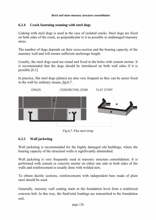
Brick and stone masonry structure consolidation
page 126
6.2.4 Crack fastening seaming with steel dogs Linking with steel dogs is used in the case of isolated cracks. Steel dogs are fixed on both sides of the crack, as perpendicular to it as possible in undamaged masonry areas. The number of dogs depends on their cross-section and the bearing capacity of the masonry wall and will ensure sufficient anchorage length. Usually, the steel dogs used are round and fixed in the holes with cement mortar. It is recommended that the dogs should be introduced on both wall sides if it is possible [6.1] In practice, flat steel dogs (plates) are also very frequent as they can be easier fixed in the wall by ordinary means, fig.6.7.
CRACK CONCRETING ZONE FLAT STRIP
Fig.6.7. Flat steel strap
6.2.5 Wall jacketing Wall jacketing is recommended for the highly damaged old buildings, where the bearing capacity of the structural walls is signifivantly diminished. Wall jacketing is very frequently used in masonry structure consolidation. It is performed with cement or concrete mortar on either one side or both sides of the walls and reinforcement is usually done with welded nets. To obtain ductile sections, reinforcements with independent bars made of plain steel should be used. Generally, masonry wall coating starts at the foundation level from a reinforced concrete belt. In this way, the final/total loadings are transmitted to the foundation soil.
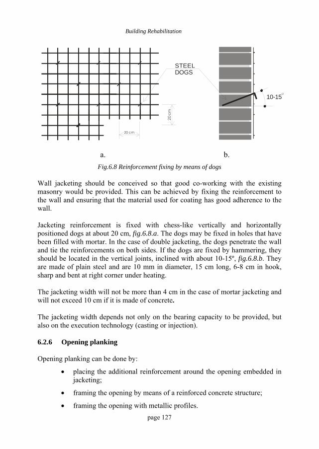
Building Rehabilitation
page 127
20
cm
20 cm
STEEL DOGS
10-15O
a. b.
Fig.6.8 Reinforcement fixing by means of dogs Wall jacketing should be conceived so that good co-working with the existing masonry would be provided. This can be achieved by fixing the reinforcement to the wall and ensuring that the material used for coating has good adherence to the wall. Jacketing reinforcement is fixed with chess-like vertically and horizontally positioned dogs at about 20 cm, fig.6.8.a. The dogs may be fixed in holes that have been filled with mortar. In the case of double jacketing, the dogs penetrate the wall and tie the reinforcements on both sides. If the dogs are fixed by hammering, they should be located in the vertical joints, inclined with about 10-15º, fig.6.8.b. They are made of plain steel and are 10 mm in diameter, 15 cm long, 6-8 cm in hook, sharp and bent at right corner under heating. The jacketing width will not be more than 4 cm in the case of mortar jacketing and will not exceed 10 cm if it is made of concrete. The jacketing width depends not only on the bearing capacity to be provided, but also on the execution technology (casting or injection). 6.2.6 Opening planking Opening planking can be done by:
• placing the additional reinforcement around the opening embedded in jacketing;
• framing the opening by means of a reinforced concrete structure;
• framing the opening with metallic profiles.
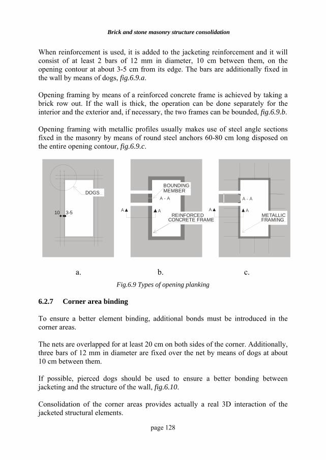
Brick and stone masonry structure consolidation
page 128
When reinforcement is used, it is added to the jacketing reinforcement and it will consist of at least 2 bars of 12 mm in diameter, 10 cm between them, on the opening contour at about 3-5 cm from its edge. The bars are additionally fixed in the wall by means of dogs, fig.6.9.a. Opening framing by means of a reinforced concrete frame is achieved by taking a brick row out. If the wall is thick, the operation can be done separately for the interior and the exterior and, if necessary, the two frames can be bounded, fig.6.9.b. Opening framing with metallic profiles usually makes use of steel angle sections fixed in the masonry by means of round steel anchors 60-80 cm long disposed on the entire opening contour, fig.6.9.c.
A A
A - A
A A
A - A
10 3-5
DOGSBOUNDINGMEMBER
RAMA DIN BETON ARMATREINFORCED
CONCRETE FRAMEMETALLICFRAMING
a. b. c. Fig.6.9 Types of opening planking
6.2.7 Corner area binding To ensure a better element binding, additional bonds must be introduced in the corner areas. The nets are overlapped for at least 20 cm on both sides of the corner. Additionally, three bars of 12 mm in diameter are fixed over the net by means of dogs at about 10 cm between them. If possible, pierced dogs should be used to ensure a better bonding between jacketing and the structure of the wall, fig.6.10. Consolidation of the corner areas provides actually a real 3D interaction of the jacketed structural elements.
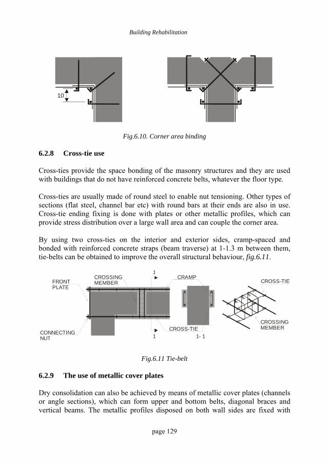
Building Rehabilitation
page 129
10
Fig.6.10. Corner area binding
6.2.8 Cross-tie use Cross-ties provide the space bonding of the masonry structures and they are used with buildings that do not have reinforced concrete belts, whatever the floor type. Cross-ties are usually made of round steel to enable nut tensioning. Other types of sections (flat steel, channel bar etc) with round bars at their ends are also in use. Cross-tie ending fixing is done with plates or other metallic profiles, which can provide stress distribution over a large wall area and can couple the corner area. By using two cross-ties on the interior and exterior sides, cramp-spaced and bonded with reinforced concrete straps (beam traverse) at 1-1.3 m between them, tie-belts can be obtained to improve the overall structural behaviour, fig.6.11.
CROSSINGMEMBER
CROSSINGMEMBER
CRAMP
CROSS-TIE
FRONTPLATE
CONNECTINGNUT
1
1 1- 1
CROSS-TIE
Fig.6.11 Tie-belt 6.2.9 The use of metallic cover plates Dry consolidation can also be achieved by means of metallic cover plates (channels or angle sections), which can form upper and bottom belts, diagonal braces and vertical beams. The metallic profiles disposed on both wall sides are fixed with
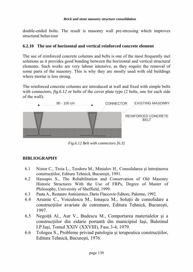
Brick and stone masonry structure consolidation
page 130
double-ended bolts. The result is masonry wall pre-stressing which improves structural behaviour 6.2.10 The use of horizontal and vertical reinforced concrete element The use of reinforced concrete columns and belts is one of the most frequently met solutions as it provides good bonding between the horizontal and vertical structural elements. Such works are very labour intensive, as they require the removal of some parts of the masonry. This is why they are mostly used with old buildings where mortar is less strong. The reinforced concrete columns are introduced at wall and fixed with simple belts with connectors, fig.6.12 or belts of the cover plate type (2 belts, one for each side of the wall).
EXISTING MASONRY80 - 100 cm
REINFORCED CONCRETE BELT
CONNECTOR
Fig.6.12 Belt with connectors [6.3]
BIBLIOGRAPHY 6.1 Nistor C., Troia L., Teodoru M., Minialov H., Consolidarea şi întreţinerea
construcţiilor, Editura Tehnică, Bucureşti, 1991. 6.2 Hassapis S., The Rehabilitation and Conservation of Old Masonry
Historic Structures With the Use of FRPs, Degree of Master of Philosophy, University of Sheffield, 1999.
6.3 Pasta A., Restauro Antisismico, Dario Flaccovio Editore, Palermo, 1992. 6.4 Arsenie C., Voiculescu M., Ionaşcu M., Soluţii de consolidare a
construcţiilor avariate de cutremure, Editura Tehnică, Bucureşti, 1997.
6.5 Negoiţă Al., Aur V., Budescu M., Comportarea materialelor şi a construcţiilor din zidarie portantă din municipiul Iaşi, Buletinul I.P.Iaşi, Tomul XXIV (XXVIII), Fasc.3-4, 1979.
6.6 Tologea S., Probleme privind patologia şi terapeutica construcţiilor, Editura Tehnică, Bucureşti, 1976.
page 131
7 REHABILITATION OF
REINFORCED CONCRETE STRUCTURES
7.1 GENERAL ASPECTS Buildings with reinforced concrete structures are largely used in most countries. Although these types of structures have a high degree of safety, the cases when intervention is needed to rehabilitate them are very frequent. The causes of degradation of reinforced concrete structures are not few. The most frequent damages are caused by defective performances during execution, such as:
• certain operations performed in cold or hot weather conditions without taking proper measures to ensure the quality of concrete;
• incorrect disposal of the reinforcing bars in compliance with the execution project;
• formwork removal or stressing of the structural element before reaching the required concrete strength;
• use of low quality materials;
• failure to comply with the technologies when casting the concrete.
The group of construction errors that may have unpleasant effects on the reinforced concrete structures also includes errors related to the quality of the adjacent works like jacketing, finishing etc.
Sometimes the causes of degradation of reinforced concrete structures and of other types of structures as well may occur even from the design stage. Some of them are:
• loading underestimation related to the destination of the building or the change in its destination;
• incorrect analytic modelling and calculus errors;
Rehabilitation of reinforced concrete structures
page 132
• structural errors, such as the lack of plastic deformation capacity (non-ductile sections) for the buildings situated in seismic areas;
• conceiving errors related to thermal coating/insulations and heating systems;
• accepting some inadequate structural systems suggested by the architects.
Damages are often caused by technological actions or the improper maintenance of equipment and installations, sometimes accompanied by material aging. Most examples of this type are found in industry, where damage may be caused by:
• chemical agents;
• poor maintenance of installations producing vibrations;
• infiltration of chemical agents into the groundwater and infrastructure failure;
• technological operations that release aggressive chemical substances;
• excessive humidity and the absence of ventilation systems
• failure to comply with the climatic conditions (condensation) etc.
There are also other factors which, either by degradation in the foundation soil and water infiltration as leakage from water supply systems, or degradation at the hydro-and thermal level of coatings can make the structures lose their functioning capacity (e.g. the loss of their capacity of retaining liquids in tanks or retaining water at dams) or local failures into the structure itself.
However, most structural damages occur in seismic areas. The causes of reinforced concrete structure degradation under seismic actions are very numerous. Many old buildings, which have been subjected to a relatively high number of earthquakes, have lost their bearing capacity because of material fatigue. The concept of ductile design itself, which lies at the basis of construction design in seismic areas, accepts minor structural damages during earthquakes, which will require afterwards, interventions.
7.2 GENERAL REHABILITATION PRINCIPLES
Rehabilitation of reinforced concrete structures may be achieved in several ways. However, the performance of the new system is constrained by a series of factors, such as:
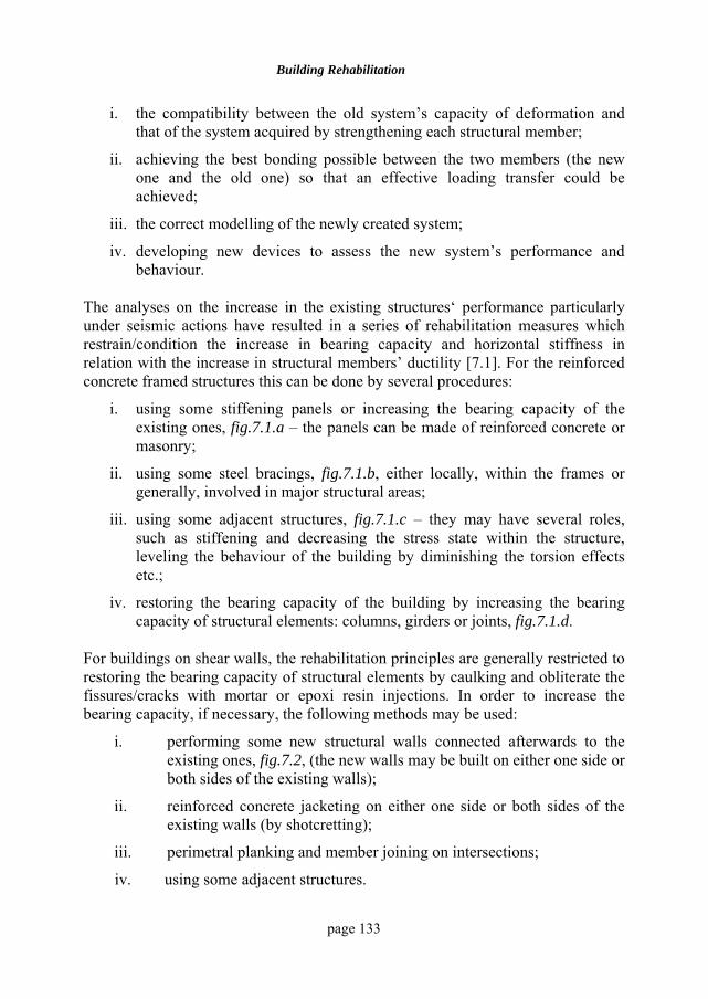
Building Rehabilitation
page 133
i. the compatibility between the old system’s capacity of deformation and that of the system acquired by strengthening each structural member;
ii. achieving the best bonding possible between the two members (the new one and the old one) so that an effective loading transfer could be achieved;
iii. the correct modelling of the newly created system;
iv. developing new devices to assess the new system’s performance and behaviour.
The analyses on the increase in the existing structures‘ performance particularly under seismic actions have resulted in a series of rehabilitation measures which restrain/condition the increase in bearing capacity and horizontal stiffness in relation with the increase in structural members’ ductility [7.1]. For the reinforced concrete framed structures this can be done by several procedures:
i. using some stiffening panels or increasing the bearing capacity of the existing ones, fig.7.1.a – the panels can be made of reinforced concrete or masonry;
ii. using some steel bracings, fig.7.1.b, either locally, within the frames or generally, involved in major structural areas;
iii. using some adjacent structures, fig.7.1.c – they may have several roles, such as stiffening and decreasing the stress state within the structure, leveling the behaviour of the building by diminishing the torsion effects etc.;
iv. restoring the bearing capacity of the building by increasing the bearing capacity of structural elements: columns, girders or joints, fig.7.1.d.
For buildings on shear walls, the rehabilitation principles are generally restricted to restoring the bearing capacity of structural elements by caulking and obliterate the fissures/cracks with mortar or epoxi resin injections. In order to increase the bearing capacity, if necessary, the following methods may be used:
i. performing some new structural walls connected afterwards to the existing ones, fig.7.2, (the new walls may be built on either one side or both sides of the existing walls);
ii. reinforced concrete jacketing on either one side or both sides of the existing walls (by shotcretting);
iii. perimetral planking and member joining on intersections;
iv. using some adjacent structures.
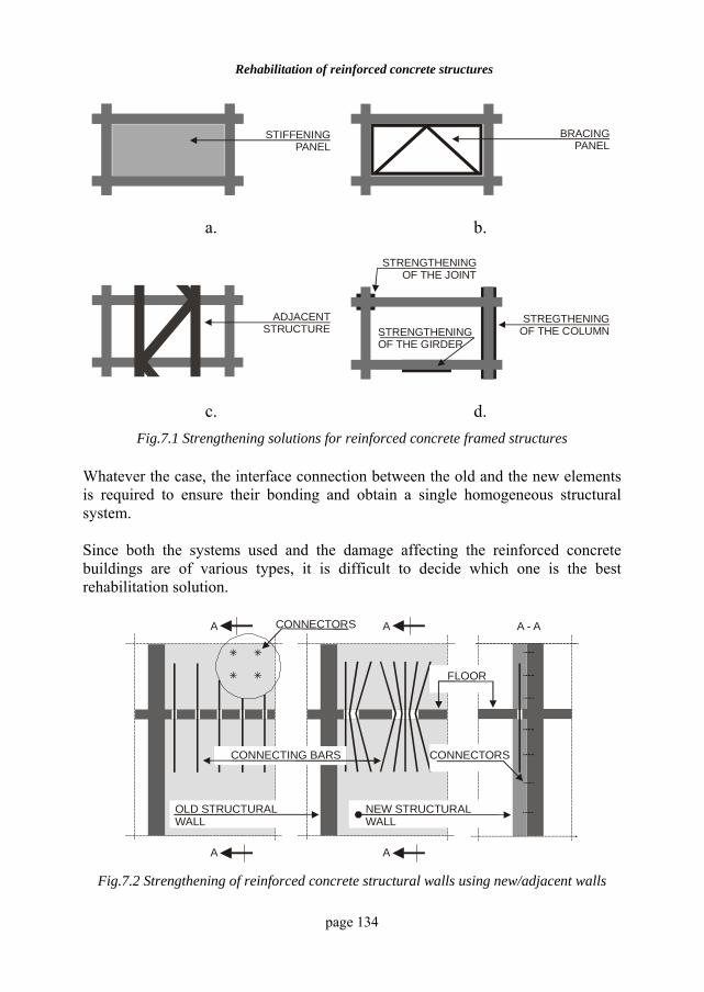
Rehabilitation of reinforced concrete structures
page 134
STIFFENINGPANEL
BRACINGPANEL
a. b.
ADJACENTSTRUCTURE
STRENGTHENINGOF THE JOINT
STREGTHENINGOF THE COLUMNSTRENGTHENING
OF THE GIRDER
c. d. Fig.7.1 Strengthening solutions for reinforced concrete framed structures
Whatever the case, the interface connection between the old and the new elements is required to ensure their bonding and obtain a single homogeneous structural system. Since both the systems used and the damage affecting the reinforced concrete buildings are of various types, it is difficult to decide which one is the best rehabilitation solution.
A
A
A - AA
A
CONNECTING BARS
OLD STRUCTURALWALL
NEW STRUCTURALWALL
++ ++
++ ++
CONNECTORS
CONNECTORS
FLOOR
Fig.7.2 Strengthening of reinforced concrete structural walls using new/adjacent walls
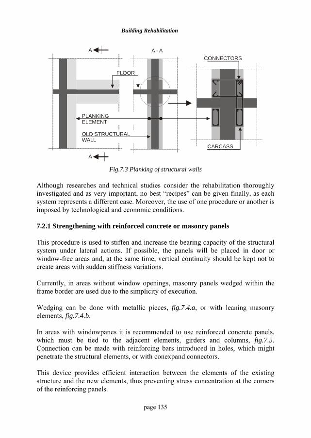
Building Rehabilitation
page 135
A
A
A - A
FLOOR
CONNECTORS
OLD STRUCTURAL WALL
PLANKINGELEMENT
CARCASS
Fig.7.3 Planking of structural walls
Although researches and technical studies consider the rehabilitation thoroughly investigated and as very important, no best “recipes” can be given finally, as each system represents a different case. Moreover, the use of one procedure or another is imposed by technological and economic conditions. 7.2.1 Strengthening with reinforced concrete or masonry panels This procedure is used to stiffen and increase the bearing capacity of the structural system under lateral actions. If possible, the panels will be placed in door or window-free areas and, at the same time, vertical continuity should be kept not to create areas with sudden stiffness variations. Currently, in areas without window openings, masonry panels wedged within the frame border are used due to the simplicity of execution. Wedging can be done with metallic pieces, fig.7.4.a, or with leaning masonry elements, fig.7.4.b. In areas with windowpanes it is recommended to use reinforced concrete panels, which must be tied to the adjacent elements, girders and columns, fig.7.5. Connection can be made with reinforcing bars introduced in holes, which might penetrate the structural elements, or with conexpand connectors. This device provides efficient interaction between the elements of the existing structure and the new elements, thus preventing stress concentration at the corners of the reinforcing panels.
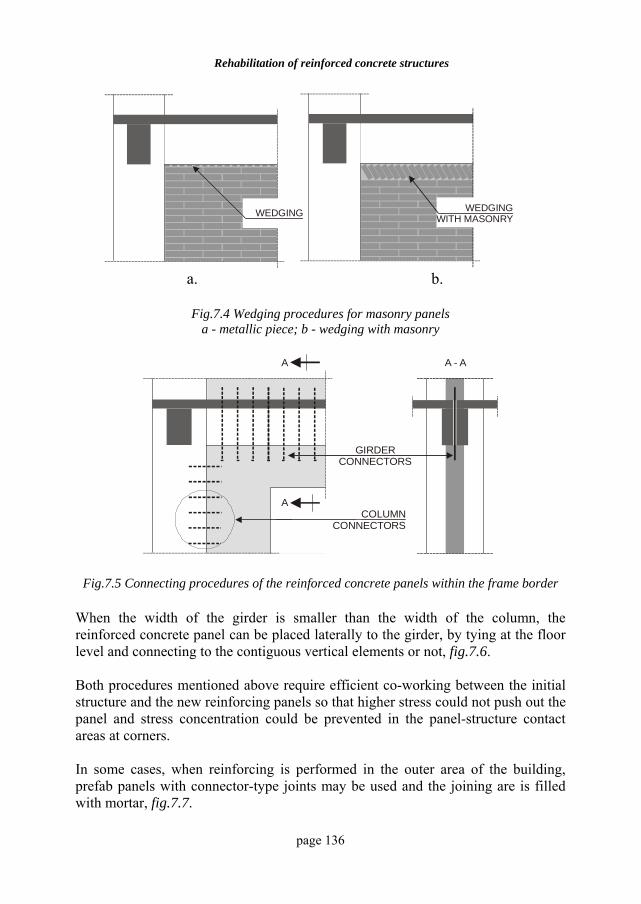
Rehabilitation of reinforced concrete structures
page 136
WEDGING WEDGINGWITH MASONRY
a. b.
Fig.7.4 Wedging procedures for masonry panels
a - metallic piece; b - wedging with masonry
GIRDERCONNECTORS
COLUMNCONNECTORS
A
A
A - A
Fig.7.5 Connecting procedures of the reinforced concrete panels within the frame border
When the width of the girder is smaller than the width of the column, the reinforced concrete panel can be placed laterally to the girder, by tying at the floor level and connecting to the contiguous vertical elements or not, fig.7.6. Both procedures mentioned above require efficient co-working between the initial structure and the new reinforcing panels so that higher stress could not push out the panel and stress concentration could be prevented in the panel-structure contact areas at corners. In some cases, when reinforcing is performed in the outer area of the building, prefab panels with connector-type joints may be used and the joining are is filled with mortar, fig.7.7.
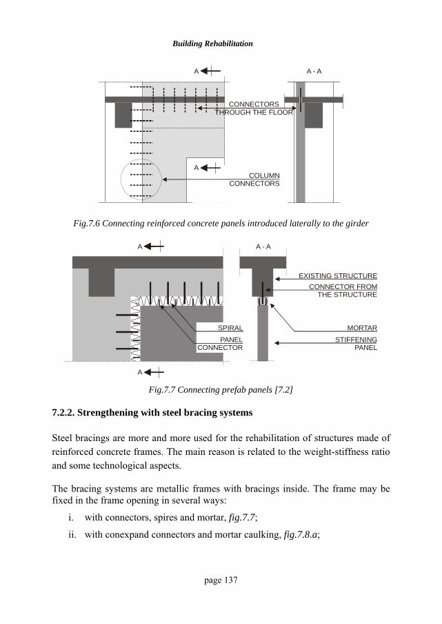
Building Rehabilitation
page 137
CONNECTORSTHROUGH THE FLOOR
COLUMNCONNECTORS
A
A
A - A
Fig.7.6 Connecting reinforced concrete panels introduced laterally to the girder
A
A
A - A
SPIRAL
PANELCONNECTOR
EXISTING STRUCTURECONNECTOR FROM
THE STRUCTURE
MORTAR
STIFFENINGPANEL
Fig.7.7 Connecting prefab panels [7.2]
7.2.2. Strengthening with steel bracing systems Steel bracings are more and more used for the rehabilitation of structures made of reinforced concrete frames. The main reason is related to the weight-stiffness ratio and some technological aspects. The bracing systems are metallic frames with bracings inside. The frame may be fixed in the frame opening in several ways:
i. with connectors, spires and mortar, fig.7.7;
ii. with conexpand connectors and mortar caulking, fig.7.8.a;
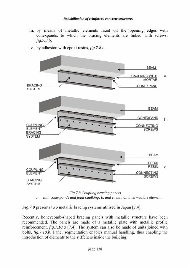
Rehabilitation of reinforced concrete structures
page 138
iii. by means of metallic elements fixed on the opening edges with conexpands, to which the bracing elements are linked with screws, fig.7.8.b,
iv. by adhesion with epoxi resins, fig.7.8.c.
a.
b.
c.
Fig.7.8 Coupling bracing panels a. with conexpands and joint caulking; b. and c. with an intermediate element
Fig.7.9 presents two metallic bracing systems utilised in Japan [7.4]. Recently, honeycomb-shaped bracing panels with metallic structure have been recommended. The panels are made of a metallic plate with metallic profile reinforcement, fig.7.10.a [7.4]. The system can also be made of units joined with bolts, fig.7.10.b. Panel segmentation enables manual handling, thus enabling the introduction of elements to the stiffeners inside the building.
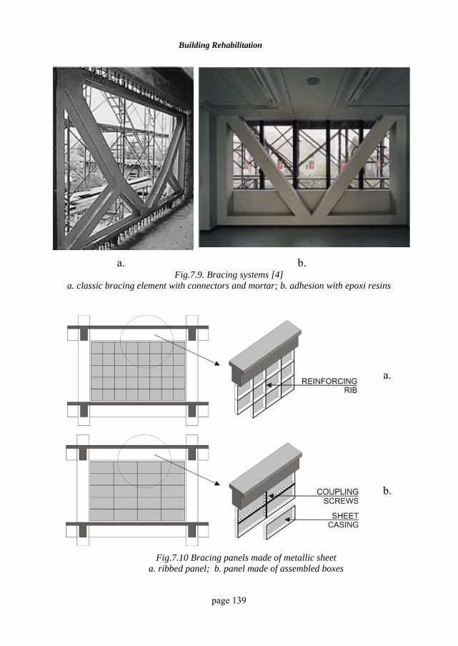
Building Rehabilitation
page 139
a. b. Fig.7.9. Bracing systems [4]
a. classic bracing element with connectors and mortar; b. adhesion with epoxi resins
a.
b.
Fig.7.10 Bracing panels made of metallic sheet a. ribbed panel; b. panel made of assembled boxes
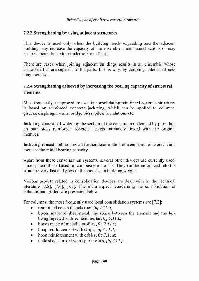
Rehabilitation of reinforced concrete structures
page 140
7.2.3 Strengthening by using adjacent structures This device is used only when the building needs expanding and the adjacent building may increase the capacity of the ensemble under lateral actions or may ensure a better behaviour under torsion effects. There are cases when joining adjacent buildings results in an ensemble whose characteristics are superior to the parts. In this way, by coupling, lateral stiffness may increase. 7.2.4 Strengthening achieved by increasing the bearing capacity of structural elements Most frequently, the procedure used in consolidating reinforced concrete structures is based on reinforced concrete jacketing, which can be applied to columns, girders, diaphragm walls, bridge piers, piles, foundations etc. Jacketing consists of widening the section of the construction element by providing on both sides reinforced concrete jackets intimately linked with the original member. Jacketing is used both to prevent further deterioration of a construction element and increase the initial bearing capacity. Apart from these consolidation systems, several other devices are currently used, among them those based on composite materials. They can be introduced into the structure very fast and prevent the increase in building weight. Various aspects related to consolidation devices are dealt with in the technical literature [7.5], [7.6], [7.7]. The main aspects concerning the consolidation of columns and girders are presented below. For columns, the most frequently used local consolidation systems are [7.2]:
• reinforced concrete jacketing, fig.7.11.a; • boxes made of sheet-metal, the space between the element and the box
being injected with cement mortar, fig.7.11.b; • boxes made of metallic profiles, fig.7.11.c; • hoop reinforcement with strips, fig.7.11.d; • hoop reinforcement with cables, fig.7.11.e; • table sheets linked with epoxi resins, fig.7.11.f.
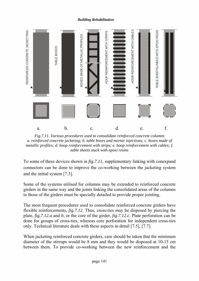
Building Rehabilitation
page 141
BOXE
S M
ADE
OF
MET
ALLI
C P
RO
FILE
S
REI
NFO
RCED
CO
NCR
ETE
JAC
KETT
ING
HO
OP
REI
NFO
RCEM
ENT
WIT
H S
TRIP
S
TABL
E SH
EETS
LINK
ED
WIT
H E
POXI
RES
IN
HO
OP
REI
NFO
RCEM
ENT
WIT
H C
ABLE
S
TABL
E BO
XES
a. b. c. d. e. f.
Fig.7.11. Various procedures used to consolidate reinforced concrete columns a. reinforced concrete jacketing; b. table boxes and mortar injections; c. boxes made of
metallic profiles; d. hoop reinforcement with strips; e. hoop reinforcement with cables; f. table sheets stuck with epoxi resins
To some of these devices shown in fig.7.11, supplementary linking with conexpand connectors can be done to improve the co-working between the jacketing system and the initial system [7.3]. Some of the systems utilised for columns may be extended to reinforced concrete girders in the same way and the joints linking the consolidated areas of the columns to those of the girders must be specially detailed to provide proper jointing. The most frequent procedures used to consolidate reinforced concrete girders have flexible reinforcements, fig.7.12. Thus, cross-ties may be disposed by piercing the plate, fig.7.12.a and b, or the core of the girder, fig.7.12.c. Plate perforation can be done for groups of cross-ties, whereas core perforation for independent cross-ties only. Technical literature deals with these aspects in detail [7.5], [7.7]. When jacketing reinforced concrete girders, care should be taken that the minimum diameter of the stirrups would be 8 mm and they would be disposed at 10-15 cm between them. To provide co-working between the new reinforcement and the
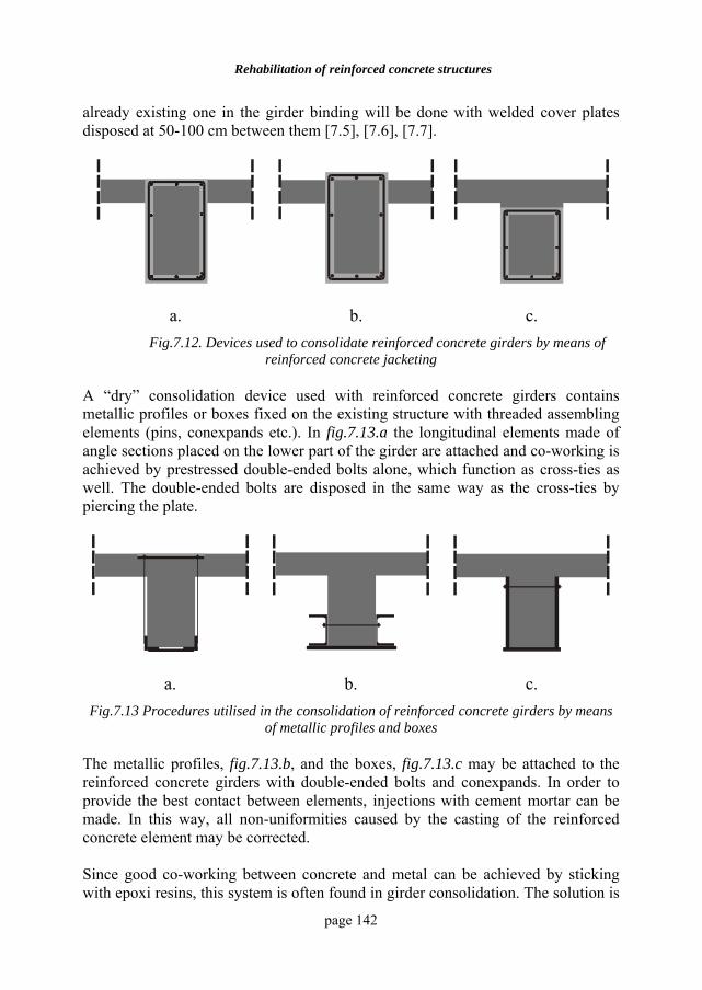
Rehabilitation of reinforced concrete structures
page 142
already existing one in the girder binding will be done with welded cover plates disposed at 50-100 cm between them [7.5], [7.6], [7.7].
a. b. c. Fig.7.12. Devices used to consolidate reinforced concrete girders by means of
reinforced concrete jacketing A “dry” consolidation device used with reinforced concrete girders contains metallic profiles or boxes fixed on the existing structure with threaded assembling elements (pins, conexpands etc.). In fig.7.13.a the longitudinal elements made of angle sections placed on the lower part of the girder are attached and co-working is achieved by prestressed double-ended bolts alone, which function as cross-ties as well. The double-ended bolts are disposed in the same way as the cross-ties by piercing the plate.
a. b. c. Fig.7.13 Procedures utilised in the consolidation of reinforced concrete girders by means
of metallic profiles and boxes The metallic profiles, fig.7.13.b, and the boxes, fig.7.13.c may be attached to the reinforced concrete girders with double-ended bolts and conexpands. In order to provide the best contact between elements, injections with cement mortar can be made. In this way, all non-uniformities caused by the casting of the reinforced concrete element may be corrected. Since good co-working between concrete and metal can be achieved by sticking with epoxi resins, this system is often found in girder consolidation. The solution is
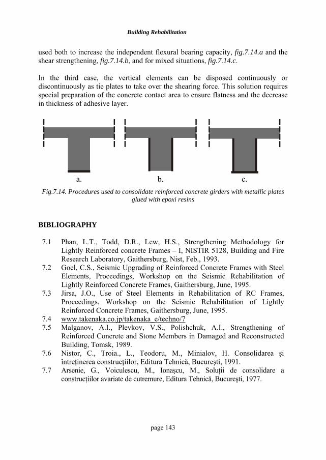
Building Rehabilitation
page 143
used both to increase the independent flexural bearing capacity, fig.7.14.a and the shear strengthening, fig.7.14.b, and for mixed situations, fig.7.14.c. In the third case, the vertical elements can be disposed continuously or discontinuously as tie plates to take over the shearing force. This solution requires special preparation of the concrete contact area to ensure flatness and the decrease in thickness of adhesive layer.
a. b. c.
Fig.7.14. Procedures used to consolidate reinforced concrete girders with metallic plates glued with epoxi resins
BIBLIOGRAPHY 7.1 Phan, L.T., Todd, D.R., Lew, H.S., Strengthening Methodology for
Lightly Reinforced concrete Frames – I, NISTIR 5128, Building and Fire Research Laboratory, Gaithersburg, Nist, Feb., 1993.
7.2 Goel, C.S., Seismic Upgrading of Reinforced Concrete Frames with Steel Elements, Proceedings, Workshop on the Seismic Rehabilitation of Lightly Reinforced Concrete Frames, Gaithersburg, June, 1995.
7.3 Jirsa, J.O., Use of Steel Elements in Rehabilitation of RC Frames, Proceedings, Workshop on the Seismic Rehabilitation of Lightly Reinforced Concrete Frames, Gaithersburg, June, 1995.
7.4 www.takenaka.co.jp/takenaka_e/techno/7 7.5 Malganov, A.I., Plevkov, V.S., Polishchuk, A.I., Strengthening of
Reinforced Concrete and Stone Members in Damaged and Reconstructed Building, Tomsk, 1989.
7.6 Nistor, C., Troia., L., Teodoru, M., Minialov, H. Consolidarea şi întreţinerea construcţiilor, Editura Tehnică, Bucureşti, 1991.
7.7 Arsenie, G., Voiculescu, M., Ionaşcu, M., Soluţii de consolidare a construcţiilor avariate de cutremure, Editura Tehnică, Bucureşti, 1977.
page 144
8 NEW SYSTEMS OF STRUCTURAL
REHABILITATION TO EARTHQUAKES 8.1 GENERAL ASPECTS During their life, buildings undergo numerous damages due to various causes, which were widely presented in the paragraph 1.2. Among them, earthquake remains the most important, resulting in significant degradations in structures. Earthquakes can even lead to the collapse of structures if the design rules for earthquake resistance of structures are not met. In this case the design engineer must pay attention not only to the accurate conception, design and execution of structures but to consider some new rehabilitation procedures for damaged structures. The economical evaluations showed that damaged structures repairing and rehabilitation imply significant costs that could be up to 30% of the cost of a new similar building [8.1] and which can not always ensure safety during struture’s life. The structural rehabilitation is a complex task, more difficult than the design and execution of a new building. The conception and execution of the rehabilitation projects imply technical experts with important technical knowledge and practical experience. Besides the classical rehabilitation procedures, in the last 20 years a series of new seismic isolation procedures were outlined and adopted widely in pracice, such as:
i. base isolation;
ii. increase in energy dissipation capacity. 8.2 BASE ISOLATION The limitation of the energy induced in structures by earthquakes can be carried out by base isolation. Base isolation mainly consists of uncoupling the foundation from the structure. Thus, it results in a sliding surface which allows the free motion of
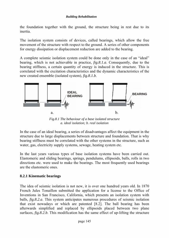
Building Rehabilitation
page 145
the foundation together with the ground, the structure being in rest due to its inertia. The isolation system consists of devices, called bearings, which allow the free movement of the structure with respect to the ground. A series of other components for energy dissipation or displacement reduction are added to the bearing. A complete seismic isolation system could be done only in the case of an “ideal” bearing, which is not achievable in practice, fig.8.1.a. Consequently, due to the bearing stiffness, a certain quantity of energy is induced in the structure. This is correlated with the excitation characteristics and the dynamic characteristics of the new created ensemble (isolated system), fig.8.1.b.
IDEAL BEARING BEARING
a. b.
Fig.8.1 The behaviour of a base isolated structure a. ideal isolation; b. real isolation
In the case of an ideal bearing, a series of disadvantages affect the equipment in the structure due to large displacements between structure and foundation. That is why bearing stiffness must be correlated with the other systems in the structure, such as water, gas, electricity supply systems, sewage, heating system etc. In the last years various types of base isolation systems have been carried out. Elastomeric and sliding bearings, springs, pendulums, ellipsoids, balls, rolls in two directions etc. were used to make the bearings. The most frequently used bearings are the elastomeric ones. 8.2.1 Kinematic bearings The idea of seismic isolation is not new, it is over one hundred years old. In 1870 French Jules Tonaillon submitted the application for a license to the Office of Inventions in San Francisco, California, which presents an isolation system with balls, fig.8.2.a. This system anticipates numerous procedures of seismic isolation that exist nowadays or which are patented [8.2]. The ball bearing has been afterwards simplified and replaced by ellipsoids placed between two plane surfaces, fig.8.2.b. This modification has the same effect of up-lifting the structure
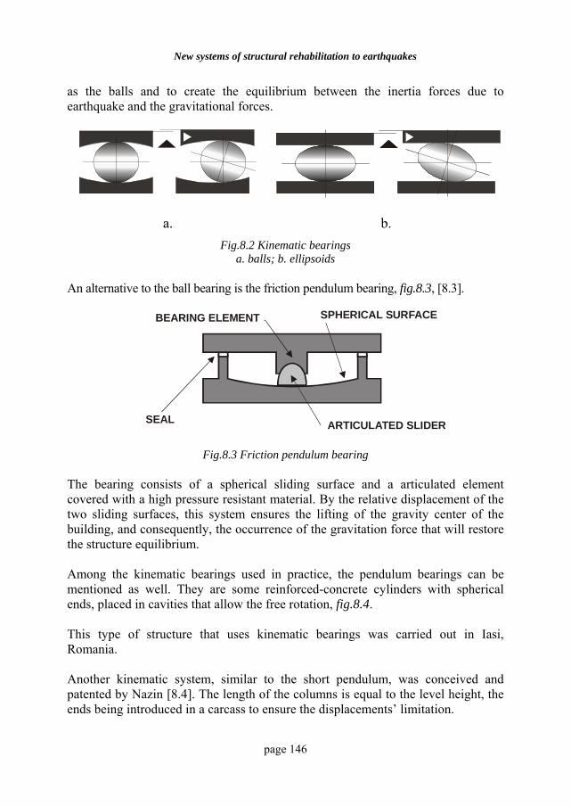
New systems of structural rehabilitation to earthquakes
page 146
as the balls and to create the equilibrium between the inertia forces due to earthquake and the gravitational forces.
a. b. Fig.8.2 Kinematic bearings
a. balls; b. ellipsoids An alternative to the ball bearing is the friction pendulum bearing, fig.8.3, [8.3].
SUPRAFATA SFERICAELEMENT DE SUSTINERE
ELEMENT DE ETANSARE GLISOR
SPHERICAL SURFACEBEARING ELEMENT
ARTICULATED SLIDERSEAL
Fig.8.3 Friction pendulum bearing The bearing consists of a spherical sliding surface and a articulated element covered with a high pressure resistant material. By the relative displacement of the two sliding surfaces, this system ensures the lifting of the gravity center of the building, and consequently, the occurrence of the gravitation force that will restore the structure equilibrium. Among the kinematic bearings used in practice, the pendulum bearings can be mentioned as well. They are some reinforced-concrete cylinders with spherical ends, placed in cavities that allow the free rotation, fig.8.4. This type of structure that uses kinematic bearings was carried out in Iasi, Romania. Another kinematic system, similar to the short pendulum, was conceived and patented by Nazin [8.4]. The length of the columns is equal to the level height, the ends being introduced in a carcass to ensure the displacements’ limitation.
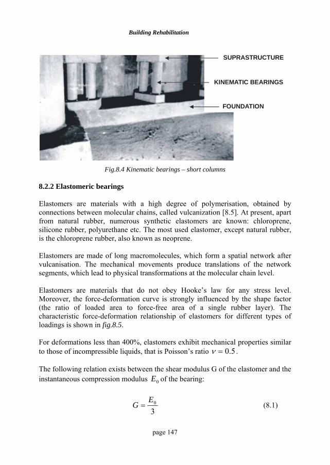
Building Rehabilitation
page 147
SUPRASTRUCTURE
KINEMATIC BEARINGS
FOUNDATION
Fig.8.4 Kinematic bearings – short columns
8.2.2 Elastomeric bearings Elastomers are materials with a high degree of polymerisation, obtained by connections between molecular chains, called vulcanization [8.5]. At present, apart from natural rubber, numerous synthetic elastomers are known: chloroprene, silicone rubber, polyurethane etc. The most used elastomer, except natural rubber, is the chloroprene rubber, also known as neoprene. Elastomers are made of long macromolecules, which form a spatial network after vulcanisation. The mechanical movements produce translations of the network segments, which lead to physical transformations at the molecular chain level. Elastomers are materials that do not obey Hooke’s law for any stress level. Moreover, the force-deformation curve is strongly influenced by the shape factor (the ratio of loaded area to force-free area of a single rubber layer). The characteristic force-deformation relationship of elastomers for different types of loadings is shown in fig.8.5. For deformations less than 400%, elastomers exhibit mechanical properties similar to those of incompressible liquids, that is Poisson’s ratio 5.0=ν . The following relation exists between the shear modulus G of the elastomer and the instantaneous compression modulus 0E of the bearing:
30E
G = (8.1)
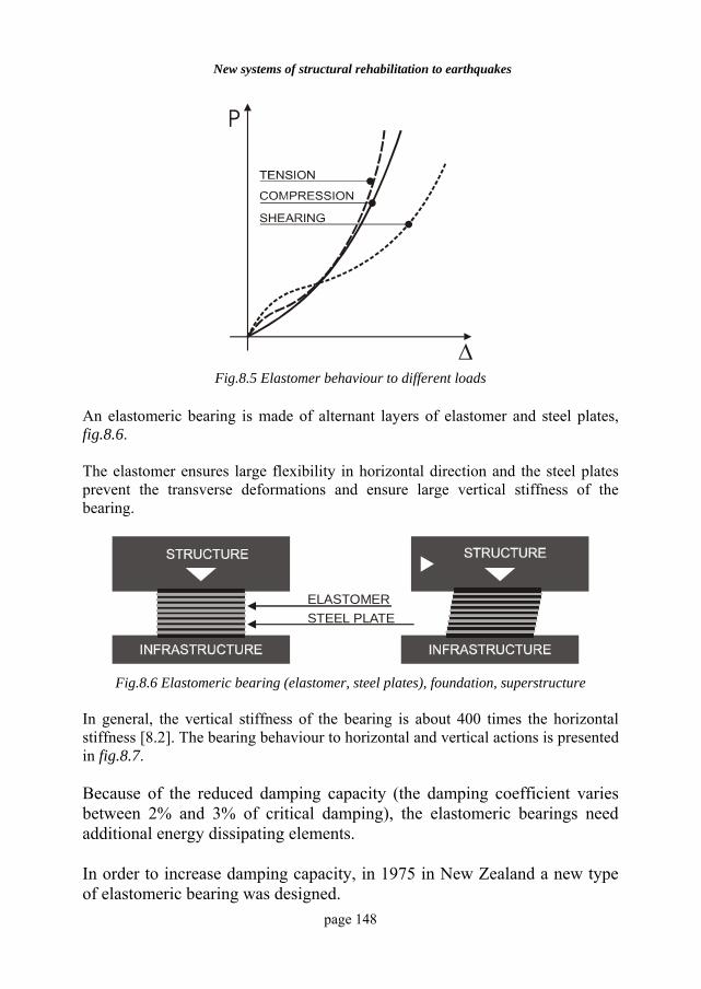
New systems of structural rehabilitation to earthquakes
page 148
P
∆ Fig.8.5 Elastomer behaviour to different loads
An elastomeric bearing is made of alternant layers of elastomer and steel plates, fig.8.6. The elastomer ensures large flexibility in horizontal direction and the steel plates prevent the transverse deformations and ensure large vertical stiffness of the bearing.
ELASTOMER STEEL PLATE
Fig.8.6 Elastomeric bearing (elastomer, steel plates), foundation, superstructure
In general, the vertical stiffness of the bearing is about 400 times the horizontal stiffness [8.2]. The bearing behaviour to horizontal and vertical actions is presented in fig.8.7. Because of the reduced damping capacity (the damping coefficient varies between 2% and 3% of critical damping), the elastomeric bearings need additional energy dissipating elements. In order to increase damping capacity, in 1975 in New Zealand a new type of elastomeric bearing was designed.
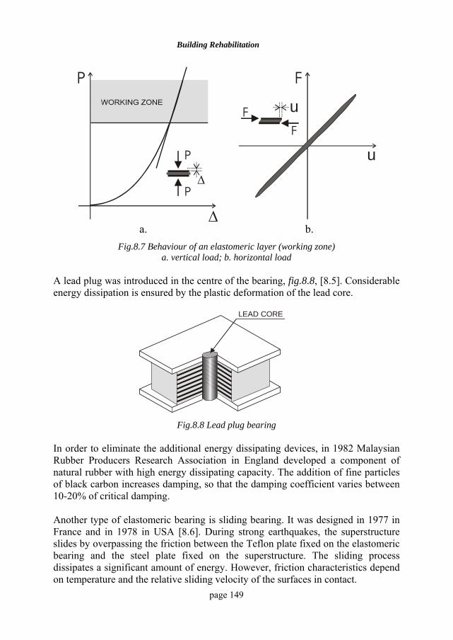
Building Rehabilitation
page 149
P
∆
P
P
∆
F
uF
F u
a. b.
Fig.8.7 Behaviour of an elastomeric layer (working zone) a. vertical load; b. horizontal load
A lead plug was introduced in the centre of the bearing, fig.8.8, [8.5]. Considerable energy dissipation is ensured by the plastic deformation of the lead core.
LEAD CORE
Fig.8.8 Lead plug bearing
In order to eliminate the additional energy dissipating devices, in 1982 Malaysian Rubber Producers Research Association in England developed a component of natural rubber with high energy dissipating capacity. The addition of fine particles of black carbon increases damping, so that the damping coefficient varies between 10-20% of critical damping. Another type of elastomeric bearing is sliding bearing. It was designed in 1977 in France and in 1978 in USA [8.6]. During strong earthquakes, the superstructure slides by overpassing the friction between the Teflon plate fixed on the elastomeric bearing and the steel plate fixed on the superstructure. The sliding process dissipates a significant amount of energy. However, friction characteristics depend on temperature and the relative sliding velocity of the surfaces in contact.
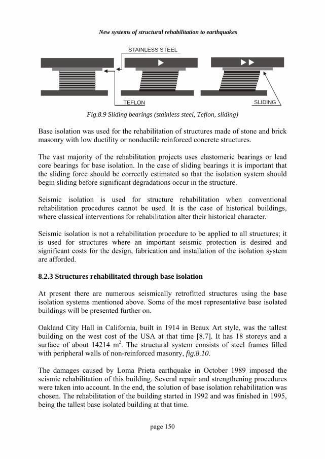
New systems of structural rehabilitation to earthquakes
page 150
TEFLON
STAINLESS STEEL
SLIDING Fig.8.9 Sliding bearings (stainless steel, Teflon, sliding)
Base isolation was used for the rehabilitation of structures made of stone and brick masonry with low ductility or nonductile reinforced concrete structures. The vast majority of the rehabilitation projects uses elastomeric bearings or lead core bearings for base isolation. In the case of sliding bearings it is important that the sliding force should be correctly estimated so that the isolation system should begin sliding before significant degradations occur in the structure. Seismic isolation is used for structure rehabilitation when conventional rehabilitation procedures cannot be used. It is the case of historical buildings, where classical interventions for rehabilitation alter their historical character. Seismic isolation is not a rehabilitation procedure to be applied to all structures; it is used for structures where an important seismic protection is desired and significant costs for the design, fabrication and installation of the isolation system are afforded. 8.2.3 Structures rehabilitated through base isolation At present there are numerous seismically retrofitted structures using the base isolation systems mentioned above. Some of the most representative base isolated buildings will be presented further on. Oakland City Hall in California, built in 1914 in Beaux Art style, was the tallest building on the west cost of the USA at that time [8.7]. It has 18 storeys and a surface of about 14214 m2. The structural system consists of steel frames filled with peripheral walls of non-reinforced masonry, fig.8.10. The damages caused by Loma Prieta earthquake in October 1989 imposed the seismic rehabilitation of this building. Several repair and strengthening procedures were taken into account. In the end, the solution of base isolation rehabilitation was chosen. The rehabilitation of the building started in 1992 and was finished in 1995, being the tallest base isolated building at that time.
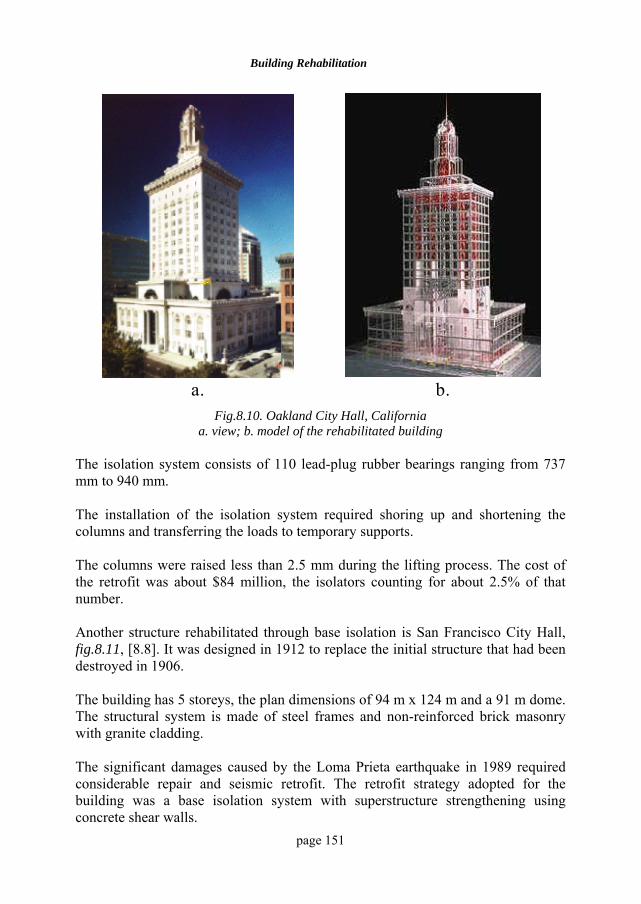
Building Rehabilitation
page 151
a. b.
Fig.8.10. Oakland City Hall, California a. view; b. model of the rehabilitated building
The isolation system consists of 110 lead-plug rubber bearings ranging from 737 mm to 940 mm. The installation of the isolation system required shoring up and shortening the columns and transferring the loads to temporary supports. The columns were raised less than 2.5 mm during the lifting process. The cost of the retrofit was about $84 million, the isolators counting for about 2.5% of that number. Another structure rehabilitated through base isolation is San Francisco City Hall, fig.8.11, [8.8]. It was designed in 1912 to replace the initial structure that had been destroyed in 1906. The building has 5 storeys, the plan dimensions of 94 m x 124 m and a 91 m dome. The structural system is made of steel frames and non-reinforced brick masonry with granite cladding. The significant damages caused by the Loma Prieta earthquake in 1989 required considerable repair and seismic retrofit. The retrofit strategy adopted for the building was a base isolation system with superstructure strengthening using concrete shear walls.
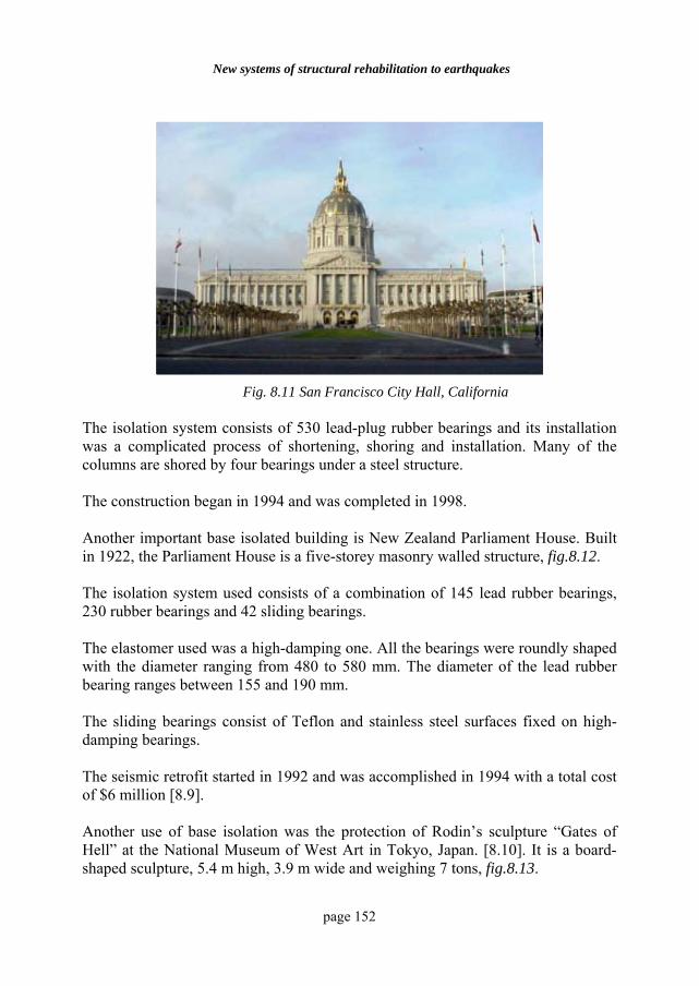
New systems of structural rehabilitation to earthquakes
page 152
Fig. 8.11 San Francisco City Hall, California
The isolation system consists of 530 lead-plug rubber bearings and its installation was a complicated process of shortening, shoring and installation. Many of the columns are shored by four bearings under a steel structure. The construction began in 1994 and was completed in 1998. Another important base isolated building is New Zealand Parliament House. Built in 1922, the Parliament House is a five-storey masonry walled structure, fig.8.12. The isolation system used consists of a combination of 145 lead rubber bearings, 230 rubber bearings and 42 sliding bearings. The elastomer used was a high-damping one. All the bearings were roundly shaped with the diameter ranging from 480 to 580 mm. The diameter of the lead rubber bearing ranges between 155 and 190 mm. The sliding bearings consist of Teflon and stainless steel surfaces fixed on high-damping bearings. The seismic retrofit started in 1992 and was accomplished in 1994 with a total cost of $6 million [8.9]. Another use of base isolation was the protection of Rodin’s sculpture “Gates of Hell” at the National Museum of West Art in Tokyo, Japan. [8.10]. It is a board-shaped sculpture, 5.4 m high, 3.9 m wide and weighing 7 tons, fig.8.13.
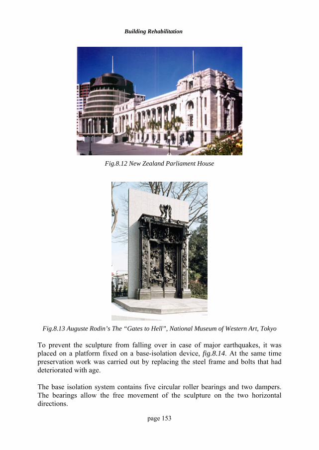
Building Rehabilitation
page 153
Fig.8.12 New Zealand Parliament House
Fig.8.13 Auguste Rodin’s The “Gates to Hell”, National Museum of Western Art, Tokyo
To prevent the sculpture from falling over in case of major earthquakes, it was placed on a platform fixed on a base-isolation device, fig.8.14. At the same time preservation work was carried out by replacing the steel frame and bolts that had deteriorated with age. The base isolation system contains five circular roller bearings and two dampers. The bearings allow the free movement of the sculpture on the two horizontal directions.
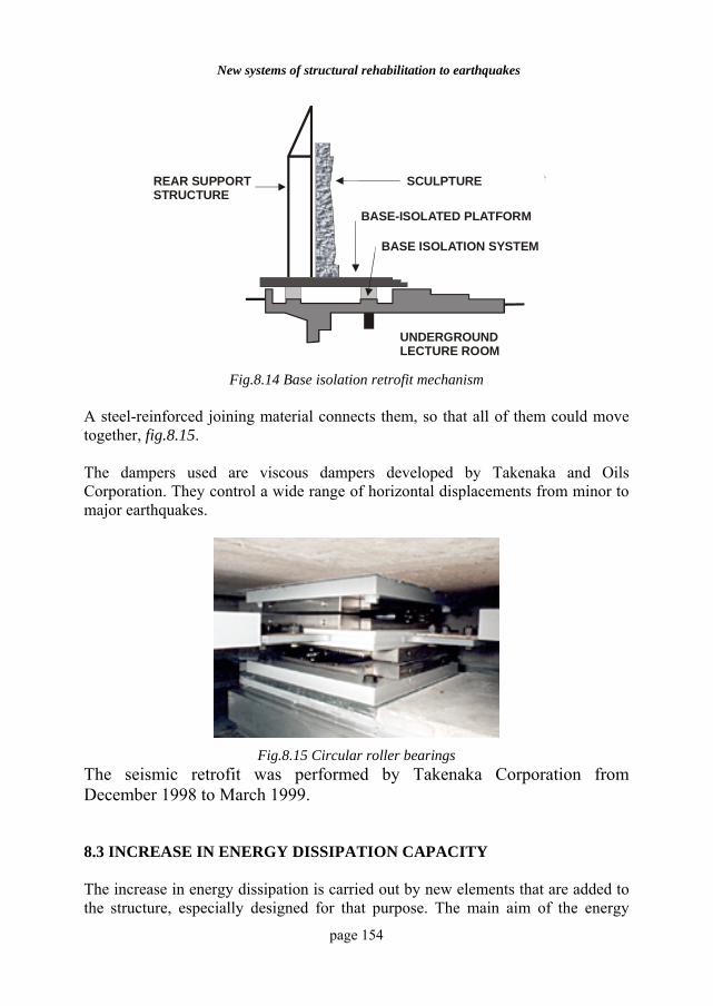
New systems of structural rehabilitation to earthquakes
page 154
STRUCTURA DE SUSTINERE A LUCRARII
SCULPTURA
PLATFORMA CU BAZA IZOLATA
SISTEM DE IZOLARE A BAZEI
SALA DE LECTURA
REAR SUPPORT STRUCTURE
SCULPTURE
BASE-ISOLATED PLATFORM
BASE ISOLATION SYSTEM
UNDERGROUNDLECTURE ROOM
Fig.8.14 Base isolation retrofit mechanism A steel-reinforced joining material connects them, so that all of them could move together, fig.8.15. The dampers used are viscous dampers developed by Takenaka and Oils Corporation. They control a wide range of horizontal displacements from minor to major earthquakes.
Fig.8.15 Circular roller bearings
The seismic retrofit was performed by Takenaka Corporation from December 1998 to March 1999. 8.3 INCREASE IN ENERGY DISSIPATION CAPACITY The increase in energy dissipation is carried out by new elements that are added to the structure, especially designed for that purpose. The main aim of the energy
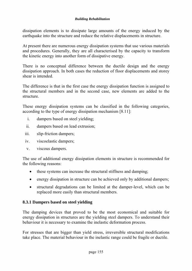
Building Rehabilitation
page 155
dissipation elements is to dissipate large amounts of the energy induced by the earthquake into the structure and reduce the relative displacements in structure. At present there are numerous energy dissipation systems that use various materials and procedures. Generally, they are all characterised by the capacity to transform the kinetic energy into another form of dissipative energy. There is no conceptual difference between the ductile design and the energy dissipation approach. In both cases the reduction of floor displacements and storey shear is intended. The difference is that in the first case the energy dissipation function is assigned to the structural members and in the second case, new elements are added to the structure. These energy dissipation systems can be classified in the following categories, according to the type of energy dissipation mechanism [8.11]:
i. dampers based on steel yielding;
ii. dampers based on lead extrusion;
iii. slip-friction dampers;
iv. viscoelastic dampers;
v. viscous dampers. The use of additional energy dissipation elements in structure is recommended for the following reasons:
• these systems can increase the structural stiffness and damping;
• energy dissipation in structure can be achieved only by additional dampers;
• structural degradations can be limited at the damper-level, which can be replaced more easily than structural members.
8.3.1 Dampers based on steel yielding The damping devices that proved to be the most economical and suitable for energy dissipation in structures are the yielding steel dampers. To understand their behaviour it is necessary to examine the inelastic deformation process. For stresses that are bigger than yield stress, irreversible structural modifications take place. The material behaviour in the inelastic range could be fragile or ductile.
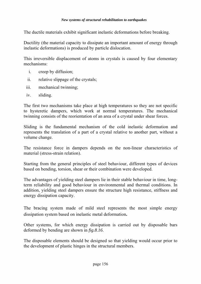
New systems of structural rehabilitation to earthquakes
page 156
The ductile materials exhibit significant inelastic deformations before breaking. Ductility (the material capacity to dissipate an important amount of energy through inelastic deformations) is produced by particle dislocation. This irreversible displacement of atoms in crystals is caused by four elementary mechanisms:
i. creep by diffusion;
ii. relative slippage of the crystals;
iii. mechanical twinning;
iv. sliding. The first two mechanisms take place at high temperatures so they are not specific to hysteretic dampers, which work at normal temperatures. The mechanical twinning consists of the reorientation of an area of a crystal under shear forces. Sliding is the fundamental mechanism of the cold inelastic deformation and represents the translation of a part of a crystal relative to another part, without a volume change. The resistance force in dampers depends on the non-linear characteristics of material (stress-strain relation). Starting from the general principles of steel behaviour, different types of devices based on bending, torsion, shear or their combination were developed. The advantages of yielding steel dampers lie in their stable behaviour in time, long-term reliability and good behaviour in environmental and thermal conditions. In addition, yielding steel dampers ensure the structure high resistance, stiffness and energy dissipation capacity. The bracing system made of mild steel represents the most simple energy dissipation system based on inelastic metal deformation. Other systems, for which energy dissipation is carried out by disposable bars deformed by bending are shown in fig.8.16. The disposable elements should be designed so that yielding would occur prior to the development of plastic hinges in the structural members.
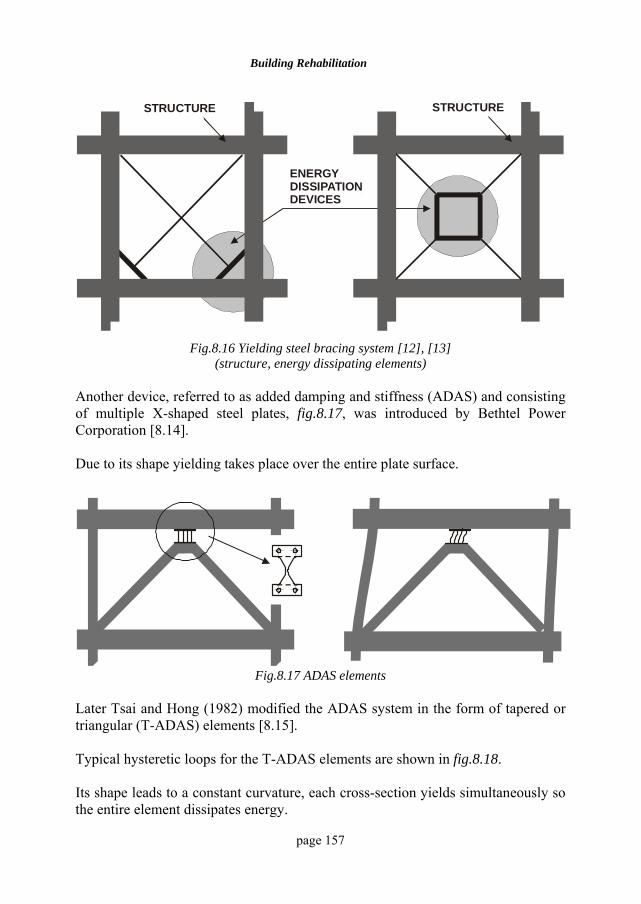
Building Rehabilitation
page 157
ELEMENTE DISIPATOARE DE ENERGIE
STRUCTURA STRUCTURASTRUCTURE STRUCTURE
ENERGY DISSIPATION DEVICES
Fig.8.16 Yielding steel bracing system [12], [13]
(structure, energy dissipating elements) Another device, referred to as added damping and stiffness (ADAS) and consisting of multiple X-shaped steel plates, fig.8.17, was introduced by Bethtel Power Corporation [8.14]. Due to its shape yielding takes place over the entire plate surface.
Fig.8.17 ADAS elements Later Tsai and Hong (1982) modified the ADAS system in the form of tapered or triangular (T-ADAS) elements [8.15]. Typical hysteretic loops for the T-ADAS elements are shown in fig.8.18. Its shape leads to a constant curvature, each cross-section yields simultaneously so the entire element dissipates energy.
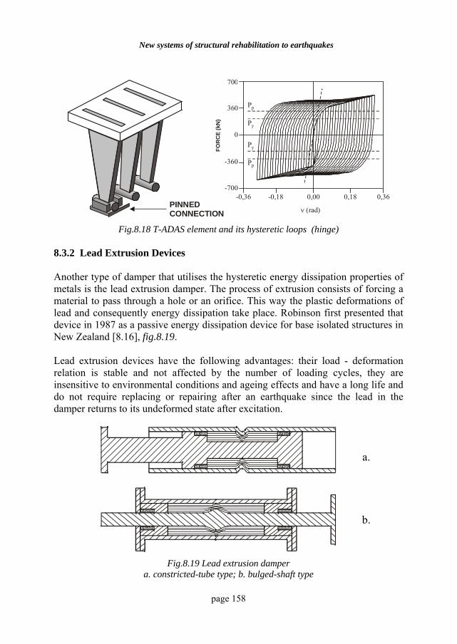
New systems of structural rehabilitation to earthquakes
page 158
ARTICULATIE
360
-360
-0,36 -0,18 0,00 0,18 0,36
Forta
(KN
)ν (rad)
0
700
Pp
Pp
Py
Py
-700
PINNED CONNECTION
FOR
CE
(kN
)
Fig.8.18 T-ADAS element and its hysteretic loops (hinge) 8.3.2 Lead Extrusion Devices Another type of damper that utilises the hysteretic energy dissipation properties of metals is the lead extrusion damper. The process of extrusion consists of forcing a material to pass through a hole or an orifice. This way the plastic deformations of lead and consequently energy dissipation take place. Robinson first presented that device in 1987 as a passive energy dissipation device for base isolated structures in New Zealand [8.16], fig.8.19. Lead extrusion devices have the following advantages: their load - deformation relation is stable and not affected by the number of loading cycles, they are insensitive to environmental conditions and ageing effects and have a long life and do not require replacing or repairing after an earthquake since the lead in the damper returns to its undeformed state after excitation.
a.
b.
Fig.8.19 Lead extrusion damper a. constricted-tube type; b. bulged-shaft type
Building Rehabilitation
page 159
8.3.3 Friction dampers In the last years a variety of friction devices has been proposed and developed for energy dissipation in structures. Most of these devices generate rectangular hysteretic loops, which indicate that the behaviour of friction dampers is similar to that of Coulomb friction. Generally, these devices have good performance characteristics, their behaviour being relatively less affected by load frequency, the number of load cycles or variations in temperature. These devices have high resistance to fatigue, as well, and differ in their mechanical complexity and in the material used for the sliding surfaces. In 1993 Gregorian and Popov proposed a friction device that allows the slip in slotted bolted connections [8.17]. The connection consists of two outer steel plates, a central slotted gusset plate and two shims fastened to the outer plates. The sliding interface consisted of brass and steel. In this type of connection the brass shims were scratched whereas the steel plates remained undamaged. The hysteretic loops are rectangular and stable after a large number of cycles compared to steel-to-steel interface, where evidence of a heavy abrasive wear was noticed. Flour Daniel Inc. has developed a friction device called Energy Dissipating Restraint [8.18]. The device consists of a cylinder, internal springs, compression wedges, friction wedges and stops. The Energy Dissipating Restraint mechanism consists of sliding friction through a range of motions with a stop at the ends of the cylinder. The Energy Dissipating Restraint is the only friction device that generates non-rectangular hysteresis loops and the slip load is proportional to the displacement. In contrast to other frictional devices that exhibit rectangular hysteresis loop, these devices are activated even by small excitations. The device has self-centering capabilities, which reduce permanent offsets when the structure deforms beyond the elastic range. Friction devices have difficulty in maintaining their properties over prolonged time intervals because the metallic interfaces are susceptible to corrosion, normal loads on the sliding interface cannot be reliably maintained and some relaxation should be expected over time and permanent offsets may occur after an earthquake.
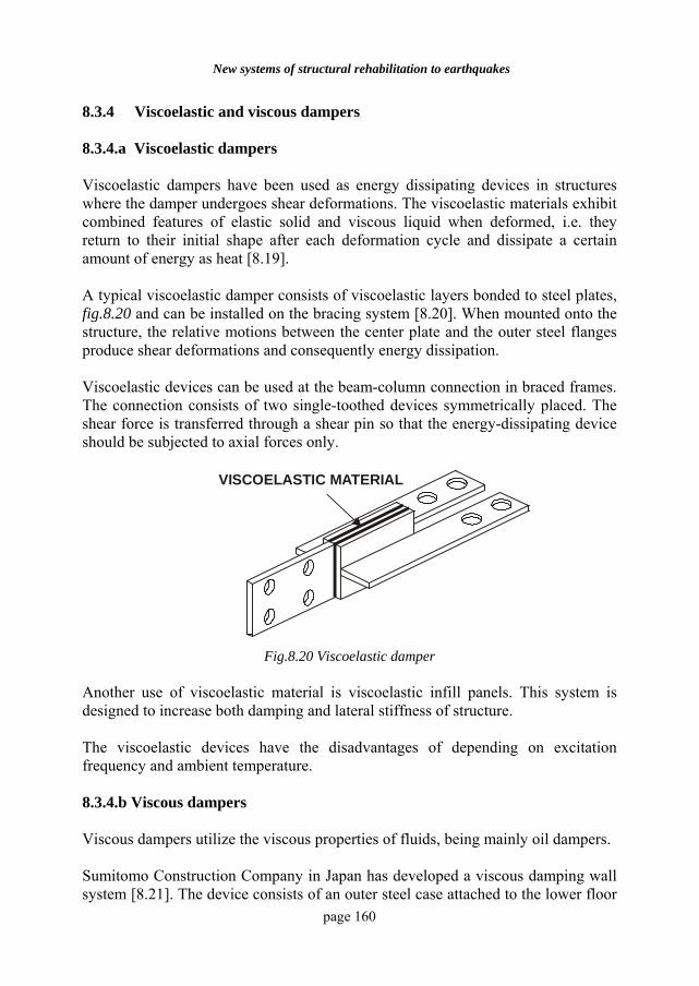
New systems of structural rehabilitation to earthquakes
page 160
8.3.4 Viscoelastic and viscous dampers 8.3.4.a Viscoelastic dampers Viscoelastic dampers have been used as energy dissipating devices in structures where the damper undergoes shear deformations. The viscoelastic materials exhibit combined features of elastic solid and viscous liquid when deformed, i.e. they return to their initial shape after each deformation cycle and dissipate a certain amount of energy as heat [8.19]. A typical viscoelastic damper consists of viscoelastic layers bonded to steel plates, fig.8.20 and can be installed on the bracing system [8.20]. When mounted onto the structure, the relative motions between the center plate and the outer steel flanges produce shear deformations and consequently energy dissipation. Viscoelastic devices can be used at the beam-column connection in braced frames. The connection consists of two single-toothed devices symmetrically placed. The shear force is transferred through a shear pin so that the energy-dissipating device should be subjected to axial forces only.
MATERIAL VASCOELASTIC
VISCOELASTIC MATERIAL
Fig.8.20 Viscoelastic damper
Another use of viscoelastic material is viscoelastic infill panels. This system is designed to increase both damping and lateral stiffness of structure. The viscoelastic devices have the disadvantages of depending on excitation frequency and ambient temperature. 8.3.4.b Viscous dampers Viscous dampers utilize the viscous properties of fluids, being mainly oil dampers. Sumitomo Construction Company in Japan has developed a viscous damping wall system [8.21]. The device consists of an outer steel case attached to the lower floor
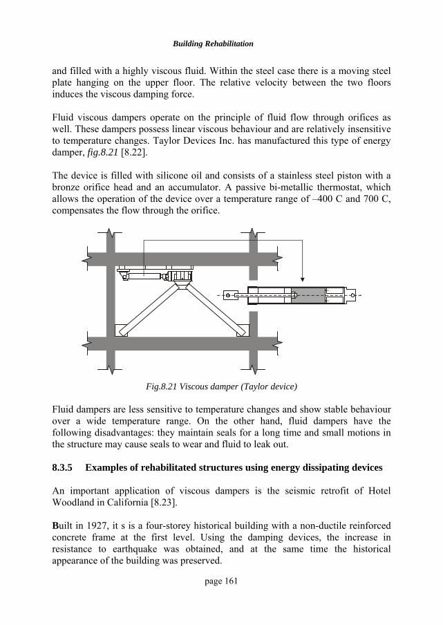
Building Rehabilitation
page 161
and filled with a highly viscous fluid. Within the steel case there is a moving steel plate hanging on the upper floor. The relative velocity between the two floors induces the viscous damping force. Fluid viscous dampers operate on the principle of fluid flow through orifices as well. These dampers possess linear viscous behaviour and are relatively insensitive to temperature changes. Taylor Devices Inc. has manufactured this type of energy damper, fig.8.21 [8.22]. The device is filled with silicone oil and consists of a stainless steel piston with a bronze orifice head and an accumulator. A passive bi-metallic thermostat, which allows the operation of the device over a temperature range of –400 C and 700 C, compensates the flow through the orifice.
Fig.8.21 Viscous damper (Taylor device)
Fluid dampers are less sensitive to temperature changes and show stable behaviour over a wide temperature range. On the other hand, fluid dampers have the following disadvantages: they maintain seals for a long time and small motions in the structure may cause seals to wear and fluid to leak out. 8.3.5 Examples of rehabilitated structures using energy dissipating devices An important application of viscous dampers is the seismic retrofit of Hotel Woodland in California [8.23]. Built in 1927, it s is a four-storey historical building with a non-ductile reinforced concrete frame at the first level. Using the damping devices, the increase in resistance to earthquake was obtained, and at the same time the historical appearance of the building was preserved.
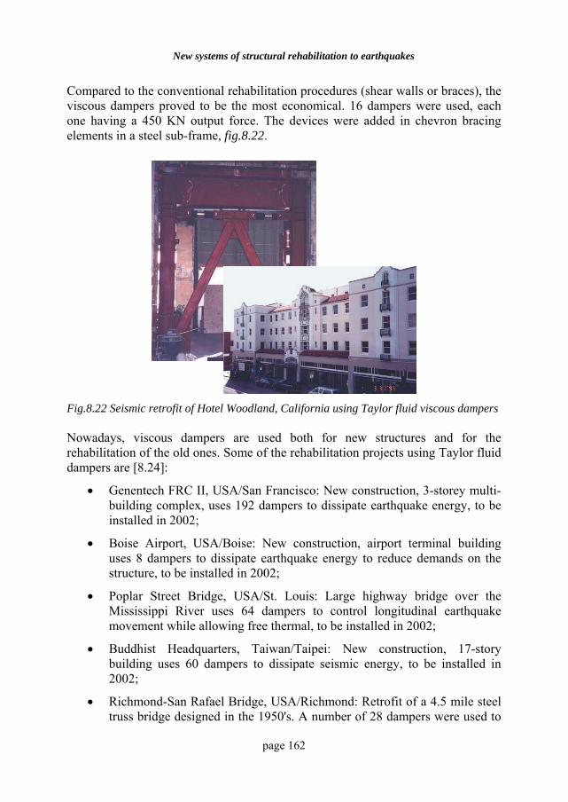
New systems of structural rehabilitation to earthquakes
page 162
Compared to the conventional rehabilitation procedures (shear walls or braces), the viscous dampers proved to be the most economical. 16 dampers were used, each one having a 450 KN output force. The devices were added in chevron bracing elements in a steel sub-frame, fig.8.22.
Fig.8.22 Seismic retrofit of Hotel Woodland, California using Taylor fluid viscous dampers Nowadays, viscous dampers are used both for new structures and for the rehabilitation of the old ones. Some of the rehabilitation projects using Taylor fluid dampers are [8.24]:
• Genentech FRC II, USA/San Francisco: New construction, 3-storey multi-building complex, uses 192 dampers to dissipate earthquake energy, to be installed in 2002;
• Boise Airport, USA/Boise: New construction, airport terminal building uses 8 dampers to dissipate earthquake energy to reduce demands on the structure, to be installed in 2002;
• Poplar Street Bridge, USA/St. Louis: Large highway bridge over the Mississippi River uses 64 dampers to control longitudinal earthquake movement while allowing free thermal, to be installed in 2002;
• Buddhist Headquarters, Taiwan/Taipei: New construction, 17-story building uses 60 dampers to dissipate seismic energy, to be installed in 2002;
• Richmond-San Rafael Bridge, USA/Richmond: Retrofit of a 4.5 mile steel truss bridge designed in the 1950's. A number of 28 dampers were used to
Building Rehabilitation
page 163
dissipate seismic energy and allow the bridge to withstand a maximum credible earthquake, to be installed in 2002;
• INTERCENTRO, Dominican Republic/Santo Domingo: New construction, 44-story steel frame building uses 48 dampers to dissipate earthquake energy to reduce demands on the structure, to be installed 2002;
• San Francisco-Oakland Bay Bridge, West Span-Suspension Bridge, USA/San Francisco: Retrofit of suspension span between San Francisco and Yerba Buena Island. 100 dampers were used to dissipate seismic energy, to be installed 2001/2002.
BIBLIOGRAPHY
8.1 *** Comment réparer les bâtiments endommagés par un seisme, Nations Unies, New York, 1977.
8.2 Budescu, M., Contribuţii privind izolarea seismică a structurilor, Teză de doctorat, Institutul Politehnic “Gh. Asachi” Iaşi, 1983.
8.3 Mayes, R.L., Seismic isolation: When content protection is as important as the structure, Proceedings Third National Concrete and Masonry Engineering Conference, vol. 2, San Francisco, California, 1995.
8.4 Nazin, V.V., Experimentalnîiezdania v Sevastopole na gravitaţionnîh sistemah seismoizolaţii s vkliuciaişcimsia suhîmtreniem, Seismostoikoe stroitelstvov Uzbekskoi SSR, Taşkent, 1974.
8.5 Robinson, W.H., Tucker, A.G., A Lead – Rubber Shear Damper, Bulletin of the New Zealand National Society for Earthquake Engineering, vol.10, nr.3, 1977.
8.6 Plichon, C., Hooped Rubber Bearing and Frictional Plates: A modern Antiseismic Engineering Technique, Proceedings, Specialists Meeting on the Anti-Seismic Design of Nuclear Installations, Paris, France, 1975.
8.7 Oakland City Hall (www.dis-inc.com/oakbrief.htm) 8.8 San Francisco City Hall (www.dis-inc.com/sfhallbr.htm 8.9 New Zealand Parliament House (www.dis-inc.com/nzparlbr.htm)
8.10 Protecting Rodin's Sculpture the "Gates of Hell" at the National Museum of Western Art Withstanding Earthquakes with Base Isolation Retrofit. (www.takenaka.co.jp/takenaka_e/news_e/pr9903/m9903_04.htm)
8.11 Kelly, J.M., Skinner, M.S., Beucke, K.E., Experimental Testing of an Energy-Absorbing Base Isolation System, UCB/EERC – 80/35.
8.12 Aristizabal-Ochoa, D., Disposable knee bracing: improvement in seismic design of steel frames, ASCE Journal of Structural Engineering, vol. 112, no. 7
8.13 Jurukovski, D., Petkovski, M., Rakicevic, Z., Energy absorbing elements in regular and composite steel frame structures, Eng. Structures, 1995
New systems of structural rehabilitation to earthquakes
page 164
8.14 Tyler, R.G., Damping in building structures by means of PTTF sliding joints, Bulletin of New Zealand Society of Earthquake Engineering, vol. 10, 1977
8.15 Tsai, K.C., Hong, C.P., Steel triangular plate energy absorber for earthquake-resistant buildings, Proceedings, 1st World Congress on Constructional Steel Design, Mexico, 1992
8.16 Robinson, W.H., Cousins, W.J., Recent developments in lead dampers for base isolation, Pacific Conference on Earthquake Engineering, vol. 2, New Zealand, 1987
8.17 Grigorian, C.E., Popov, E.P., Slotted bolted connections for energy dissipation, Proceeding ATC-17-1 Seminar on Seismic Isolation, Passive Energy Dissipation and Active Control, Applied Technology Council, Redwood City, CA, vol. 2, 1993
8.18 Nims, D.K., Inaudi, J.A., Richter, P.J., Kelly, J.M., Application of the energy dissipating restraint to buildings, Proceeding ATC-17-1 Seminar on Seismic Isolation, Passive Energy Dissipation and Active Control, Applied Technology Council, Redwood City, CA, vol. 2, 1993
8.19 Mahmoodi, P., Structural dampers, Journal of Structural Division, ASCE, vol. 95, 1969
8.20 Mahmoodi, P., Keel, C.J., Performance of viscoelastic structural dampers for the Columbia Center Building, Building Motion in Wind, ASCE publication, 1986
8.21 Miyazaki, M., Mitsusaka, Y., Design of a building with 20% or greater damping, Proceedings of the 10th World Conference on Earthquake Engineering, Madrid, 1992
8.22 Symans, M.D., Constantinou, M.C., Seismic response of structures with supplemental fluid viscous dampers, NCEER Bulletin, vol. 7, no. 4, 1993
8.23 Miyamoto, H.K., Seismic Rehabilitation of a Historic Concrete Structure Using Fluid Viscous Dampers, (www.msm1.com/pdf_files/HotelStockton.pdf)
8.24 Taylor, D., Constantinou, M.C., Fluid Dampers for Applications of Seismic Energy Dissipation and Seismic Isolation, (www.taylordevices.com/dampers.htm)
page 165
9 RC STRUCTURE REHABILITATION WITH
ADVANCED POLYMERIC COMPOSITES 9.1 INTRODUCTION Fibre reinforced polymer (FRP) composites are increasingly being utilised as alternatives to traditional construction materials for rehabilitation of infrastructure applications. The existing infrastructure is in real need of renewal due to deficiencies existing in construction works such as: wear, ageing of structural components, environmental deterioration, insufficient detailing at the time of original design, the use of substandard materials in initial construction, change in loading patterns and inadequate maintenance through the life of the structure [9.12], [9.13]. When rehabilitation of civil infrastructure is discussed, it is important to differentiate among repair, strengthening and retrofit. These three terms refer to different structural conditions: A composite is used in “repairing” when the FRP composite material is utilized to fix a structural or functional deficiency, such as a crack or a severely degraded element. The “strengthening” (nonseismic) of a structural member is specific to those situations where the application of the FRP composite enhances the existing design performance level. The term “retrofit” (seismic) is mostly used as a generic term for rehabilitation especially in relation to the seismic upgrade of load-carrying members. It is important to use these terms correctly on the basis of structural functionality and also because the specifics related to the use of FRPs in conjunction with existing traditional materials have a significant effect on the selection of fibre-matrix combinations [9.12].
RC structure rehabilitation with advanced polymeric composites
page 166
Traditional building materials and technologies are suitable in many situations and have a number of advantages, including the low cost of materials and construction. However they lack in longevity in some cases, and, in others are susceptible to rapid deterioration, emphasizing the need for better grades of these materials or newer technologies. In some cases design alternatives may be constrained by the current limitations of materials used, for example the size of a column due to restrictions on design and minimum dimension needed. In a similar manner, the use of conventional materials is often not possible in cases of retrofit or may be deemed as ineffective in terms of functionality. In other situations restraints such as dead load restrict the widening of current structures. In all such (and other) cases there is a critical need for the use of new materials and technologies, with the end of aim of facilitating functionality and greater structural and life-cycle efficiency. FRP composites give the designer a wide range of material choices to meet some specific structural requirements. They may have “tailored” properties derived from their anisotropy given by the arrangement of the fibre reinforcement in the polymeric resin. FRPs also have good corrosion resistance, high strength-to-weight ratio allowing their use in places and ways that are not available to traditional materials. These unique properties provide significant impetus for their use in rehabilitation and restoration of historic construction without causing significant changes to the features of the original structures. Also their performance combined with their light weight enable their use in strengthening severely degraded structural members, as well as in the modification of existing structures without egress on available headroom or open space [9.13]. 9.2 GENERAL CONSIDERATIONS FOR STRENGTHENING OF
CONCRETE STRUCTURES Strengthening of old and/or deteriorated reinforced concrete (RC) members is often required due to the following causes [9.27], [9.29]:
• The inadequacy of longitudinal reinforcement in beams and columns, leading to flexural failure. In such cases the bending capacity of concrete elements can be increased through the use of externally bonded FRP plates, strips or fabrics. Alternatively near-surface mounted strips or rods with the fibre direction parallel to the member axis can be utilised.
Building Rehabilitation
page 167
• The inadequacy of transverse reinforcement, which may have as effect brittle shear failure in structural members like columns, beams, shear walls and beam-column joints. The shear capacity of concrete members can be enhanced by providing externally bonded FRP with the fibres oriented in the transverse direction to the member axis direction, in the case of columns and beams, or in the direction of both the column and the beam direction in the case of beam-column joints.
• Poor detailing in the regions of flexural plastic hinges where the flexural cracking may be followed by cover concrete spalling, failure of transverse steel reinforcement, and buckling of longitudinal steel reinforcement or compressive crushing of concrete. This mode of failure is usually accompanied by large inelastic flexural deformation. By adding confinement in the form of FRP jackets with fibres placed along the column perimeter, the spalling of cover concrete is prevented and the buckling of the longitudinal steel bars is restrained. In this way more ductile responses can be developed and larger inelastic deformations can be sustained.
• Poor detailing in lap splices. This mode occurs in columns in which the longitudinal steel reinforcement is lap spliced in the maximum bending moment regions near the column ends. Debonding may occur once vertical cracks develop in the cover concrete and progresses with cover spalling. By increasing the lap confinement with fibres along the column perimeter the flexural strength degradation can be prevented or limited.
The use of FRP reinforcement cannot modify the stiffness characteristics of existing RC elements; hence the FRP strengthening technique is not applicable if the structural intervention is aiming at increasing stiffness rather than strength or ductility [9.29]. 9.3 ADHESIVE MATERIALS FOR STRUCTURAL STRENGTHENING
OF RC ELEMENTS Adhesives are substances capable of holding two materials together by surface attachment. The purpose of an adhesive is to produce a strong continuous bond between the surfaces of the adherends and to ensure that full composite action is developed by the transfer of shear stress across the thickness of the adhesive layer. To achieve such a purpose a good adhesion to the surfaces involved must be achieved and sustained [9.9]. The science of adhesion demands a consideration of concepts regarding surface chemistry, polymer chemistry, rheology, stress analysis and fracture mechanics. Most key information about adhesives relevant to their use must be provided by the manufacturer. The best results in structural strengthening
RC structure rehabilitation with advanced polymeric composites
page 168
have so far been achieved by using two-parts epoxy adhesives specially developed for use in the construction industry. Depending on the specific application the adhesive may contain fillers, softening inclusions, toughening additives and others. Application of an epoxy adhesive system requires the preparation of an adequate specification, which must include such provisions as mixing/application parameters and techniques, curing temperatures, surface preparation procedures, thermal expansion, creep properties, abrasion and chemical resistance. Three different time concepts must be considered when using epoxy adhesives, shelf life, pot life and open time. The unmixed shelf life is the period for which the individual (unmixed) components may be stored without undergoing significant deterioration. Pot life is time interval in which one can work with the adhesive after mixing the components before it starts to harden in the mixture vessel. Open time, when the adhesive has been applied to the adherends is the time that one can have after the adhesive has been applied to the adherends and before they are joined together. A typical open time may be of the order of 30 minutes. The principal requirements for bonding FRP composites to concrete and other structural materials are summarized in the following [9.11], [9.17]:
• It should have good adhesion to the materials involved.
• Two components of dissimilar colour to facilitate complete mixing.
• Tolerance to slight variations in the resin and hardener mix proportions.
• An ability to be applied in thicknesses of between 1 and 10 mm to accommodate irregularities of the adherends surface.
• A pot life of at least 40 minutes at normal temperature and relatively high humidity.
• Low shrinkage on curing.
• Strong bond between the adherends.
• Shear and tensile strength compatible to those of the adherends materials.
• The adhesive modulus should be high enough to avoid large creep but not excessively high to cause large stress concentrations.
• Acceptable fatigue performance over the use temperature range (-20 to +40oC).
• Long-term durability to maintain the integrity of the system over the planned life span.
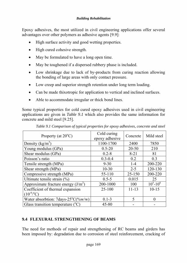
Building Rehabilitation
page 169
Epoxy adhesives, the most utilized in civil engineering applications offer several advantages over other polymers as adhesive agents [9.9]:
• High surface activity and good wetting properties.
• High cured cohesive strength.
• May be formulated to have a long open time.
• May be toughened if a dispersed rubbery phase is included.
• Low shrinkage due to lack of by-products from curing reaction allowing the bonding of large areas with only contact pressure.
• Low creep and superior strength retention under long term loading.
• Can be made thixotropic for application to vertical and inclined surfaces.
• Able to accommodate irregular or thick bond lines. Some typical properties for cold cured epoxy adhesives used in civil engineering applications are given in Table 9.1 which also provides the same information for concrete and mild steel [9.25].
Table 9.1 Comparison of typical properties for epoxy adhesives, concrete and steel
Property (at 20oC) Cold curing epoxy adhesive Concrete Mild steel
Density (kg/m3) 1100-1700 2400 7850 Young modulus (GPa) 0.5-20 20-50 210 Shear modulus (GPa) 0.2-8 8-21 81 Poisson’s ratio 0.3-0.4 0.2 0.3 Tensile strength (MPa) 9-30 1-4 200-220 Shear strength (MPa) 10-30 2-5 120-130 Compressive strength (MPa) 55-110 25-150 200-220 Ultimate tensile strain (%) 0.5-5 0.015 25 Approximate fracture energy (J/m2) 200-1000 100 105-106
Coefficient of thermal expansion (10-6/oC)
25-100 11-13 10-15
Water absorbtion: 7days-25oC(%w/w) 0.1-3 5 0 Glass transition temperature (oC) 45-80 - -
9.4 FLEXURAL STRENGTHENING OF BEAMS The need for methods of repair and strengthening of RC beams and girders has been imposed by: degradation due to corrosion of steel reinforcement, cracking of
RC structure rehabilitation with advanced polymeric composites
page 170
concrete due to excessive carbonation, freeze-thaw action, spalling of concrete cover, effects of alkali-silica reactions and changing in loading patterns [9.13]. In case of bridges the need for increasing their load carrying capacities requires the adoption of a cost-effective technology that will not distress the traffic significantly. In buildings the materials deterioration and changing needs for building occupancy imposes, in many cases, the strengthening of existing beams. One of the conventional methods for external strengthening implies the addition of adhesive-bonded steel plates on the tension side of the RC beams. The use of epoxy-bonded steel plates is very frequent in Europe and the United States but it suffers from a number of disadvantages:
• Steel plates are heavy and difficult to transport, handle and install.
• The length of individual steel plates is restricted to 8-10m to enable handling and even at these lengths it may be difficult to erect them due to pre-existing service facilities.
• Durability and corrosion effects remain uncertain.
• Contaminants on structural members prior to bonding.
• Surface preparation including the priming systems.
• Steel plate thickness at least 5 mm to prevent distortion during blasting operation.
• Complex profiles are difficult to be shaped with steel plates.
• Expensive falsework is required to maintain steel plates in position during bonding.
Composites fabricated either through wet processes on-site or prefabricated in strips and then adhesively bonded to the concrete surface provide an efficient means of strengthening, that can be carried out with no or little disruption in use. In general, polymeric composites can be applied in three ways as described in the following section. The efficacy of the method depends mainly on the appropriate selection of the composite material and on the efficiency and integrity of the bond between the composite and the concrete surface. Wet lay-up. In this procedure the polymeric resin is applied to the concrete substrate and layers of fabric made of carbon, glass or aramid fibres, and then impregnated in place using rollers (see fig.4.22). The composite and bond are formed at the same time. The procedure is quite slow and needs more setup.
Adhesive-bonding. The composite plate is prefabricated and cured (using pultrusion or another manufacturing procedure) and then bonded onto the concrete substrate
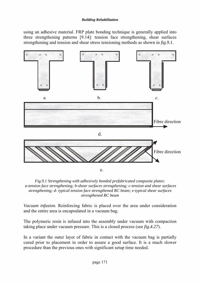
Building Rehabilitation
page 171
using an adhesive material. FRP plate bonding technique is generally applied into three strengthening patterns [9.14]: tension face strengthening, shear surfaces strengthening and tension and shear stress tensioning methods as shown in fig.9.1.
Fig.9.1 Strengthening with adhesively bonded prefabricated composite plates:
a-tension face strengthening; b-shear surfaces strengthening; c-tension and shear surfaces strengthening; d- typical tension face strengthened RC beam; e-typical shear surfaces
strengthened RC beam Vacuum infusion. Reinforcing fabric is placed over the area under consideration and the entire area is encapsulated in a vacuum bag. The polymeric resin is infused into the assembly under vacuum with compaction taking place under vacuum pressure. This is a closed process (see fig.4.27). In a variant the outer layer of fabric in contact with the vacuum bag is partially cured prior to placement in order to assure a good surface. It is a much slower procedure than the previous ones with significant setup time needed.
a. b. c.
d.
e.
Fibre direction
Fibre direction
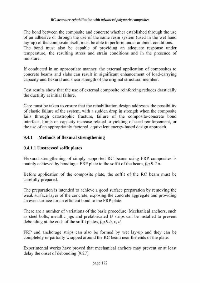
RC structure rehabilitation with advanced polymeric composites
page 172
The bond between the composite and concrete whether established through the use of an adhesive or through the use of the same resin system (used in the wet hand lay-up) of the composite itself, must be able to perform under ambient conditions. The bond must also be capable of providing an adequate response under temperature, the resulting stress and strain conditions and in the presence of moisture. If conducted in an appropriate manner, the external application of composites to concrete beams and slabs can result in significant enhancement of load-carrying capacity and flexural and shear strength of the original structural member. Test results show that the use of external composite reinforcing reduces drastically the ductility at initial failure. Care must be taken to ensure that the rehabilitation design addresses the possibility of elastic failure of the system, with a sudden drop in strength when the composite fails through catastrophic fracture, failure of the composite-concrete bond interface, limits on capacity increase related to yielding of steel reinforcement, or the use of an appropriately factored, equivalent energy-based design approach. 9.4.1 Methods of flexural strengthening 9.4.1.1 Unstressed soffit plates Flexural strengthening of simply supported RC beams using FRP composites is mainly achieved by bonding a FRP plate to the soffit of the beam, fig.9.2.a. Before application of the composite plate, the soffit of the RC beam must be carefully prepared. The preparation is intended to achieve a good surface preparation by removing the weak surface layer of the concrete, exposing the concrete aggregate and providing an even surface for an efficient bond to the FRP plate. There are a number of variations of the basic procedure. Mechanical anchors, such as steel bolts, metallic jigs and prefabricated U strips can be installed to prevent debonding at the ends of the soffit plates, fig.9.b, c, d. FRP end anchorage strips can also be formed by wet lay-up and they can be completely or partially wrapped around the RC beam near the ends of the plate. Experimental works have proved that mechanical anchors may prevent or at least delay the onset of debonding [9.27].
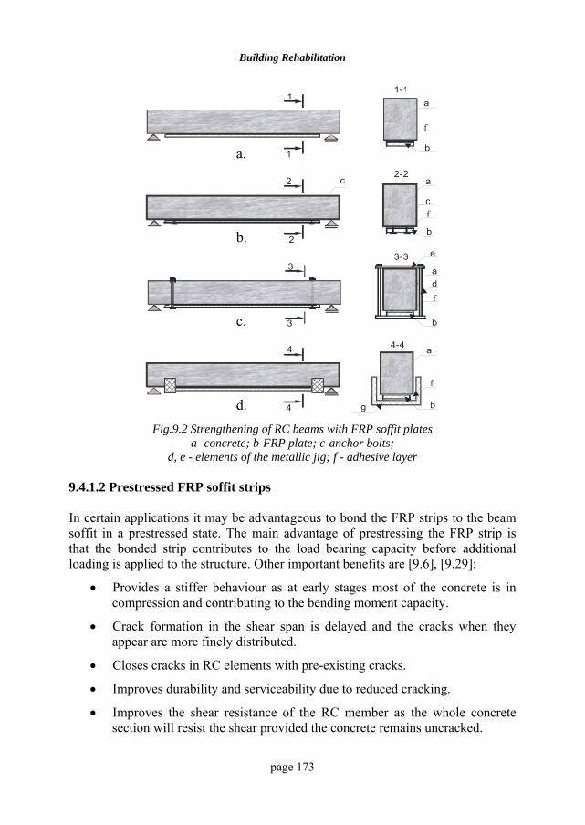
Building Rehabilitation
page 173
a1-1
b1
3
3
3-3
b
ad
e
4
4
4-4 a
f
b g
2
2
2-2a
c
b
c
1
f
f
f
Fig.9.2 Strengthening of RC beams with FRP soffit plates
a- concrete; b-FRP plate; c-anchor bolts; d, e - elements of the metallic jig; f - adhesive layer
9.4.1.2 Prestressed FRP soffit strips In certain applications it may be advantageous to bond the FRP strips to the beam soffit in a prestressed state. The main advantage of prestressing the FRP strip is that the bonded strip contributes to the load bearing capacity before additional loading is applied to the structure. Other important benefits are [9.6], [9.29]:
• Provides a stiffer behaviour as at early stages most of the concrete is in compression and contributing to the bending moment capacity.
• Crack formation in the shear span is delayed and the cracks when they appear are more finely distributed.
• Closes cracks in RC elements with pre-existing cracks.
• Improves durability and serviceability due to reduced cracking.
• Improves the shear resistance of the RC member as the whole concrete section will resist the shear provided the concrete remains uncracked.
a. b. c. d.
RC structure rehabilitation with advanced polymeric composites
page 174
• Smaller areas of FRP strips are required to achieve the same strengthening effect.
• Some failure modes associated with peeling-off at cracks at the ends of FRP plates can be avoided.
• A greater structural efficiency can be obtained since the neutral axis remains at a lower level in the prestressed case than in the unstressed one.
• The yielding of the steel reinforcement commences at an increased load compared to that of a non-stressed RC member.
This technique has, however, some disadvantages:
• It is more expensive due to the lager number of operations and equipment that is required by the process of prestressing.
• The duration of the process is longer.
• The equipment needed to push the FRP strip to the soffit must be kept in place until the adhesive layer has become hard enough.
The concept of applying a prestressed FRP plate is illustrated in fig.9.3.
a.
b.
c.
d. Fig.9.3 Strengthening of RC beams with prestressed FRP plates:
a-prestressing; b-bonding; c-end anchorage and FRP plate release upon hardening of the adhesive; d-active anchorage [9.6]
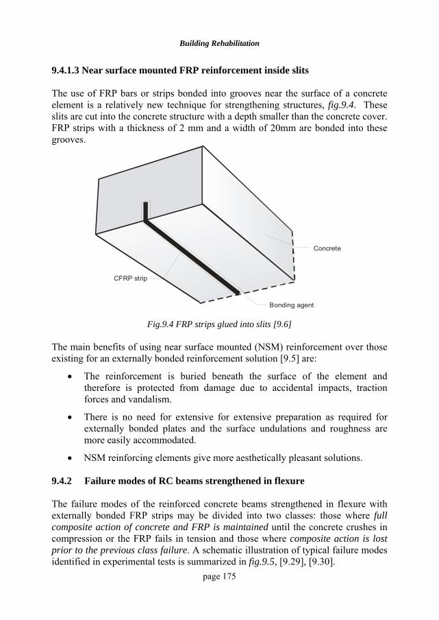
Building Rehabilitation
page 175
9.4.1.3 Near surface mounted FRP reinforcement inside slits The use of FRP bars or strips bonded into grooves near the surface of a concrete element is a relatively new technique for strengthening structures, fig.9.4. These slits are cut into the concrete structure with a depth smaller than the concrete cover. FRP strips with a thickness of 2 mm and a width of 20mm are bonded into these grooves.
Concrete
Bonding agent
CFRP strip
Fig.9.4 FRP strips glued into slits [9.6]
The main benefits of using near surface mounted (NSM) reinforcement over those existing for an externally bonded reinforcement solution [9.5] are:
• The reinforcement is buried beneath the surface of the element and therefore is protected from damage due to accidental impacts, traction forces and vandalism.
• There is no need for extensive for extensive preparation as required for externally bonded plates and the surface undulations and roughness are more easily accommodated.
• NSM reinforcing elements give more aesthetically pleasant solutions. 9.4.2 Failure modes of RC beams strengthened in flexure The failure modes of the reinforced concrete beams strengthened in flexure with externally bonded FRP strips may be divided into two classes: those where full composite action of concrete and FRP is maintained until the concrete crushes in compression or the FRP fails in tension and those where composite action is lost prior to the previous class failure. A schematic illustration of typical failure modes identified in experimental tests is summarized in fig.9.5, [9.29], [9.30].
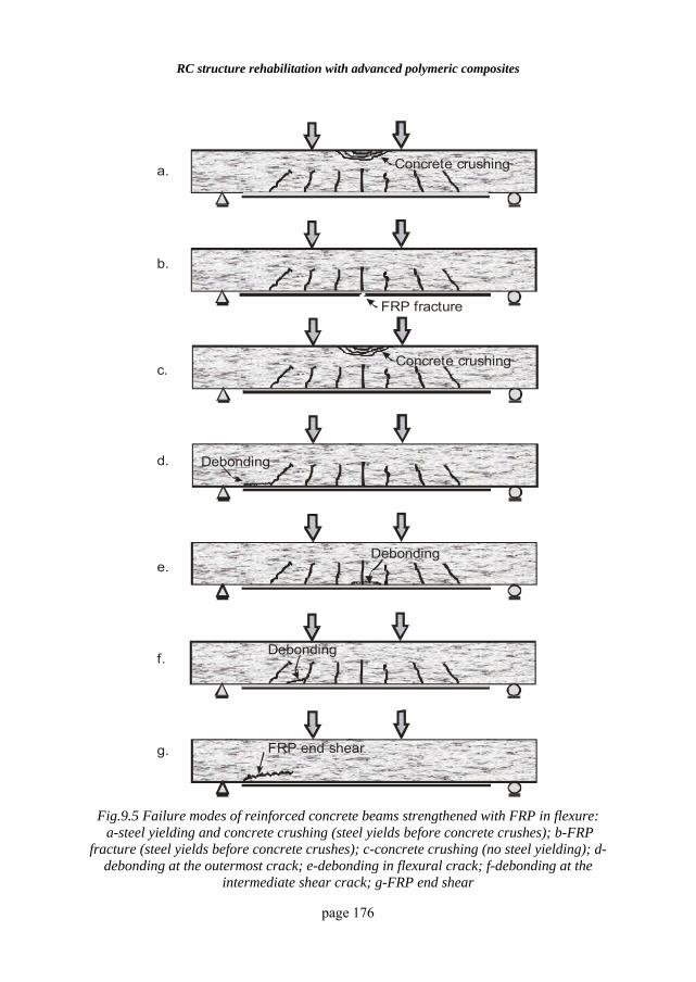
RC structure rehabilitation with advanced polymeric composites
page 176
Concrete crushing
FRP fracture
Concrete crushing
Debonding
a.
b.
c.
d.
e.
f.
g.
Debonding
Debonding
FRP end shear
Fig.9.5 Failure modes of reinforced concrete beams strengthened with FRP in flexure: a-steel yielding and concrete crushing (steel yields before concrete crushes); b-FRP
fracture (steel yields before concrete crushes); c-concrete crushing (no steel yielding); d-debonding at the outermost crack; e-debonding in flexural crack; f-debonding at the
intermediate shear crack; g-FRP end shear
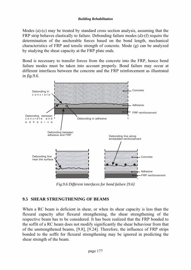
Building Rehabilitation
page 177
Modes (a)-(c) may be treated by standard cross section analysis, assuming that the FRP strip behaves elastically to failure. Debonding failure modes (d)-(f) require the determination of the anchorable forces based on the bond length, mechanical characteristics of FRP and tensile strength of concrete. Mode (g) can be analyzed by studying the shear capacity at the FRP plate ends. Bond is necessary to transfer forces from the concrete into the FRP, hence bond failure modes must be taken into account properly. Bond failure may occur at different interfaces between the concrete and the FRP reinforcement as illustrated in fig.9.6.
Concrete
Adhesive
FRP reinforcement
Debonding in c o n c r e t e
Debonding between c o n c r e t e a n d a d h e s i v e
Debonding in adhesive
Debonding between adhesive and FRP
Debonding line near the surface
Debonding line along embedded reinforcement
Concrete
AdhesiveFRP reinforcement
Fig.9.6 Different interfaces for bond failure [9.6]
9.5 SHEAR STRENGTHENING OF BEAMS When a RC beam is deficient in shear, or when its shear capacity is less than the flexural capacity after flexural strengthening, the shear strengthening of the respective beam has to be considered. It has been realized that the FRP bonded to the soffit of a RC beam does not modify significantly the shear behaviour from that of the unstrengthened beams, [9.8], [9.24]. Therefore, the influence of FRP strips bonded to the soffit for flexural strengthening may be ignored in predicting the shear strength of the beam.
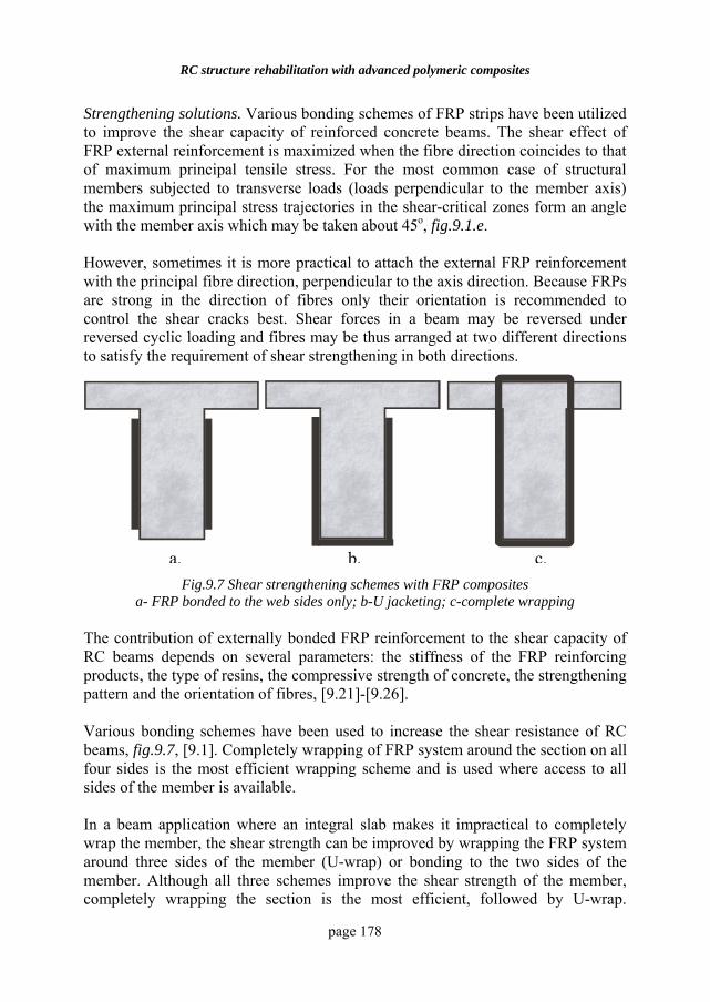
RC structure rehabilitation with advanced polymeric composites
page 178
Strengthening solutions. Various bonding schemes of FRP strips have been utilized to improve the shear capacity of reinforced concrete beams. The shear effect of FRP external reinforcement is maximized when the fibre direction coincides to that of maximum principal tensile stress. For the most common case of structural members subjected to transverse loads (loads perpendicular to the member axis) the maximum principal stress trajectories in the shear-critical zones form an angle with the member axis which may be taken about 45o, fig.9.1.e. However, sometimes it is more practical to attach the external FRP reinforcement with the principal fibre direction, perpendicular to the axis direction. Because FRPs are strong in the direction of fibres only their orientation is recommended to control the shear cracks best. Shear forces in a beam may be reversed under reversed cyclic loading and fibres may be thus arranged at two different directions to satisfy the requirement of shear strengthening in both directions.
Fig.9.7 Shear strengthening schemes with FRP composites a- FRP bonded to the web sides only; b-U jacketing; c-complete wrapping
The contribution of externally bonded FRP reinforcement to the shear capacity of RC beams depends on several parameters: the stiffness of the FRP reinforcing products, the type of resins, the compressive strength of concrete, the strengthening pattern and the orientation of fibres, [9.21]-[9.26]. Various bonding schemes have been used to increase the shear resistance of RC beams, fig.9.7, [9.1]. Completely wrapping of FRP system around the section on all four sides is the most efficient wrapping scheme and is used where access to all sides of the member is available. In a beam application where an integral slab makes it impractical to completely wrap the member, the shear strength can be improved by wrapping the FRP system around three sides of the member (U-wrap) or bonding to the two sides of the member. Although all three schemes improve the shear strength of the member, completely wrapping the section is the most efficient, followed by U-wrap.
a. b. c.
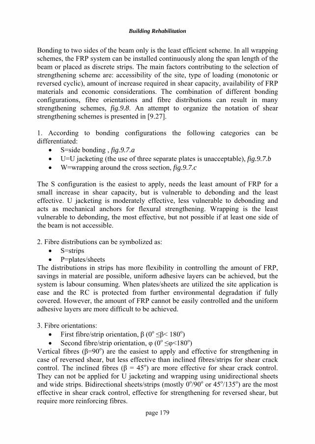
Building Rehabilitation
page 179
Bonding to two sides of the beam only is the least efficient scheme. In all wrapping schemes, the FRP system can be installed continuously along the span length of the beam or placed as discrete strips. The main factors contributing to the selection of strengthening scheme are: accessibility of the site, type of loading (monotonic or reversed cyclic), amount of increase required in shear capacity, availability of FRP materials and economic considerations. The combination of different bonding configurations, fibre orientations and fibre distributions can result in many strengthening schemes, fig.9.8. An attempt to organize the notation of shear strengthening schemes is presented in [9.27]. 1. According to bonding configurations the following categories can be differentiated:
• S=side bonding , fig.9.7.a • U=U jacketing (the use of three separate plates is unacceptable), fig.9.7.b • W=wrapping around the cross section, fig.9.7.c
The S configuration is the easiest to apply, needs the least amount of FRP for a small increase in shear capacity, but is vulnerable to debonding and the least effective. U jacketing is moderately effective, less vulnerable to debonding and acts as mechanical anchors for flexural strengthening. Wrapping is the least vulnerable to debonding, the most effective, but not possible if at least one side of the beam is not accessible. 2. Fibre distributions can be symbolized as:
• S=strips • P=plates/sheets
The distributions in strips has more flexibility in controlling the amount of FRP, savings in material are possible, uniform adhesive layers can be achieved, but the system is labour consuming. When plates/sheets are utilized the site application is ease and the RC is protected from further environmental degradation if fully covered. However, the amount of FRP cannot be easily controlled and the uniform adhesive layers are more difficult to be achieved. 3. Fibre orientations:
• First fibre/strip orientation, β (0o ≤β< 180o) • Second fibre/strip orientation, φ (0o ≤φ<180o)
Vertical fibres (β=90o) are the easiest to apply and effective for strengthening in case of reversed shear, but less effective than inclined fibres/strips for shear crack control. The inclined fibres (β = 45o) are more effective for shear crack control. They can not be applied for U jacketing and wrapping using unidirectional sheets and wide strips. Bidirectional sheets/strips (mostly 0o/90o or 45o/135o) are the most effective in shear crack control, effective for strengthening for reversed shear, but require more reinforcing fibres.
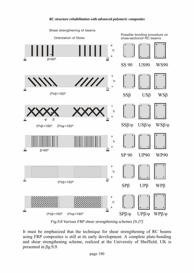
RC structure rehabilitation with advanced polymeric composites
page 180
Shear strengthening of beamsPossible bonding procedure on cross-sectionof RC beamsOrientation of fibres
h
β=90º
φ
h
0º <18≤ 0ºβ
β
0º <18≤ 0ºβ 0º <18φ≤ 0º
h
β=90º
0º <18≤ 0ºβ
0º <18≤ 0ºβ 0º <18φ≤ 0º
h
h
h
Fig.9.8 Various FRP shear strengthening schemes [9.27]
It must be emphasized that the technique for shear strengthening of RC beams using FRP composites is still at its early development. A complete plate-bonding and shear strengthening scheme, realized at the University of Sheffield, UK is presented in fig.9.9.
SS 90 US90 WS90
SSβ USβ WSβ
SSβ/φ USβ/φ WSβ/φ
SP 90 UP90 WP90
SPβ/φ UPβ/φ WPβ/φ
SPβ UPβ WPβ
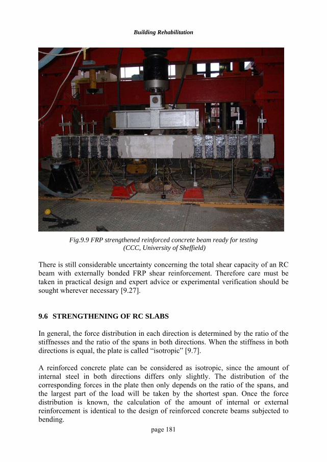
Building Rehabilitation
page 181
Fig.9.9 FRP strengthened reinforced concrete beam ready for testing
(CCC, University of Sheffield) There is still considerable uncertainty concerning the total shear capacity of an RC beam with externally bonded FRP shear reinforcement. Therefore care must be taken in practical design and expert advice or experimental verification should be sought wherever necessary [9.27]. 9.6 STRENGTHENING OF RC SLABS In general, the force distribution in each direction is determined by the ratio of the stiffnesses and the ratio of the spans in both directions. When the stiffness in both directions is equal, the plate is called “isotropic” [9.7]. A reinforced concrete plate can be considered as isotropic, since the amount of internal steel in both directions differs only slightly. The distribution of the corresponding forces in the plate then only depends on the ratio of the spans, and the largest part of the load will be taken by the shortest span. Once the force distribution is known, the calculation of the amount of internal or external reinforcement is identical to the design of reinforced concrete beams subjected to bending.
RC structure rehabilitation with advanced polymeric composites
page 182
The advantage of the thin FRP strips is the fact that they can be applied in both directions. In that way, the strengthened concrete plate remains isotropic, which means that the relative force distribution will not change. Since reinforced concrete plates are much thinner than concrete beams the lever arm from the resulting concrete compressive force to the external reinforcement is much larger than the lever arm to the internal steel reinforcement. This means that the active tensile stresses in the external FRP reinforcement can be much higher than in the internal steel reinforcement and the high resistance of the FRP reinforcement can be efficiently utilised. Therefore FRP laminates can often be used more effectively for strengthening concrete plates than for strengthening concrete beams. However when FRP strips are utilised, the deformations might be unacceptable, since the contribution of the externally bonded reinforcement to the plate stiffness is relatively small. The strengthening of RC slabs is expanding but the results obtained from the application of composites to beams cannot be directly extrapolated to application of slabs, especially as related to the selection of the form and positioning of the external reinforcement. This application is considered mainly for deficient structures where local punching shear failures are seen. A common conventional method is the complete reconstruction of the damaged area, very often at significant cost and with distress to traffic. FRP composites can easily be applied without any disruption of traffic. If the repair scheme is designed properly, the external FRP composite reinforcement will repair the area damaged by punching shear and will also prevent the opening of the existing cracks. The repair of this deficiency can be easily performed through the use of adhesively bonded pultruded composite strips and through wet lay-up of unidirectional fabrics. Similar schemes can be applied for the strengthening and repair of floor slabs of parking garages, which often suffer rapid deterioration due to salt-induced cracking, efflorescence of concrete and corrosion of steel reinforcement. The use of composite strips provides an efficient mechanism for repair where installation of liftwells in buildings results in cutting through existing steel reinforcement to form a cutout. Composite strips or bands can be easily applied externally to make up the lost reinforcing capacity, and to provide the means for redistribution of the loads and resulting stresses. Where preexisting slabs have to be cut for the installation of a liftwell during changes in building use, conventional methods would result in the construction of
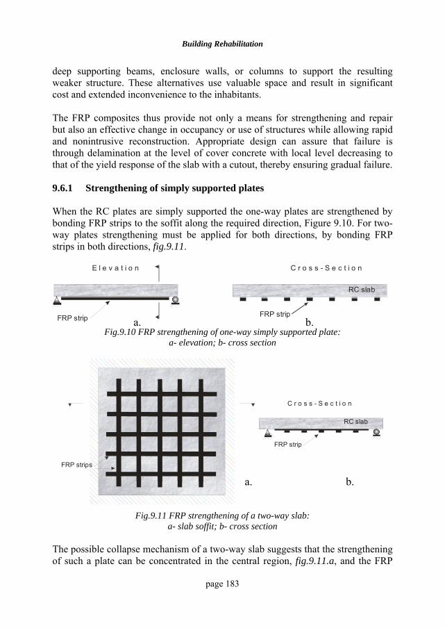
Building Rehabilitation
page 183
deep supporting beams, enclosure walls, or columns to support the resulting weaker structure. These alternatives use valuable space and result in significant cost and extended inconvenience to the inhabitants. The FRP composites thus provide not only a means for strengthening and repair but also an effective change in occupancy or use of structures while allowing rapid and nonintrusive reconstruction. Appropriate design can assure that failure is through delamination at the level of cover concrete with local level decreasing to that of the yield response of the slab with a cutout, thereby ensuring gradual failure. 9.6.1 Strengthening of simply supported plates When the RC plates are simply supported the one-way plates are strengthened by bonding FRP strips to the soffit along the required direction, Figure 9.10. For two-way plates strengthening must be applied for both directions, by bonding FRP strips in both directions, fig.9.11.
FRP strip
E l e v a t i o n C r o s s - S e c t i o n
FRP strip
RC slab
Fig.9.10 FRP strengthening of one-way simply supported plate:
a- elevation; b- cross section
C r o s s - S e c t i o n
RC slab
FRP strip
FRP strips
Fig.9.11 FRP strengthening of a two-way slab:
a- slab soffit; b- cross section The possible collapse mechanism of a two-way slab suggests that the strengthening of such a plate can be concentrated in the central region, fig.9.11.a, and the FRP
a. b.
a. b.
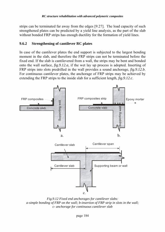
RC structure rehabilitation with advanced polymeric composites
page 184
strips can be terminated far away from the edges [9.27]. The load capacity of such strengthened plates can be predicted by a yield line analysis, as the part of the slab without bonded FRP strips has enough ductility for the formation of yield lines. 9.6.2 Strengthening of cantilever RC plates In case of the cantilever plates the end support is subjected to the largest bending moment in the slab, and therefore the FRP strips can not be terminated before the fixed end. If the slab is cantilevered from a wall, the strips may be bent and bonded onto the wall surface, fig.9.12.a, if the wet lay up process is adopted. Inserting of FRP strips into slots predrilled in the wall provides a sound anchorage, fig.9.12.b. For continuous cantilever plates, the anchorage of FRP strips may be achieved by extending the FRP strips to the inside slab for a sufficient length, fig.9.12.c.
Epoxy mortarFRP composites strip
Concrete slab
Sup
porti
ng w
all
FRP composites
Concrete slab
Supp
ortin
g w
a ll
Cantilever slab Cantilever span
Cantilever slab Supporting beam or wall
Fig.9.12 Fixed end anchorages for cantilever slabs:
a-simple bonding of FRP on the wall; b-insertion of FRP strip in slots in the wall; c- anchorage for continuous cantilever slab
a. b.
c.
Building Rehabilitation
page 185
9.7 STRENGTHENING OF RC COLUMNS 9.7.1 General Conventional strengthening measures for RC columns range from the external confinement of the core by heavily reinforced external concrete sections to the use of steel cables wound helically around the existing column at close spacing that are then covered by concrete and the use of steel jackets welded together in the field confining the existing columns, [9.2], [9.3]. Some of these methods are effective but they have some disadvantages [9.13]:
• They are time consuming and labour intensive;
• Can cause significant interruption of the structure functioning due to access and space requirements for heavy equipment;
• Rely on field welding, the quality of which is often questionable;
• Susceptible to degradation due to corrosion;
• Introduce changes in column stiffness, influencing the seismic force levels. The strengthening of existing RC columns using steel or FRP jacketing is based on a well established fact that lateral confinement of concrete can substantially enhance its axial compressive strength and ductility [9.15]. The most common form of FRP column strengthening involves the external wrapping of FRP straps. The use of FRP composites provides a means for confinement without the increase in stiffness (when only hoop reinforcing fibres are utilised), enables rapid fabrication of cost effective and durable jackets, with little or no traffic disruption in most cases. In FRP-confined concrete subjected to axial compression, the FRP jackets are loaded mainly in hoop tension while the concrete is subjected to tri-axial compression, so that both materials are used to their best advantages. As a result of the confinement, both the strength and the ultimate strain of concrete can be enhanced, while the tensile strength of FRP can be effectively utilized [9.3]. Instead of the brittle behaviour exhibited by both materials, FRP-confined concrete possesses an enhanced ductility [9.28]. For FRP wrapped, axially loaded columns the design philosophy relies on the wrap to carry tensile forces around the perimeter of the column as a result of lateral expansion of the underlying column when loaded axially in compression, [9.18], [9.19]. Constraining the lateral expansion of the column confines the concrete and, consequently increases its axial compressive capacity. It should be underlined that passive confinement of this type requires significant lateral expansion of the concrete before the FRP wrap is loaded
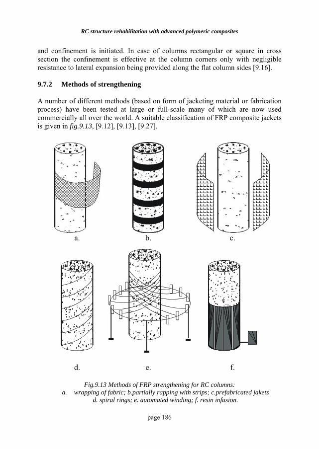
RC structure rehabilitation with advanced polymeric composites
page 186
and confinement is initiated. In case of columns rectangular or square in cross section the confinement is effective at the column corners only with negligible resistance to lateral expansion being provided along the flat column sides [9.16]. 9.7.2 Methods of strengthening A number of different methods (based on form of jacketing material or fabrication process) have been tested at large or full-scale many of which are now used commercially all over the world. A suitable classification of FRP composite jackets is given in fig.9.13, [9.12], [9.13], [9.27].
a. b. c.
d. e. f.
Fig.9.13 Methods of FRP strengthening for RC columns: a. wrapping of fabric; b.partially rapping with strips; c.prefabricated jakets
d. spiral rings; e. automated winding; f. resin infusion.
Building Rehabilitation
page 187
Wrapping. The most common technique for column strengthening using FRP composites has been in situ FRP wrapping. In this technique woven fabric sheets or unidirectional fibre sheets are impregnated with polymer resins and wrapped around the RC column. In the wet lay-up process the main fibres are orientated in the hoop direction, with cure taking place, generally, under ambient conditions. A column can be fully wrapped with FRP sheets in single or multiple layers, fig.9.13.a. It can also be partially wrapped using FRP straps in a continuous spiral, fig.9.13.b, or discrete rings. This method is very flexible in coping with different column shapes, ease in site handling and does not require special equipment. It is the most labour intensive and enables the least quality control. Filament winding. In filament winding, fig.9.13.e, the process is automated but essentially follows the same patterns with the difference being that the ensuing jacket has a nominal prestress due to the use of winding tension. The process can be automatically controlled using a computer controlled winding machine. A FRP membrane with imposed thickness, fibre orientation and fibre volume fraction can be achieved in this process. The use of prepreg tows has the advantage of using standardized and uniform materials that are easy for the structural designer to specify and it also presents the opportunity for elevated temperature cure. An improved quality control and reduced on-site labour are among the advantages of this technique. However this method has less flexibility in coping with different column shapes and requires special equipment. Prefabricated shell jacketing. In case of adhesively bonded shells, prefabricated single or dual-section jackets can be assembled in the field through bonding and layering. The shells are fabricated in half circles, fig.9.13.c, or half rectangles and circles with a slit or in continuous rolls prior to field installation, so that they can be opened and placed around the column. For effective FRP confinement to be achieved, a full contact between the column and the FRP jacket is needed. This can be achieved by bonding the shell to the column using adhesives or injecting shrinkage-compensated grout or mortar into the space between the shell and the column [9.4], [9.20]. The process affords a high level of materials quality control due to prefabrication of the elements under factory conditions, requires least on-site labour, enables column shape modification but as in the case of external strengthening relies on the integrity of the adhesive bond and has limited flexibility in coping with different column shapes. For rectangular columns to be strengthened by wrapping, their corners must be rounded. This rounding is needed to reduce the detrimental effect of the sharp corners on the tensile strength of FRP wraps and to enhance the effectiveness of confinement. If rectangular prefabricated shells are used, the shells are generally
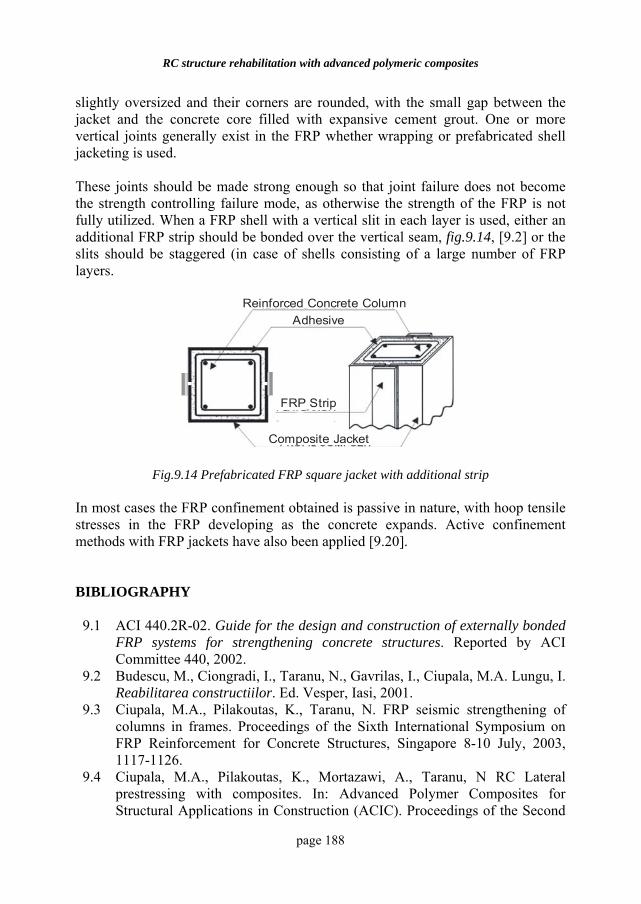
RC structure rehabilitation with advanced polymeric composites
page 188
slightly oversized and their corners are rounded, with the small gap between the jacket and the concrete core filled with expansive cement grout. One or more vertical joints generally exist in the FRP whether wrapping or prefabricated shell jacketing is used. These joints should be made strong enough so that joint failure does not become the strength controlling failure mode, as otherwise the strength of the FRP is not fully utilized. When a FRP shell with a vertical slit in each layer is used, either an additional FRP strip should be bonded over the vertical seam, fig.9.14, [9.2] or the slits should be staggered (in case of shells consisting of a large number of FRP layers.
FRP Strip
Composite Jacket
Reinforced Concrete Column Adhesive
Fig.9.14 Prefabricated FRP square jacket with additional strip
In most cases the FRP confinement obtained is passive in nature, with hoop tensile stresses in the FRP developing as the concrete expands. Active confinement methods with FRP jackets have also been applied [9.20]. BIBLIOGRAPHY 9.1 ACI 440.2R-02. Guide for the design and construction of externally bonded
FRP systems for strengthening concrete structures. Reported by ACI Committee 440, 2002.
9.2 Budescu, M., Ciongradi, I., Taranu, N., Gavrilas, I., Ciupala, M.A. Lungu, I. Reabilitarea constructiilor. Ed. Vesper, Iasi, 2001.
9.3 Ciupala, M.A., Pilakoutas, K., Taranu, N. FRP seismic strengthening of columns in frames. Proceedings of the Sixth International Symposium on FRP Reinforcement for Concrete Structures, Singapore 8-10 July, 2003, 1117-1126.
9.4 Ciupala, M.A., Pilakoutas, K., Mortazawi, A., Taranu, N RC Lateral prestressing with composites. In: Advanced Polymer Composites for Structural Applications in Construction (ACIC). Proceedings of the Second
Building Rehabilitation
page 189
International Conference, held at the University of Surrey, Guildford, UK on 20-22 April 2004, 195-202.
9.5 Farmer, N. Near surface mounted reinforcement for strengthening-UK experience and development of best practice. In: Advanced Polymer Composites for Structural Applications in Construction (ACIC). Proceedings of the Second International Conference, held at the University of Surrey, Guildford, UK on 20-22 April 2004 pp 659-666.
9.6 Federation International du Beton (FIB), “Externally bonded FRP reinforcement for RC structures”, Bulletin 14, Lausanne, 2001.
9.7 Gemert, V. D., Ignoul, S., Brosens, K. Strengthening of concrete constructions with externally bonded reinforcement. Design concepts and case studies. In Proceedings of the First International Conference on Innovative Materials and Technologies for Construction and Restoration. Lecce, June 6-9, 2004, 107-116.
9.8 Guadagnini, M., Shear behaviour and design of FRP RC beams. PhD Thesis, The University of Sheffield, UK, 2002.
9.9 Hollaway, L. C. and Leeming, M.B. “Strengthening of Reinforced Concrete Structures”. CRC Press, Woodhead Publishing Limited, Cambridge, 1999.
9.10 Hollaway, L. C., The evolution and the way forward for advanced polymer composites in the civil infrastructure. Constr. and Build. Mat. 17, 2003, 365-378.
9.11 Hutchinson, A. R. and Quinn, J. ”Materials”. In “Strengthening of Reinforced Concrete Structures”. Hollaway, L.C. and Leeming, M.B. eds., CRC Press, Woodhead Publishing Limited, Cambridge, 1999.
9.12 Karbhari, V. M., Civil Infrastructure Applications. In: Composites Vol. 21, ASM International, Ohio, 2001.
9.13 Karbhari, V.M., Seible, F. Fiber reinforced composites-advanced materials for renewal of civil infrastructure. Appl. Comp. Mater. 7, 95-124, 2000.
9.14 Lau, T.K., Zhou, L.M., Tse, P.C., Yuan, L.B. Applications of composites, optical fibre sensors and smart composites for concrete rehabilitation: an overview. Appl. Comp. Mater. 9: 221-247, 2002.
9.15 Mander, J.P., Priestley, M.J.N., Park, R. Theoretical stress-strain model for confined concrete. Journ. of Struct. Eng., ASCE, Vol. 114, No 8, 1804-1826, 1988.
9.16 Masia, M.J., Gale, T.N., Shrive N.G. Size effect in axially loaded square-section concrete prisms strengthened using carbon fibre reinforced polymer wrapping. Can. J. Civ. Eng. 31, 1-13, 2004.
9.17 Mays, G. C. and Hutchinson, A.R. “Adhesives in civil engineering”, Cambridge University Press, Cambridge, 1992.
9.18 Modarelli, R., Manni, O., Rametta, P. Confinement of RC columns with FRP materials: a critical comparison between ACI and CEB-FIP design guidelines. In Proceedings of the First International Conference on Innovative Materials and Technologies for Construction and Restoration.
RC structure rehabilitation with advanced polymeric composites
page 190
Lecce, June 6-9 2004, 285-297. 9.19 Monti, G. Confining reinforced concrete with FRP: behaviour and
modeling. In Composites in Construction a Reality. Proceedings of the International Workshop, Capri, July 20-21, 2001, 213-222.
9.20 Mortazavi,A., Behaviour of concrete confined with lateral pretensioned FRP, PhD Thesis, University of Sheffield, 2003.
9.21 Neale, K. Strengthening reinforced concrete structures with externally-bonded fibre reinforced polymers. ISIS Canada, Design Manual No 4, Winnipeg, 2001.
9.22 Oprisan,G., Taranu, N., Saftiuc, C., Entuc, I., Strengthening of reinforced concrete beams with carbon fibre reinforced polymer plates. In Bull. of the Polytechnic Inst of Iasi, Tom XLIX, Fasc. 3-4, 2003, 97-106.
9.23 Pellegrino, C., Modena, C. Fiber reinforced polymer shear strengthening of reinforced concrete beams with transverse steel reinforcement. Journ. of comp. for constr., Vol. 6, 2, 104-111, 2002.
9.24 Pilakoutas, K., Guadagnini M. Shear of FRP RC: a review of the state-of—the-art. In Composites in Construction a Reality. Proceedings of the International Workshop, Capri, July 20-21, 2001, 173-182.
9.25 Taljsten, B. “FRP strengthening of existing concrete structures. Design guidelines” Second edition, Lulea University Printing Office, Lulea, 2003.
9.26 Taranu, N., Oprisan, G., Budescu, M., Saftiuc, C., Preliminary evaluation of structural response of RC beams strengthened with FRP composites. In Proceedings of the International Conference “CONSTRUCTIONS 2003”, Cluj-Napoca, 16-17 May, 2003, 227-234.
9.27 Teng, J.G., Chen, J. F., Smith, S.T., Lam, L., FRP –Strengthened RC Structures. John Wiley & Sons, Ltd, New York, 2002.
9.28 Teng, J.G., Lam, L. Understanding and modeling the compressive behaviour of FRP confined concrete. In: Advanced Polymer Composites for Structural Applications in Construction (ACIC). Proceedings of the Second International Conference, held at the University of Surrey, Guildford, UK on 20-22 April 2004, 73-88.
9.29 Triantafillou, T. C., Upgrading Concrete Structures Using Advanced Polymer Composites. In: Advanced Polymer Composites for Structural Applications in Construction (ACIC). Proceedings of the Second International Conference, held at the University of Surrey, Guildford, UK on 20-22 April 2004, pp 89-100.
9.30 Triantafillou, T. C. Composites as Strengthening Materials of Concrete Structures. Chap. 9 from “Failure Analysis of Industrial Composite Materials”, Eds., E.E. Gdoutos, K. Pilakoutas and C.A. Rodopoulos. McGraw Hill , New York , 2000.
page 191
10 REHABILITATION OF
TIMBER STRUCTURES 10.1. INTRODUCTION Timber, with rough stone, is the oldest building material the man used, also the most complete before steel was available, because it can be solicited both to compression and to tension, therefore to bending. Its use was continuous up to the present time. Load bearing timber structures are exposed during their life to some degradation factors which lead, in the absence of appropriate maintenance interventions, to the loss of their structural integrity and serviceability. But the consequences are even more when the structures are parts of historical and/or artistic buildings because their cultural evidence also could be endangered or completely lost. Due to the fact that old timber structures account for a large part of our architectural heritage, mainly in the form of roofs and floors, a reliable, effective and economic procedure for their in situ evaluation is particularly needed [10.4]. The heritage of timber structures we belong is immense and the oldest specimens date back to millennia ago, some of them still in good shape and performing their duties. Ancient timber load-bearing structures are the ancestors of the modern framed structures therefore they deserve special attention and careful conservation. The acquaintance of an ancient timber structure is an extensive analysis, from its ideation to the present conditions, which include the general characters like paternity and chronology, configuration and loading, construction technique and process, innovations, and the peculiar characters as environmental factors, quality, defects and decay of the materials, failure, and regimen of the loads [10.1]. The load bearing capacity of a new considered timber structure needs in certain cases to be improved through appropriate structural consolidation, in order to comply with increased performance requirements (modifications in use of the structure, for example).
Rehabilitation of timber structures
page 192
Timber originally has considerable advantages as a structural material. In particular, its great use for decreasing global warming effect is well known. Also, as a structural material, timber scores high with the strength ratio for the same weight, reaching six times higher than that of steel, thus lightening the weight of a building could be attempted. On the other hand, quite a few issues are remained to be solved partly because timber is a natural material and its material characteristic is easily changed due to its surrounding environment. Further, the stiffness and deformation capacity of moment resisting joints has never been calculated decisively without a full-scale experimental process. Timber structures, whether old or new, must periodically undergo a thoughtful inspection and evaluation of their safety and serviceability. Conservation and rehabilitation of existing timber structures is a relatively new idea, the implementation of which requires a multi-disciplinary approach. Structure is a system of members with assigned relations, deputed to fulfil a given task; some of them are designed to carry loads and ensure stability to buildings. The geometry designed by elements which occupy a limited and well defined part of the three-dimensional space, their position, the evidence of the hierarchy of the components present (structural units, structural systems, connections), the relations between the same components and the other parts of the buildings (which may occasionally give a contribution to the balance and to the stability of the structure if not to the strength), reveal easily which is the organization that has been given to the elements, in other words they allow the understanding of the pre-established relations. The repair and strengthening of timber structures is a more comprehensive intellectual, technical and scientific activity (including the concern and the search for cultural implications in the ideation of the structure) to collect all the necessary data to allow the formulation of a judgment on the reliability of the structure to perform its bearing function in safe conditions. The aims of investigation are to determine the general and the particular characters. In general, no two identical situations exist in damaged timber structures, therefore restoration works and repairs need to be chosen, designed and implemented case by case [10.3]. For timber structures the accomplishment of this difficult task implies the involvement of different experts: wood technologists, engineers, architects and possibly other experts co-operating to check the condition of each structural element, evaluate the serviceability of the whole structure and prevent future degrade. Through a careful examination of each structural member and joint, the team duty is to derive accurate information concerning to the properties, performance and condition of the material, and also to determine realistic boundaries within which the
Building Rehabilitation
page 193
designer shall make his calculations. The constituting materials are usually left in sight, also to fulfil physiological conservation requirements, hence it is possible to perceive the botanic species, the workings, the degradations occurred etc. Timber structures, more than those made of other materials, show a very complicate rheologic (deformational) behaviour, mainly because of the property of the visco-elasticity that wood belongs, in an accentuated way if compared to other materials, due to the nature of the tissues and the longitudinal position of the fibres. Therefore often it is difficult to assess the cause, the kind and the entity of the stresses which are responsible for the deformations detected. 10.2. INSPECTION AND EVALUATION 10.2.1 Objectives of the inspection Essential aims when studying a timber structural complex is the identification of the kind of hierarchic organization existing between the systems, the units, the members and the connections present. Configuration of a structural unit (frame, truss, floor) as part of a structural system is an abstract concept related to the geometry of the mechanical device and of its components (as span, bay, height, number, shape and position in the space of the members, dimensions and ratio between them), the connections of various nature between the members, which determine the relations between the elements and any other structural system connected. The configuration is devised to bear a given system of forces and withstand the foreseen actions thus ensuring strength, equilibrium, stability to the architectural organism [10.1]. Indeed the configuration, the result of an ideation activity, is the essence of the structure, it carries its most exclusive and characterizing features; it is the element that deserves deeper investigation and more careful conservation. The member components and the connections must be identified. Other important elements to determine are the relations of the timber structural complex with the other structural systems present in the building as the bearing walls for a covering, the soil for a timber framed construction; these are started, performed, settled by the external ties. This means to recognize and to classify the various structural systems present in a building and to determine the relations between them. Bearing, joints, connections are other very important elements of the structure and of the configuration. It is essential to determine design, nature, and degree of movement freedom they allow to the concurring members.
Rehabilitation of timber structures
page 194
The environment has great influence on the conservation of a timber structure. The most relevant factors are pollution and, of course, humidity and temperature because of the dimensional variations they produce, the variations in the same strength of the wood, the predisposition to biotic attacks. Occasional factors as malfunctioning of the gutters, humidity in the bearing walls of a covering, lack of aeration and ventilation as well as scarce use of the room, presence of water-proof and insulated covering or caps of the structures as well as occasional condensations, exposure, heating systems and conditioning are responsible of damages, also to the metallic components of the structure, that need detection and survey. For each member, the peculiar characters as the botanic species, the quality of the timbers (with specification of the ring thickness, the grain, the defects, the effects of the shrinkage and other damage), the position of the piece in the shaft, the workings, the mechanical and biotical decay, investigations must be carried out. Natural defects must be assessed also. Knots too big, too numerous in a restricted area, dead and loose knots, ring-shakes, irregularities of the direction of the fibres, ill-formed tissues, brittle heart are the most common defects of the wood. The shrinkage of the wood, which occurs because of the hygroscopicity of the tissues when the rate of internal humidity decreases, is a process which starts internal tensions and produces solutions in the continuity that are called checks or shakes. These are not a defect of the wood. They become, anyhow, a defect of the timber when this is used as a construction material because their presence reduces the mechanical strength of the member, predisposing to fracture. The assessment of the strength of the materials, although in a statistic and probabilistic way, is one of the most difficult tasks because it is not possible to deduce one or more members from an ancient structure from direct testing on structural scale samples, as it would be advisable. Mathematical instrument can help considerably with verifications of the strength of the material in the most solicited sections of the members, of the balance of the units, of the stability of the whole system. The detection of the mechanical deformations of the structure is a fundamental task: the manifestations must be looked for with the maximum care. The most important and recurring are semi-permanent or permanent deformations (twisting or lateral buckling, sinking, sagging, contraction, dilatation, elongation, crushing, embedding, folding), rupture, tear, splitting, crack at the level of members, displacements (translations and rotations) at the member and unit level; disconnections, deformation (changes in geometry, rotations, piling up), loss of equilibrium etc. at the unit level; loss of stability at the general level of the system.
Building Rehabilitation
page 195
The cracks of the members are quite different according to the nature of internal stresses caused by compression or tension or bending, shear, or torsion, and also to the absence or presence of decay agents such as beetles and fungi. When the structure is in poor conditions further analyses are requested to ascertain whether the failure is still active or it is extinguished, the factors of decay or failure, the period in which it occurred, the mechanical processes of failure, the members and the joints affected, the extension of the decay, the measures taken etc. Failure of the structures can also occur because of the progressive malfunctioning of the connections, a disease which can affect every element of the hierarchic organization. Loosening of the joints, twisting or breaking of the ends of the members are the usual disconnections. Timber structures belong on peculiar aesthetic values such as: bi- or tri-dimensional geometry, proportions of the members, weight, colour, decorations, and others. All these values are to be investigated and recorded, also interpreted, and attempts are to be made to imagine and give, by means of restoration (descriptions, drawings, audiovisuals etc.), the look that the structure had at the beginning of his life. Generally, the inspection of an existing timber structure has the following main objectives:
• to provide the information needed by the structural engineer in order to assess if the strength and the stiffness of members and of connections are satisfactory for structural safety in the intended use;
• to point out parts, which may need specific reinforcement, substitution, or other types of intervention;
• to evaluate decay factors which may have affected the structure, and which may affect it in the future;
• to acquaint the acknowledgement of the cultural values they carry and, at the same time, a primary measure of safeguarding.
The means to achieve these objectives (concerning all load-bearing elements) are the following:
• to assess the timber quality: ascertain the wood species and its main physical and mechanical properties, including defects and anomalies;
• to detect existing decay or damage suffered in service;
Rehabilitation of timber structures
page 196
• to assess the risk of decay or damage in the future;
• to assess the effective cross section(s) and their strength and stiffness. 10.2.2 Investigation methods According with the aim of the research, the methods and the level of investigation vary considerably. The same progression of investigation is completely modified when the decay and the structural failure are severe and the risk of sudden collapse is high. Due to the number of members in a structure, all the aforesaid investigations must have a statistic character. The investigation range, the methods, the instruments and the same number of tests varies accordingly. There are two methods of investigation which are used individually or together. These methods are:
• visual analysis;
• instrumental analysis.
The acquaintance of the timber structure is progressively achieved with inspections in situ; unavoidably, in a professional approach, the first concern is for stability and configuration. During the inspections, observations and analyses are made, those eases the first assessments and allow planning the following instrumental analyses. Mathematical calculations and models follow; due to the statistic methods used to collection the data, the mathematical models have no deterministic value. In the most general cases, once the structural units have been determined, it is advisable to examine analytically the structural units, which are the real basic reference of every further investigation. The further phase is the determination of the relations between the units, the other sets presented and the structural complexes of a different nature like the soil, the masonry bearing structures and similar. Essentially, the cited relations are the transmitted strains and the reactions to them. 10.2.2.1 Visual analysis It is of fundamental importance to recognize that the visual analysis approach is the most important. The high level of deformability of the timber structures, more than the others, is mainly due to two factors, the elasticity of the members and also the ductility of the connections. Therefore deformations, dislocations could be essential symptoms of a general disease of the structure or, simply, they can put it in a critical situation. It is also
Building Rehabilitation
page 197
possible to maintain, even only roughly and in a general way, that the more deformed the members are the more they are stressed; besides, that the more deformed members are more stressed than others of the same size but less deformed. On the other hand the presence of severe deformations in some regions of the member is enough to foretell that breakings will occur and that this will happen in those regions. Forecasting the whole behaviour of the member and the real position of the cracks can be disturbed by biotic decay, especially fungal, which cuts down the strength of the wood affected and even alters the character of the cracks.
10.2.2.2 Instrumental analysis
Application of the instrumental analysis (exact methods) of the wood anatomy on small samples must follow the visual determination, using the Scanning Electronic Microscope which allows, with close observation of the tissues, to find out the status of them and the species. About the design of the connections, the new approach is by means of Radiography. The use of this method is well attested for the study of the paintings, specially, on wood. Present favourable circumstances as the availability of small size portable equipment give many opportunities to develop the study of the connections. In the last decades the method of the elastic waves has been widely tested and extensively applied for the grading of new timber; many applications have also been made to the ancient structures, with the aim of determining a dynamic modulus of elasticity from which, in a very approximate way, the static one is deduced, and finding out discontinuities. Several non-direct methods have been proposed so far and used for the determination of the mechanical strength of the timber; they are based on the measurement of the superficial hardness of the wood or the superficial resistance to penetration. With the latter, as application to wood of the sclerometer-type instruments (Pylodin) [10.1], the strength to compression of the wood is deduced by the depth reached by the probe. The depth and the shape of the internal surfaces are measured with needle-probes. The concavities are evidenced by means of skimming or grazing light side-light and rulers. In the timber structures, mostly the fungal attacks hit the parts which are in contact with wet masonry walls or other elements of the building where the ambient
Rehabilitation of timber structures
page 198
moisture produces condensation water, besides in the depth of the connections. Therefore the parts affected are not always in sight so that they are not detectable; it is necessary to carry out inspections planned on a probabilistic ratio, with adequate instruments, starting from the parts of the structure which show higher moisture content. 10.2.3. Evaluation of the existing timber structure
Evaluation is the final report, including information about structure typology and dimensions, wooden species, strength grade, location and quantification of mechanical damages and residual load bearing cross-sections. The whole set of data is compiled in tabular form and/or graphic representations by using colour or black and white codes and symbols in order to facilitate and speed up the subsequent work of the technicians (architects, engineers) and of the carpenters. The step-by-step analysis requested relies on experimental observations with models and on mathematical modelling. Safety assessment of the structure and design of the restoration plan could be performed on the basis of the collected data. Repairs may basically deal with one or more of the following levels of the structure [10.3]:
• individual structural timber member;
• structural units;
• whole structure;
• connecting joints;
• external constraints or connections. After the repair works the original timbers may fulfil:
• the same structural functions they were originally assigned;
• an improved structural function, although in conjunction with newly added members;
• the material’s historical authenticity, the structural functions being totally fulfilled by other load bearing members, such as substitution timbers, steel or concrete.
Building Rehabilitation
page 199
10.3 PRINCIPLES FOR THE PRESERVATION OF HISTORIC TIMBER STRUCTURES [2] (Adopted by ICOMOS at the 12th General Assembly in Mexico, October 1999)
The aim of this document is to define basic and universally applicable principles and practices for the protection and preservation of historic timber structures with due respect to their cultural significance. Historic timber structures refer here to all types of buildings or constructions wholly or partially in timber that have cultural significance or that are parts of a historic area. For the purpose of the preservation of such structures, the principles:
• recognise the importance of timber structures from all periods as part of the cultural heritage of the world;
• take into account the great diversity of historic timber structures;
• take into account the various species and qualities of wood used to build them;
• recognise the vulnerability of structures wholly or partially in timber due to material decay and degradation in varying environmental and climatic conditions, caused by humidity fluctuations, light, fungal and insect attacks, wear and tear, fire and other disasters;
• recognise the increasing scarcity of historic timber structures due to vulnerability, misuse and the loss of skills and knowledge of traditional design and construction technology;
• take into account the great variety of actions and treatments required for the preservation and conservation of these heritage resources;
• note the Venice Charter, the Burra Charter and related UNESCO and ICOMOS doctrine, and seek to apply these general principles to the protection and preservation of historic timber structures.
And make the following recommendations: 10.3.1 Inspection, recording and documentation 1. The condition of the structure and its components should be carefully recorded before any intervention, as well as all materials used in treatments, in accordance with Article 16 of the Venice Charter and the ICOMOS Principles for the Recording of Monuments, Groups of Buildings and Sites. All pertinent documentation, including characteristic samples of redundant materials or members removed from the structure, and information about relevant traditional skills and technologies, should be collected, catalogued, securely stored and made
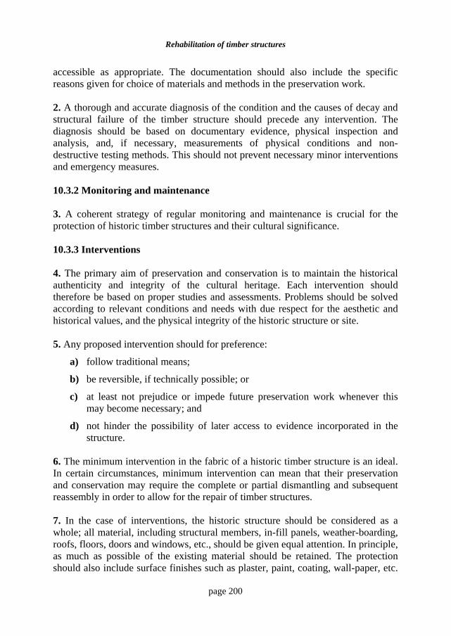
Rehabilitation of timber structures
page 200
accessible as appropriate. The documentation should also include the specific reasons given for choice of materials and methods in the preservation work. 2. A thorough and accurate diagnosis of the condition and the causes of decay and structural failure of the timber structure should precede any intervention. The diagnosis should be based on documentary evidence, physical inspection and analysis, and, if necessary, measurements of physical conditions and non-destructive testing methods. This should not prevent necessary minor interventions and emergency measures. 10.3.2 Monitoring and maintenance 3. A coherent strategy of regular monitoring and maintenance is crucial for the protection of historic timber structures and their cultural significance. 10.3.3 Interventions 4. The primary aim of preservation and conservation is to maintain the historical authenticity and integrity of the cultural heritage. Each intervention should therefore be based on proper studies and assessments. Problems should be solved according to relevant conditions and needs with due respect for the aesthetic and historical values, and the physical integrity of the historic structure or site. 5. Any proposed intervention should for preference:
a) follow traditional means;
b) be reversible, if technically possible; or
c) at least not prejudice or impede future preservation work whenever this may become necessary; and
d) not hinder the possibility of later access to evidence incorporated in the structure.
6. The minimum intervention in the fabric of a historic timber structure is an ideal. In certain circumstances, minimum intervention can mean that their preservation and conservation may require the complete or partial dismantling and subsequent reassembly in order to allow for the repair of timber structures. 7. In the case of interventions, the historic structure should be considered as a whole; all material, including structural members, in-fill panels, weather-boarding, roofs, floors, doors and windows, etc., should be given equal attention. In principle, as much as possible of the existing material should be retained. The protection should also include surface finishes such as plaster, paint, coating, wall-paper, etc.
Building Rehabilitation
page 201
If it is necessary to renew or replace surface finishes, the original materials, techniques and textures should be duplicated as far as possible. 8. The aim of restoration is to conserve the historic structure and its load bearing function and to reveal its cultural values by improving the legibility of its historical integrity, its earlier state and design within the limits of existing historic material evidence, as indicated in articles 9 – 13 of the Venice Charter. Removed members and other components of the historic structure should be catalogued, and characteristic samples kept in permanent storage as part of the documentation. 10.3.4 Repair and replacement 9. In the repair of a historic structure, replacement timber can be used with due respect to relevant historical and aesthetical values, and where it is an appropriate response to the need to replace decayed or damaged members or their parts, or to the requirements of restoration. New members or parts of members should be made of the same species of wood with the same, or, if appropriate, with better, grading as in the members being replaced. Where possible, this should also include similar natural characteristics. The moisture content and other physical characteristics of the replacement timber should be compatible with the existing structure. Craftsmanship and construction technology, including the use of dressing tools or machinery, should, where possible, correspond with those used originally. Nails and other secondary materials should, where appropriate, duplicate the originals. If a part of a member is replaced, traditional woodwork joints should, if appropriate and compatible with structural requirements, be used to splice the new and the existing part. 10. It should be accepted that new members or parts of members will be distinguishable from the existing ones. To copy the natural decay or deformation of the replaced members or parts is not desirable. Appropriate traditional or well-tested modern methods may be used to match the colouring of the old and the new with due regard that this will not harm or degrade the surface of the wooden member. 11. New members or parts of members should be discretely marked, by carving, by marks burnt into the wood or by other methods, so that they can be identified later. 10.3.5 Historic forest reserves 12. The establishment and protection of forest or woodland reserves where appropriate timber can be obtained for the preservation and repair of historic timber structures should be encouraged. Institutions responsible for the preservation and
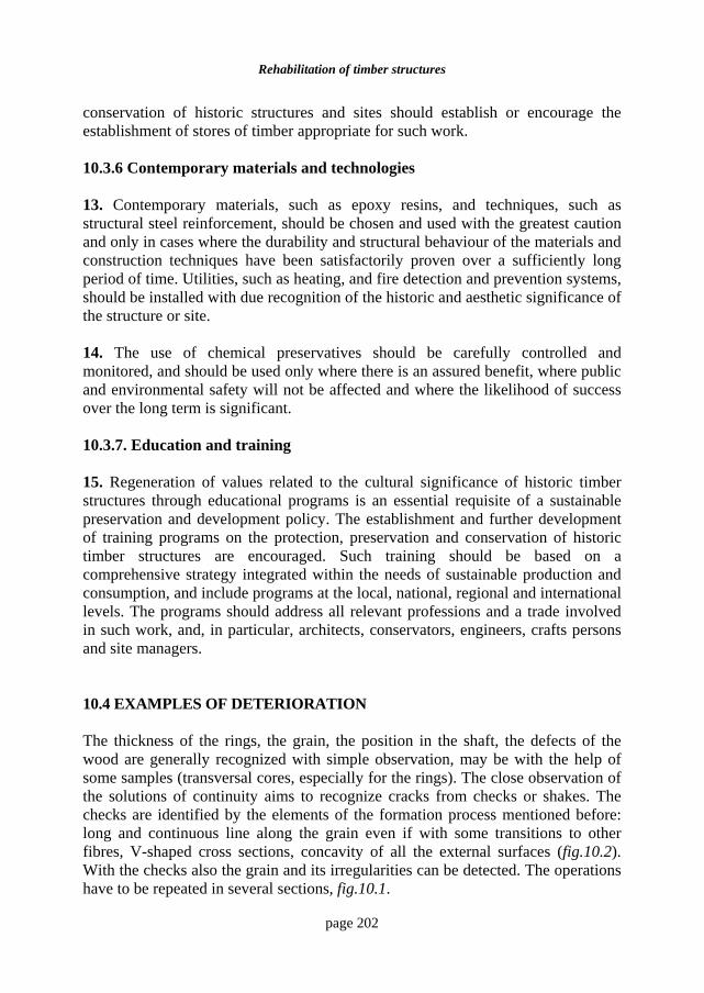
Rehabilitation of timber structures
page 202
conservation of historic structures and sites should establish or encourage the establishment of stores of timber appropriate for such work. 10.3.6 Contemporary materials and technologies 13. Contemporary materials, such as epoxy resins, and techniques, such as structural steel reinforcement, should be chosen and used with the greatest caution and only in cases where the durability and structural behaviour of the materials and construction techniques have been satisfactorily proven over a sufficiently long period of time. Utilities, such as heating, and fire detection and prevention systems, should be installed with due recognition of the historic and aesthetic significance of the structure or site. 14. The use of chemical preservatives should be carefully controlled and monitored, and should be used only where there is an assured benefit, where public and environmental safety will not be affected and where the likelihood of success over the long term is significant. 10.3.7. Education and training 15. Regeneration of values related to the cultural significance of historic timber structures through educational programs is an essential requisite of a sustainable preservation and development policy. The establishment and further development of training programs on the protection, preservation and conservation of historic timber structures are encouraged. Such training should be based on a comprehensive strategy integrated within the needs of sustainable production and consumption, and include programs at the local, national, regional and international levels. The programs should address all relevant professions and a trade involved in such work, and, in particular, architects, conservators, engineers, crafts persons and site managers. 10.4 EXAMPLES OF DETERIORATION The thickness of the rings, the grain, the position in the shaft, the defects of the wood are generally recognized with simple observation, may be with the help of some samples (transversal cores, especially for the rings). The close observation of the solutions of continuity aims to recognize cracks from checks or shakes. The checks are identified by the elements of the formation process mentioned before: long and continuous line along the grain even if with some transitions to other fibres, V-shaped cross sections, concavity of all the external surfaces (fig.10.2). With the checks also the grain and its irregularities can be detected. The operations have to be repeated in several sections, fig.10.1.
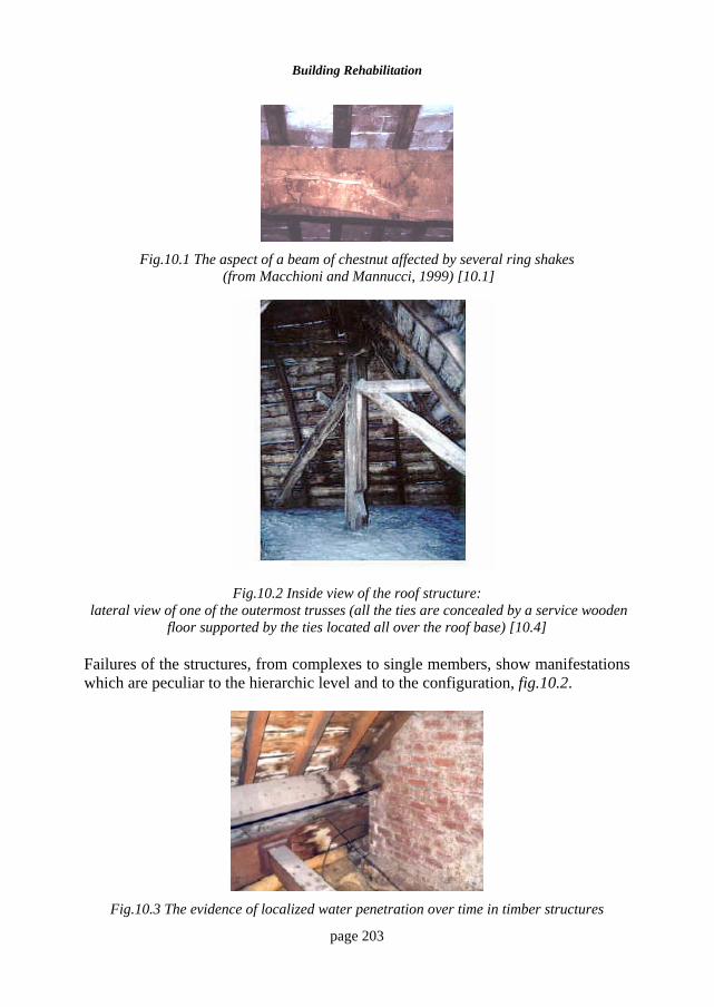
Building Rehabilitation
page 203
Fig.10.1 The aspect of a beam of chestnut affected by several ring shakes
(from Macchioni and Mannucci, 1999) [10.1]
Fig.10.2 Inside view of the roof structure: lateral view of one of the outermost trusses (all the ties are concealed by a service wooden
floor supported by the ties located all over the roof base) [10.4] Failures of the structures, from complexes to single members, show manifestations which are peculiar to the hierarchic level and to the configuration, fig.10.2.
Fig.10.3 The evidence of localized water penetration over time in timber structures
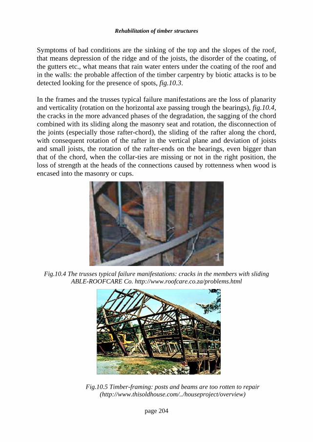
Rehabilitation of timber structures
page 204
Symptoms of bad conditions are the sinking of the top and the slopes of the roof, that means depression of the ridge and of the joists, the disorder of the coating, of the gutters etc., what means that rain water enters under the coating of the roof and in the walls: the probable affection of the timber carpentry by biotic attacks is to be detected looking for the presence of spots, fig.10.3.
In the frames and the trusses typical failure manifestations are the loss of planarity and verticality (rotation on the horizontal axe passing trough the bearings), fig.10.4, the cracks in the more advanced phases of the degradation, the sagging of the chord combined with its sliding along the masonry seat and rotation, the disconnection of the joints (especially those rafter-chord), the sliding of the rafter along the chord, with consequent rotation of the rafter in the vertical plane and deviation of joists and small joists, the rotation of the rafter-ends on the bearings, even bigger than that of the chord, when the collar-ties are missing or not in the right position, the loss of strength at the heads of the connections caused by rottenness when wood is encased into the masonry or cups.
Fig.10.4 The trusses typical failure manifestations: cracks in the members with sliding
ABLE-ROOFCARE Co. http://www.roofcare.co.za/problems.html
Fig.10.5 Timber-framing: posts and beams are too rotten to repair
(http://www.thisoldhouse.com/../houseproject/overview)
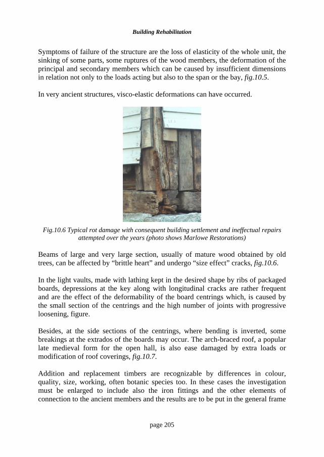
Building Rehabilitation
page 205
Symptoms of failure of the structure are the loss of elasticity of the whole unit, the sinking of some parts, some ruptures of the wood members, the deformation of the principal and secondary members which can be caused by insufficient dimensions in relation not only to the loads acting but also to the span or the bay, fig.10.5. In very ancient structures, visco-elastic deformations can have occurred.
Fig.10.6 Typical rot damage with consequent building settlement and ineffectual repairs
attempted over the years (photo shows Marlowe Restorations)
Beams of large and very large section, usually of mature wood obtained by old trees, can be affected by “brittle heart” and undergo “size effect” cracks, fig.10.6.
In the light vaults, made with lathing kept in the desired shape by ribs of packaged boards, depressions at the key along with longitudinal cracks are rather frequent and are the effect of the deformability of the board centrings which, is caused by the small section of the centrings and the high number of joints with progressive loosening, figure. Besides, at the side sections of the centrings, where bending is inverted, some breakings at the extrados of the boards may occur. The arch-braced roof, a popular late medieval form for the open hall, is also ease damaged by extra loads or modification of roof coverings, fig.10.7. Addition and replacement timbers are recognizable by differences in colour, quality, size, working, often botanic species too. In these cases the investigation must be enlarged to include also the iron fittings and the other elements of connection to the ancient members and the results are to be put in the general frame
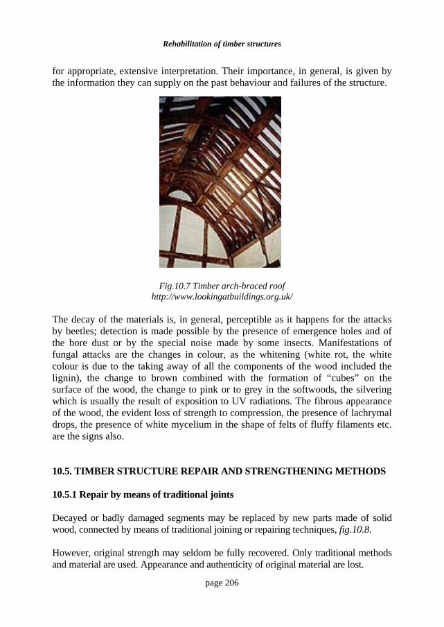
Rehabilitation of timber structures
page 206
for appropriate, extensive interpretation. Their importance, in general, is given by the information they can supply on the past behaviour and failures of the structure.
Fig.10.7 Timber arch-braced roof
http://www.lookingatbuildings.org.uk/
The decay of the materials is, in general, perceptible as it happens for the attacks by beetles; detection is made possible by the presence of emergence holes and of the bore dust or by the special noise made by some insects. Manifestations of fungal attacks are the changes in colour, as the whitening (white rot, the white colour is due to the taking away of all the components of the wood included the lignin), the change to brown combined with the formation of “cubes” on the surface of the wood, the change to pink or to grey in the softwoods, the silvering which is usually the result of exposition to UV radiations. The fibrous appearance of the wood, the evident loss of strength to compression, the presence of lachrymal drops, the presence of white mycelium in the shape of felts of fluffy filaments etc. are the signs also. 10.5. TIMBER STRUCTURE REPAIR AND STRENGTHENING METHODS 10.5.1 Repair by means of traditional joints Decayed or badly damaged segments may be replaced by new parts made of solid wood, connected by means of traditional joining or repairing techniques, fig.10.8. However, original strength may seldom be fully recovered. Only traditional methods and material are used. Appearance and authenticity of original material are lost.
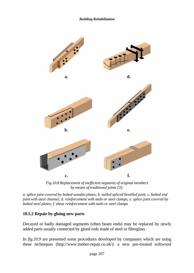
Building Rehabilitation
page 207
a.
d.
b.
e.
c.
f.
Fig.10.8 Replacement of inefficient segments of original members by means of traditional joints [3]:
a. splice joint covered by bolted wooden plates; b. nailed spliced bevelled joint; c. bolted end joint with steel channel; d. reinforcement with nails or steel clamps; e. splice joint covered by bolted steel plates; f. shear reinforcement with nails or steel clamps 10.5.2 Repair by gluing new parts Decayed or badly damaged segments (often beam ends) may be replaced by newly added parts usually connected by glued rods made of steel or fibreglass. In fig.10.9 are presented some procedures developed by companies which are using these techniques (http://www.timber-repair.co.uk/): a new pre-treated softwood
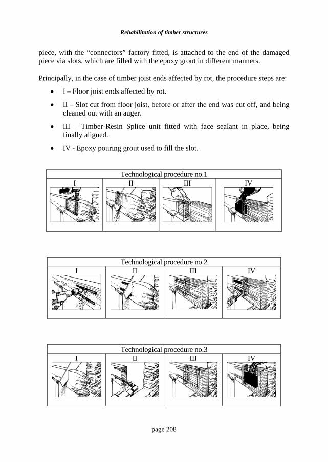
Rehabilitation of timber structures
page 208
piece, with the “connectors” factory fitted, is attached to the end of the damaged piece via slots, which are filled with the epoxy grout in different manners. Principally, in the case of timber joist ends affected by rot, the procedure steps are:
• I – Floor joist ends affected by rot.
• II – Slot cut from floor joist, before or after the end was cut off, and being cleaned out with an auger.
• III – Timber-Resin Splice unit fitted with face sealant in place, being finally aligned.
• IV - Epoxy pouring grout used to fill the slot.
Technological procedure no.1 I II III IV
Technological procedure no.2 I
II
III
IV
Technological procedure no.3 I
II
III
IV
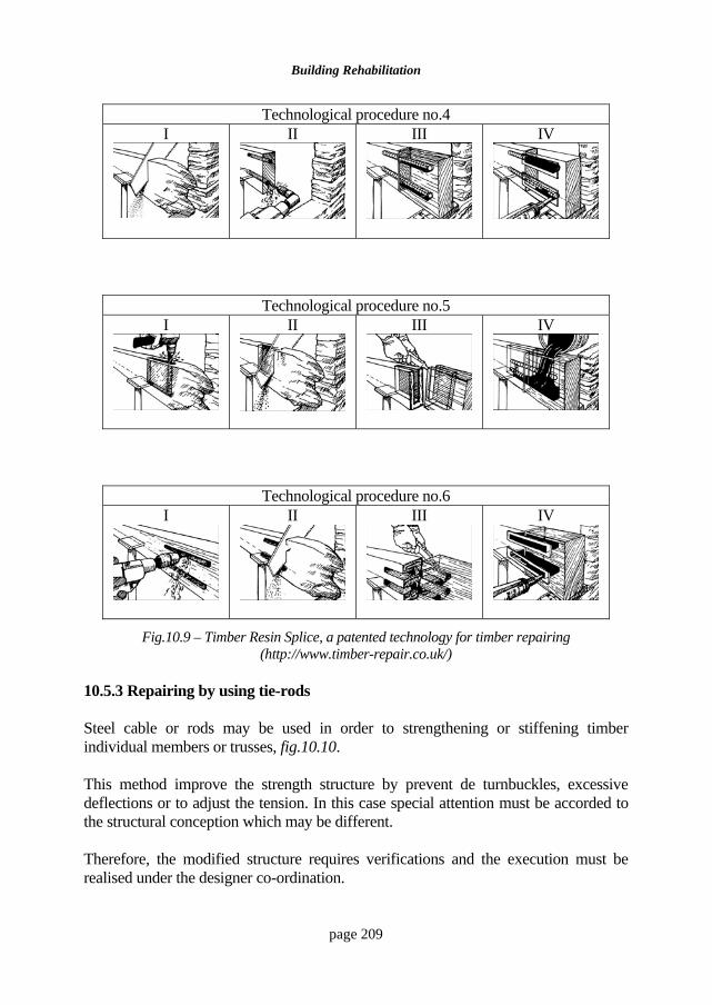
Building Rehabilitation
page 209
Technological procedure no.4 I
II
III
IV
Technological procedure no.5 I
II
III
IV
Technological procedure no.6 I
II
III
IV
Fig.10.9 – Timber Resin Splice, a patented technology for timber repairing (http://www.timber-repair.co.uk/)
10.5.3 Repairing by using tie-rods Steel cable or rods may be used in order to strengthening or stiffening timber individual members or trusses, fig.10.10. This method improve the strength structure by prevent de turnbuckles, excessive deflections or to adjust the tension. In this case special attention must be accorded to the structural conception which may be different. Therefore, the modified structure requires verifications and the execution must be realised under the designer co-ordination.
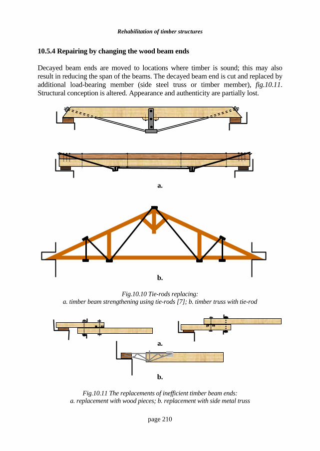
Rehabilitation of timber structures
page 210
10.5.4 Repairing by changing the wood beam ends Decayed beam ends are moved to locations where timber is sound; this may also result in reducing the span of the beams. The decayed beam end is cut and replaced by additional load-bearing member (side steel truss or timber member), fig.10.11. Structural conception is altered. Appearance and authenticity are partially lost.
a.
b.
Fig.10.10 Tie-rods replacing: a. timber beam strengthening using tie-rods [7]; b. timber truss with tie-rod
a.
b.
Fig.10.11 The replacements of inefficient timber beam ends: a. replacement with wood pieces; b. replacement with side metal truss
Building Rehabilitation
page 211
10.6 MAINTENANCE AND CONSERVATION MEASURES Maintenance work should always carry out with a view to the continued conservation of the structure. The action of potential deterioration agents should be anticipated and prevented [10.3]. Moisture, in its forms and origins, should be considered a major threat to the conservation of timber structures, including those which have undergone recent or earlier repair work. Special case should be taken to ensure the proper execution of recommended repair or prevention works. BIBLIOGRAPHY
10.1 Tampone G. - Acquaintance of the ancient timber structures in Historical Constructions, P.B. Lourenço, P. Roca (Eds.), Guimarães, 2001, 117.
10.2 International Council and Monuments and Sites, Documentation Centres UNESCO-ICOMOS – Principles for the preservation of Historic Timber Structures (1999), http://www.international.icomos.org/
10.3 Blass H.J., Aune P., Choo B.S., et all, editors - EUROCODE 5 : Timber Engineering-Step 2, Design-Details and Structural Systems, Centrum Hout, Netherlands, 1995.
10.4 Lauriola M., Mannucci M., Oschi M., Macchioni N. - A reliable inspection procedure of existing timber structures: the case of Guarini's Towers roofs - Racconigi Castle (Italy), http://www.ndt.net/article/wcndt00/papers/idn.
10.5 Macchioni N., Mannucci M. - Inspection techniques for ancient wooden structures: state of the art and research needs. 6th International Conference on "Non Destructive Testing and Mycroanalysis for the Diagnostics and Conservation of Cultural and Environmental Heritage" (ART'99), Rome 17-19 May 1999, 2155-2165.
10.6 Macchioni N., Mannucci M., Zanuttini R. - Non-destructive evaluation of ancient wooden structures. 2nd International Congress on "Science and technology for the safeguard of cultural heritage in the mediterranean basin", Paris 5-9 July 1999, 161.
10.7 Arsenie G., Voiculescu M., Ionascu M. – Solutii de consolidare a constructiilor avariate de cutremure, Editura Tehnica, Bucuresti, 1997.
10.8 Isopescu Dorina – Timber Structures, Ed. “Gh. Asachi”, Iasi, 2002.
page 212
11 HYGROTHERMAL REHABILITATION
OF BUILDINGS 11.1 GENERAL ASPECTS In order to ensure the best temperature values inside the buildings in cold periods thermal energy is required to compensate for the heat loss through the closure elements, dependent on their insulating capacity. The application of efficient solutions to limit heat loss during the exploitation of buildings requires knowledge of heat transfer ways from rooms towards the outside during cold seasons , as well as of the weight of the attached energy of these ways in the overall heat loss. In the case of ordinary buildings, heat losses towards the exterior in winter are released in the following proportions:
• 40...50% by air exchange between the rooms and the exterior,
• 20...25% through the opaque zones of external walls,
• 10...25% through windows, skylights and external doors,
• 5...10% through the roofing structure,
• 5...10% through the basement floor toward the ground. This repartition depends on the form, structure and plane sizes of building, the number of storeys, the surface and structure of the envelope, the size and thermal insulation qualities of different component zones, as well as on the intensity of air exchange between rooms and environment. There must be a direct connection between the thermal insulation qualities of building elements and energy consumption for heating in order to achieve thermal comfort in rooms [11.1], [11.2]:
• a lower thermal insulation capacity of closure elements requires higher thermal energy consumption in exploitation to maintain the hygrothermal

Building Rehabilitation
page 213
parameters of interior climate at the level of comfort values; inversely, a higher thermal insulation degree of building envelope allows the obtainance of the same thermal effects with lower energy consumption;
• the higher the energy reserves, the more insulation qualities of envelope may be diminished, the heating system having the dominant role; inversely, the less energy reserves available for various reasons, the more decrease in heat loss is required by ensuring higher thermal insulation qualities of external closure elements.
The option for one or the other of the two variants is first determined by economical, energetical and environment protection reasons, as well as by the effect of the connection between the physical factors that characterize the interior of rooms and comfort, along with the inherent subjectivity in estimating the microclimate conditions by various categories of people. In the case of new buildings, the assurance of thermal comfort in rooms using reduced energy consumption can be achieved quite easily by means of a correct design, based on technical prescriptions that stipulate high standardized values for the thermal protection of envelope components in order to provide them with an adequate level of thermal insulation , as early as the initial design phases. Old buildings, which suffered a diminution of thermal insulation qualities of external protection elements during exploitation, because of cumulated cyclical action of some environmental factors (high temperature and moisture variations, solar radiation, freeze-thaw phenomenon etc.) as well as of improper exploitation conditions, are generally characterized by thermal insulation capacity below thermal comfort requirements. In the case of old buildings, there is also the problem of the low efficiency of their physically and morally worn out heating systems, which are often unsuitable for modernization. Besides that, the thermophysical degradations and depreciation of installations conveying the thermal agent determine excessively high heat losses on the route in cold weather. These problems may be solved by applying some adequate technical actions, meant to increase the thermal insulation capacity of existing envelopes, or at least that of the main structural elements with inadequate thermal qualities. This is what is called thermal rehabilitation, a radical technical intervention which must take into account all the ways in which the building loses heat, both toward exterior and interior unheated spaces. Simultaneously with heat loss diminution it is important to have in view some measures to fight the negative effects due to
Hydrothermal rehabilitation of buildings
page 214
vapour diffusion trough closure elements, mainly condensation. That leads to the hygrothermal rehabilitation of old buildings. If there are also other physical aspect which may be solved along with the interventions for supplementary thermal protection (e.g. the diminution of excessive air change, the improvement of natural lighting etc.), and require some specific interventions in order to ensure the overall comfort and hygiene conditions in the existing buildings, the notion of thermophysical rehabilitation can be defined. Besides the thermal component of hygrothermal rehabilitation, ventilation rehabilitation can also be mentioned, that is the rationalization of air exchange between the rooms and the exterior to ensure normal hygiene and sanitary conditions, and the least possible heat losses from rooms in cold periods [11.2], [11.3]. Thus, if the heat lost through the closure elements is low, the amount of heat losses due to air exchange increases. However, they must be accepted up to the level corresponding to the minimum hygiene and health requirements. Consequently, if the thermal qualities of closure elements can be improved up to very high performance levels to diminish heat transmission, as regards the way of air exchange it is necessary to limit the air flow decrease for hygiene and sanitary reasons. From a hygrothermal point of view this means a minimum flow of energy losses required, which must be accepted unconditionally. Even though the opaque closure elements may be ensured high performances of thermal resistance, the increase in insulation performances of some component zones (like glazed elements) is limited. These limitations are determined by their functional role as well as by the thermal qualities of materials utilized. If the interventions to improve the thermal insulation are not applied to the entire envelope of the building, the partial rehabilitation results in the change of the repartition of heat losses through the component zones of the closure elements and through the air exchange between rooms and the exterior, in favour of the hygrothermally untreated or insufficiently treated ways, who thus become preferential ways for thermal transmission. Consequently, it is necessary to approach and treat all the ways the building loses heat in winter very seriously, even if a first analysis points that some areas on the envelope are less involved in thermal exchange with the environment than others, which are thermally less effective and thus considered to be more important. The overall thermo-physical rehabilitation presupposes high consumption of efficient materials, highly qualified labour, long execution duration as well as a
Building Rehabilitation
page 215
considerable financial effort. That is why such an action performed on a large scale to all hygrothermally damaged buildings, or at least to the most important ones is very difficult to carry out in unfavourable economic conditions.In this case, it is recommended that the buildings whose exploitation is absolutely necessary should take priority over the others. Another rational thermal rehabilitation manner of a great number of buildings is to phase the works on categories of envelope elements in order of degradation condition and their importance within the assemblyso that the building could continue to be exploited in adequate conditions. Temperature represents the main stimulant for the thermal regulator system of the human body, and influences other sides of hygrothermal behaviour as well as the energy consumption during exploitation. Therefore, the thermal aspect will be further dealt with in detail. 11.2 THE NEED FOR THERMO-PHYSICAL REHABILITATION After a certain exploitation period, the hygrothermal rehabilitation of some elements making the envelope of the buildings with thermal comfort problems in cold periods may become necessary due to:
i. the decrease in thermal insulation qualities of component materials;
ii. the increase in exigencies level concerning the hygrothermal comfort;
iii. the increase in exigencies concerning the thermal insulation degree;
iv. the modernization of some existing buildings. 11.2.1 The decrease in thermal insulation qualities of materials During exploitation, the elements making the building envelope, particularly the exterior walls and the roofs, are subjected to the cyclic action of environmental factors, as well as of some microclimatic factors in the rooms. These actions determine the diminution of thermal characteristics of the component materials in time and implicitly of the thermal insulation degree of elements. The climatic factors that determine the degradation of materials in time are:
• temperature variations,
• recurrent frost-thaw,
• infiltration of rainfall water,
Hydrothermal rehabilitation of buildings
page 216
• solar radiations. In addition to these climatic factors, certain acids, such as sulfuric acid, the carbonic acid and the nitric acid, which are formed from some pollutant substances in combination with water vapors in the air also have destructive chemical effects. Degradation may also be caused by some interior microclimatic factors like the condensation of exfiltrated water vapors through the exterior building elements in cold periods. The water accumulated in materials determines the increase in their thermal conductivity , which combined with the low temperatures gradually leads to the depreciation of materials with capillary-porous structure, due to the repeated frost-thaw phenomenon. Other less important factors determining the diminution of the qualities of thermal insulation are:
• the vibrations during the earthquakes and those caused by the wind,
• the dynamic loading of exploitation, which can settle the materials,
• the action of rodents and microorganisms, which damage some organic insulation materials.
11.2.2 The increase in exigencies concerning the hygrothermal comfort After a certain period of exploitation, or sometimes because of some changes occurred in the destination or functional requirements of the building, the level of exigencies concerning the hygrothermal comfort in rooms may increase. In order to satisfy the increased requirements of hygrothermal comfort, two types of interventions meant to reach the optimal values for the physical parameters of the microclimate in rooms may be applied:
• supplementary energy input necessary for heating the rooms,
• increasing the thermal insulation qualities of the closure elements. At present the increase in energy consumption to heat the rooms in buildings is not possible on a large scale.The only viable solution remains the hygrothermal rehabilitation by technical measures meant to improve the thermal insulation qualities of the building elements forming the envelope. 11.2.3 The increase in exigencies concerning the thermal insulation degree The increase in exigencies concerning the thermal insulation of the elements of the envelope has become necessary as a result of the world energetic crisis, as well as
Building Rehabilitation
page 217
of the recent preoccupations to reduce the air pollution caused by classic fuel burning. In the advanced countries, the tendency to rationalize the energy consumption requires that the closure elements of buildings should be apparently thermally oversized, For these elements, values like 3-4 m2K/W for thermal resistance are very frequent. In Romania, most buildings in exploitation were built betwwen 1960 and 1980. The closure elements of these buildings had very low values of standardized thermal resistance, whose adoption was based on economic criteria that seem completely irrational nowadays. The current wall systems applied to these buildings contain large prefabs panels or monolith reinforced concrete diaphragms, with an insulating core made of less thermally efficient water-sensitive materials (cellular concrete, mineral wool, lightweight concrete etc.), with extended networks of thermal bridges, made of reinforced concrete ribs. These types of walls are thermally inadequate nowadays, as they allow excessive heat losses, which are economically unacceptable. The low level of thermal insulation of the closure elements determines extremely high energy consumption for heating the rooms as well as considerable decrease in hygrothermal comfort inside rooms in cold periods. The tendency towards increasing the comfort level by consuming the lowest amount of energy possible will certainly determine the alignment to the practice of the developed countries, which proved to be rational and efficient. Therefore, some increased standardized values of thermal insulation may be foreseen for Romania as well, that is up to:
• 2,5...3 m2K/W – for the opaque parts of exterior walls and
• 3,5...5 m2K/W – for flat-roofs, values that are 2...3 times higher than the current standardized values. This orientation will further result in the execution of new buildings with low energy consumption in exploitation and the appliance of thermal rehabilitation measures to the old buildings, which will ensure the diminution of heat losses up to an acceptable level, satisfying the requirements of thermal comfort as well. 11.2.4 The modernization of some existing buildings
The necessity to modernize some existing older buildings, determined by various reasons mentioned below, may also constitute an opportunity for the application of
Hydrothermal rehabilitation of buildings
page 218
some thermal rehabilitation measures. Numerous buildings, particularly those that have been exploited for a log time, have suffered from the negative effects of some earthquakes, some environmental and inner microclimatic factors, as well as alterations occasioned by repairs, maintenance, restoration works etc., which have affected their mechanical strength and insulation capacity. At the same time, functional reasons may determine the need for new division and distribution of rooms, floor addition, extension etc., corresponding to new exigencies or functions. In order to ensure the harmonious framing within a modern building assembly, some older buildings may require aesthetic rehabilitation works, meaning numerous other technical operations besides finishing works. In these cases, the suitability of hygrothermal rehabilitation works on the closure elements of the existing buildings is also sustained by the following reasons:
• the structural and auxiliary works required are not different from those corresponding to the main objective, except in some special situations,
• they may coincide to a large extent with the works destined to improve the aesthetic aspect of the building, with minimal specific interventions,
• the increase in overall cost due to the supplementary rehabilitation works is reasonable, as it generally includes only the cost of the thermal insulation,
• they may also physically and mechanically protect other closure elements, whch have been rehabilitated for other reasons.
Normally, even if at a certain point the financial effort seems difficult to accept, it is necessary that along with the thermo-physical rehabilitation general technical revisions should be carried out. If required, improvement works should be performed on structural elements and installations, particularly on those that will to be concealed by thermo-physical rehabilitation works. The general thermal rehabilitation works on the existing older buildings are usually time-consuming and expensive. Therefore, they should be preceded by a minute technical and economical analysis. For the same reasons it seems rational to combine the thermo-physical rehabilitation with other rehabilitation works, such as mechanical, functional, architectural, installation rehabilitation etc.
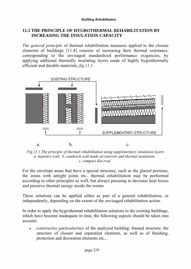
Building Rehabilitation
page 219
11.3 THE PRINCIPLE OF HYGROTHERMAL REHABILITATION BY INCREASING THE INSULATION CAPACITY
The general principle of thermal rehabilitation measures applied to the closure elements of buildings [11.4] consists of increasing their thermal resistance, corresponding to the envisaged standardized performance exigencies, by applying addtional thermally insulating layers made of highly hygrothermally efficient and durable materials, fig.11.1.
a. b. c.
Fig.11.1 The principle of thermal rehabilitation using supplementary insulation layers a. masonry wall, b. sandwich wall made of concrete and thermal insulation,
c. compact flat-roof
For the envelope areas that have a special structure, such as the glazed portions, the zones with untight joints etc., thermal rehabilitation may be performed according to other principles as well, but always pursuing to decrease heat losses and preserve thermal energy inside the rooms. These solutions can be applied either as part of a general rehabilitation, or independently, depending on the extent of the envisaged rehabilitation action. In order to apply the hygrothermal rehabilitation solutions to the existing buildings, which have become inadequate in time, the following aspects should be taken into account:
• constructive particularities of the analyzed building: framed structure, the structure of closure and separation elements, as well as of finishing, protection and decoration elements etc.,
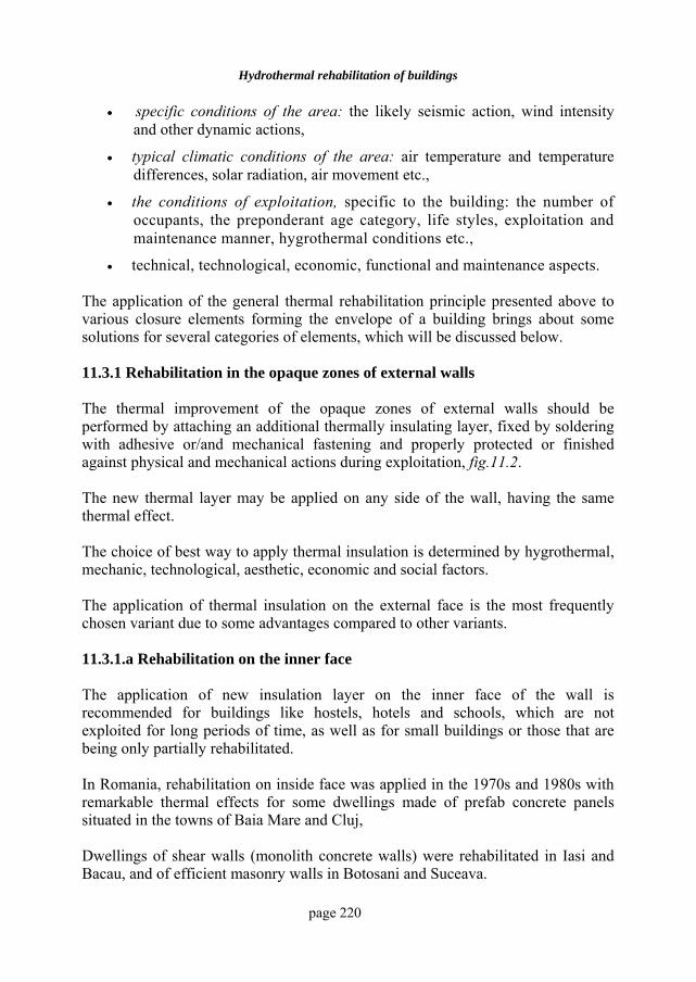
Hydrothermal rehabilitation of buildings
page 220
• specific conditions of the area: the likely seismic action, wind intensity and other dynamic actions,
• typical climatic conditions of the area: air temperature and temperature differences, solar radiation, air movement etc.,
• the conditions of exploitation, specific to the building: the number of occupants, the preponderant age category, life styles, exploitation and maintenance manner, hygrothermal conditions etc.,
• technical, technological, economic, functional and maintenance aspects. The application of the general thermal rehabilitation principle presented above to various closure elements forming the envelope of a building brings about some solutions for several categories of elements, which will be discussed below. 11.3.1 Rehabilitation in the opaque zones of external walls The thermal improvement of the opaque zones of external walls should be performed by attaching an additional thermally insulating layer, fixed by soldering with adhesive or/and mechanical fastening and properly protected or finished against physical and mechanical actions during exploitation, fig.11.2. The new thermal layer may be applied on any side of the wall, having the same thermal effect. The choice of best way to apply thermal insulation is determined by hygrothermal, mechanic, technological, aesthetic, economic and social factors. The application of thermal insulation on the external face is the most frequently chosen variant due to some advantages compared to other variants.
11.3.1.a Rehabilitation on the inner face The application of new insulation layer on the inner face of the wall is recommended for buildings like hostels, hotels and schools, which are not exploited for long periods of time, as well as for small buildings or those that are being only partially rehabilitated. In Romania, rehabilitation on inside face was applied in the 1970s and 1980s with remarkable thermal effects for some dwellings made of prefab concrete panels situated in the towns of Baia Mare and Cluj, Dwellings of shear walls (monolith concrete walls) were rehabilitated in Iasi and Bacau, and of efficient masonry walls in Botosani and Suceava.
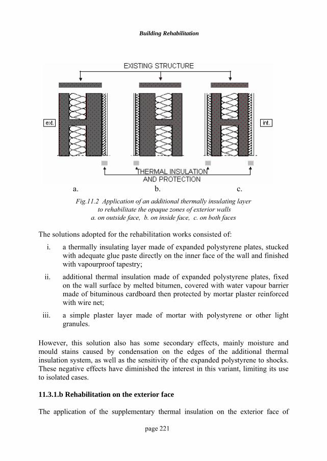
Building Rehabilitation
page 221
a. b. c. Fig.11.2 Application of an additional thermally insulating layer
to rehabilitate the opaque zones of exterior walls a. on outside face, b. on inside face, c. on both faces
The solutions adopted for the rehabilitation works consisted of:
i. a thermally insulating layer made of expanded polystyrene plates, stucked with adequate glue paste directly on the inner face of the wall and finished with vapourproof tapestry;
ii. additional thermal insulation made of expanded polystyrene plates, fixed on the wall surface by melted bitumen, covered with water vapour barrier made of bituminous cardboard then protected by mortar plaster reinforced with wire net;
iii. a simple plaster layer made of mortar with polystyrene or other light granules.
However, this solution also has some secondary effects, mainly moisture and mould stains caused by condensation on the edges of the additional thermal insulation system, as well as the sensitivity of the expanded polystyrene to shocks. These negative effects have diminished the interest in this variant, limiting its use to isolated cases. 11.3.1.b Rehabilitation on the exterior face The application of the supplementary thermal insulation on the exterior face of
Hydrothermal rehabilitation of buildings
page 222
exterior walls, fig.11.2.b, is the most preferred solution due to its significant hygrothermal, technological and social advantages. It is suitable mainly for blocks of flats, institutions with offices, hospitals, hostels etc., characterized by monotonous façades and large surfaces. 11.3.1.c Rehabilitation on both surfaces The application of the supplementary thermally insulating layer on both surfaces of the walls, fig.11.2.c, may be a good solution when the additional thermal resistance needed requires thick thermal insulation. In this case technical, economic and protection reasons make the application of insulation on one side of the wall seem unreasonable. Another case would be when thermal insulation has already been applied to one side.
11.3.2 Rehabilitation in the glazed portions of the exterior walls Thermal transmission in the glazed zones of the exterior walls may be diminished by decreasing the direct heat transmission corresponding to the transparent portions and the opaque elements, as well as by reducing the intensity of air exchange through the untight joints of joinery [11.6]. 11.3.2.a Thermal rehabilitation of transparent zones The thermal improvement of the transparent zones of exterior walls is absolutely necessary as part of the general rehabilitation of a building, since a great amount of heat is lost through these zones (about 25%). The possibilities of improving the hygrothermal performances of external glazed joinery are still limited and relatively reduced compared to the opaque zones of walls due to their functional and structural particularity. For ordinary windows, the best results can be obtained by increasing the number of thin air layers (1...5 cm), closed between the glass panes, on the existing window frames or on supplementary frames, as thickening the glass panes on the existing frames does not produce a significant thermal effect. Although the thermal resistance of the glazed zone increases by at least 40% for only one additional air layer, the application of thermal rehabilitation by using more supplementary window panes is limited because of both increase in window weight and the difficult access between the glasses, which prevents maintenance. An advantageous variant from the economic and technical viewpoint in winter time only is obtained by sticking or mechanically fastening thin transparent sheets made of cellophane, polyethylene etc on the existing jambs, which, together with the window panes, entrap some air spaces, thus doubling the thermal insulation
Building Rehabilitation
page 223
capacity of ordinary windows. In warm periods, the transparent sheets can be removed or rolled, enabling the normal maintenance of the glass panes. 11.3.2.b The thermal rehabilitation of frames The thermal rehabilitation of frames is more difficult to do to ordinary windows, and the effects that could be obtained by applying some technical solutions are reduced and are not really worth the effort. Theoretically, the thermal rehabilitation of these components would consist of attaching the thermal insulation material. As the joinery of older buildings often presents degradations and deformations caused by the utilization manner, as well as by environmental factors, their rehabilitation must also take into account the decrease in air exchange through joints. Therefore, the thermal rehabilitation of a building must also include technical measures meant to decrease the air exchange through the leakness of the windows, which is usually bigger than hygiene conditions require because of the degradations of the tightening systems and the wear of the closure systems.
The existing joinery needs overhauling to remedy the deformed or degraded elements. They are repaired by: completion wits wood slates, replacing some components, completing or replacing the affected tightening systems (putty cordons, slats, fixing systems and devices) etc. It is also possible to apply some tightening systems without the risk of air exchange diminution below the limit imposed by hygiene requirements. Such systems might be covering slats on the joints; fittings of adhesive bands made of expanded plastic materials or thick textile materials and fixed in the profiles of the jambs; special fittings made of rubber, neopren or other elastic materials etc. 11.3.3 Flat-roof rehabilitation Most buildings requiring thermo-physical rehabilitation works are equipped with compact flat-roofs, which have thermal insulation and bituminous waterproof covering [11.3]. The interventions for rehabilitating these solutions can be applied only to their upper part, partly because of economic reasons. 11.3.3.a Flat-roofs rehabilitation by thorough replacement This rehabilitation consists of replacing the entire structure on the last floor with a new structure, which must also contain a thermally insulating layer, whose dimensions are established in accordance with the thermal protection requirements. The solution is more expensive but it is necessary if the old structure is very damaged or permits the accumulation of water produced by condensation or infiltrations, with intense and frequent unfavourable effects on the last floor.
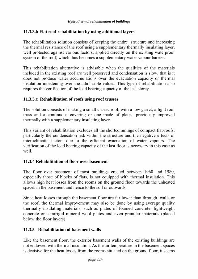
Hydrothermal rehabilitation of buildings
page 224
11.3.3.b Flat roof rehabilitation by using additional layers The rehabilitation solution consists of keeping the entire structure and increasing the thermal resistance of the roof using a supplementary thermally insulating layer, well protected against various factors, applied directly on the existing waterproof system of the roof, which thus becomes a supplementary water vapour barrier. This rehabilitation alternative is advisable when the qualities of the materials included in the existing roof are well preserved and condensation is slow, that is it does not produce water accumulations over the evacuation capacity or thermal insulation moistening over the admissible values. This type of rehabilitation also requires the verification of the load bearing capacity of the last storey. 11.3.3.c Rehabilitation of roofs using roof trusses The solution consists of making a small classic roof, with a low garret, a light roof truss and a continuous covering or one made of plates, previously improved thermally with a supplementary insulating layer. This variant of rehabilitation excludes all the shortcommings of compact flat-roofs, particularly the condensation risk within the structure and the negative effects of microclimatic factors due to the efficient evacuation of water vapours. The verification of the load bearing capacity of the last floor is necessary in this case as well. 11.3.4 Rehabilitation of floor over basement The floor over basement of most buildings erected between 1960 and 1980, especially those of blocks of flats, is not equipped with thermal insulation. This allows high heat losses from the rooms on the ground floor towards the unheated spaces in the basement and hence to the soil or outwards. Since heat losses through the basement floor are far lower than through walls or the roof, the thermal improvement may also be done by using average quality thermally insulating materials, such as plates of foamed concrete, lightweight concrete or semirigid mineral wool plates and even granular materials (placed below the floor layers). 11.3.5 Rehabilitation of basement walls Like the basement floor, the exterior basement walls of the existing buildings are not endowed with thermal insulation. As the air temperature in the basement spaces is decisive for the heat losses from the rooms situated on the ground floor, it seems
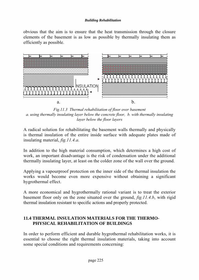
Building Rehabilitation
page 225
obvious that the aim is to ensure that the heat transmission through the closure elements of the basement is as low as possible by thermally insulating them as efficiently as possible.
a. b. Fig.11.3 Thermal rehabilitation of floor over basement
a. using thermally insulating layer below the concrete floor, b. with thermally insulating layer below the floor layers
A radical solution for rehabilitating the basement walls thermally and physically is thermal insulation of the entire inside surface with adequate plates made of insulating material, fig.11.4.a. In addition to the high material consumption, which determines a high cost of work, an important disadvantage is the risk of condensation under the additional thermally insulating layer, at least on the colder zone of the wall over the ground. Applying a vapourproof protection on the inner side of the thermal insulation the works would become even more expensive without obtaining a significant hygrothermal effect. A more economical and hygrothermally rational variant is to treat the exterior basement floor only on the zone situated over the ground, fig.11.4.b, with rigid thermal insulation resistant to specific actions and properly protected. 11.4 THERMAL INSULATION MATERIALS FOR THE THERMO-
PHYSICAL REHABILITATION OF BUILDINGS In order to perform efficient and durable hygrothermal rehabilitation works, it is essential to choose the right thermal insulation materials, taking into account some special conditions and requirements concerning:
Hydrothermal rehabilitation of buildings
page 226
a. b. Fig.11.4. The thermal rehabilitation of basement walls
a. from inside; b. from outside, on the portion over ground
• the thermo-physical qualities and their preservation in time,
• the optimal thickness required for the insulation layers,
• the possibility of safe fastening on the existing structure,
• the finishing and protection systems of the additional thermal insulation. The choice of materials for thermal rehabilitation works must be preceded by a qualitative, technical and economic analysis specific to works performed long after the execution of the building and in different conditions. The main exigencies that should be taken into account when choosing the materials necessary for the thermal rehabilitation works are presented below:
a. thermal conductivity λ should be as low as possible so that the additional thermally insulating layers would be as thin as possible, thus becoming advantageous from both mechanical, technical and economic viewpoint;
b. technical weight should also be as low as possible, so that the load added to the structure by the additional layers would be as small as possible;
c. low sensitivity to water action, to make the necessary hygrothermal protection systems as simple and light as possible;
d. good behaviour to recurrent freeze-thaw, to provide high durability. It is advisable to use closed pore materials or with low water permeability, such
Building Rehabilitation
page 227
as:
• expanded polystyrene,
• foam glass,
• PVC foam etc.
or the compound structures with high tightness to water and vapour like:
• plates with metal sheet faces,
• asbestos-cement plates,
• plastic plates (veral, tbal, rompan, azbopan, polyalpan);
e. high strength and stiffness to bear the loads brought by other layers (the case of flat-roofs), by the protection and finishing systems or the wind (the case of exterior walls), as well as some casual mechanical impacts (the case of the socle) without high deformations;
f. good resistance to fire, without releasing noxious substances and without high deformations to affect their thermo-physical qualities;
g. low sensitivity to temperature variations, meaning very low linear thermal dilatation coefficients (α) to avoid the deformation of the protective elements with negative effects on tightness, stability and aesthetics of rehabilitation systems;
h. convenient cost in accordance with the financial possibilities of the users of old buildings, particularly dwellings.
Since thermal rehabilitation works are performed after long time periods and are quite expensive, the economic aspect would come second when choosing the best materials and solutions. At the same time it is important to know that the inexpensive solutions often bring about important subsequent expenses, as they require more frequent repair and maintainance works later. The necessary thickness of the additional thermally insulating layer will be established by hygrothermal calculus, assuming steady conditions, taking into account the role, the importance and the position of the closure elements to be improved thermally [11.1], [11.5].
These calculations will be made having in view the following parameters:
i. the real values of the overall thermal resistance of the elements to be rehabilitated (R0,ef), which are calculated by taking into account the diminution of the thermal qualities of the component materials in time, due to moisture, temperature variations, settlements etc.
Hydrothermal rehabilitation of buildings
page 228
ii. the stipulated level (Rn) of the overall thermal resistance of elements after the application of the rehabilitation solution, imposed by comfort, energy, economic and environment protection conditions.
11.5 TECHNICAL SOLUTIONS FOR THE THERMO-PHYSICAL
REHABILITATION OF BUILDINGS 11.5.1 The application of additional thermal insulation The application of supplementary thermal insulation, necessary to correct the insulation deficiency, may be achieved in various ways, depending on [11.2], [11.4]:
• the type of thermal insulation material utilised,
• the condition of the elements,
• the exposure of the surface to be treated with insulation (inner or outer),
• the position of the surface of the element (horizontal or vertical),
• the level of the surface finishing
• economic reasons etc. As a rule, the supplementary thermal insulation for rehabilitation may be applied in two ways:
• by sticking directly to the surface of the treated element, if its rigidity/stiffness and the condition of the surface are adequate;
• by fixing on an intermediate structure with supporting role, which may have other functions as well (the solution can be applied especially to the exterior walls of buildings with imperfections and/or which are subjected to various hygrothermal and mechanical actions in time.
11.5.1.a Exterior wall – opaque zone
If the supplementary thermally insulating layer is applied to the inner surface of the wall, the following variants may be regarded:
• by sticking the thermally insulating layers made of light efficient materials (polystyrene, polyurethane, mineral wool etc.) directly on the inner surface of the existing wall, prepared beforehand with a view to ensure the adherence, by means of adhesive paste, e.g. gypsum-aracet or highly adhesive mortar;
• by sticking the additional thermally insulating layers with bitumen or adhesive paste and ensuring them with stainless wire, fixed on steel bolts
Building Rehabilitation
page 229
introduced in the wall beforehand; the finishing may be reinforced plaster on steel net, fixed on the same bolts, or various types of plates;
• by fixing on a wooden slates net, attached to the wall by metal systems (clips, bolts, screws), which prevents the risk of water accumulation due to condensation, and the air space between the thermal insulation and the wall allows vapour migration and their release inside the room, thus enabling the drying.
If the supplementary thermally insulating layer is applied to the outer surface of the wall, fixing may also be done by sticking or mechanical attachment, in the following ways:
• sticking the insulation layer by means of a paste of adhesive mortar (1:0.5:1.5 - cement:aracet:sand), or other adhesive pastes resistant to the actions of environmental factors, where the anchorage of the insulation layer and its protective system with metallic connectors is also recommended
• by mechanical fixing of supplementary thermally insulating layer with metallic elements, which usually sustain the protection system of the insulation layer as well.
11.5.1.b The exterior wall – glazing zone The supplementary glass panes necessary to make some closed unventilated air spaces with thermal insulation qualities may be fastened to the windows in the following way:
• on the existing frames, by using some wooden spacers, fixed with nails and putty or with triangular wooden slats,
• on their own new frame, attached to the existing jamb, being practically a supplementary new window; this solution permits the access between the panes of glass for maintenance.
For the rehabilitation of glazed zones with special window-panes having high thermal insulation qualities (like the termopan), the fastening on the existing frames would require expensive transformation works. Therefore, it is better to use new frames. 11.5.1.c The flat-roof
Whether rehabilitation includes or not the complete or partial restoration of roof structure, due to the very reduced slope of the surfaces that will be treated with supplementary thermal insulation (p < 8%) there is no need for special fixing measures.
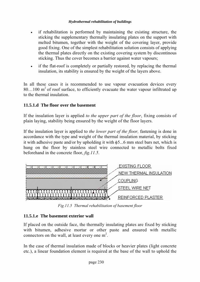
Hydrothermal rehabilitation of buildings
page 230
• if rehabilitation is performed by maintaining the existing structure, the sticking the supplementary thermally insulating plates on the support with melted bitumen, together with the weight of the covering layer, provide good fixing. One of the simplest rehabilitation solution consists of applying the thermal plates directly on the existing covering system by discontinous sticking. Thus the cover becomes a barrier against water vapours;
• if the flat-roof is completely or partially restored, by replacing the thermal insulation, its stability is ensured by the weight of the layers above.
In all these cases it is recommended to use vapour evacuation devices every 80…100 m2 of roof surface, to efficiently evacuate the water vapour infiltrated up to the thermal insulation. 11.5.1.d The floor over the basement If the insulation layer is applied to the upper part of the floor, fixing consists of plain laying, stability being ensured by the weight of the floor layers. If the insulation layer is applied to the lower part of the floor, fastening is done in accordance with the type and weight of the thermal insulation material, by sticking it with adhesive paste and/or by upholding it with φ5...6 mm steel bars net, which is hung on the floor by stainless steel wire connected to metallic bolts fixed beforehand in the concrete floor, fig.11.5.
Fig.11.5 Thermal rehabilitation of basement floor 11.5.1.e The basement exterior wall
If placed on the outside face, the thermally insulating plates are fixed by sticking with bitumen, adhesive mortar or other paste and ensured with metallic connectors on the wall, at least every one m2. In the case of thermal insulation made of blocks or heavier plates (light concrete etc.), a linear foundation element is required at the base of the wall to uphold the
Building Rehabilitation
page 231
weight of thermal insulation as well as that of the protection and finishing system.
From inside, the supplementary insulation is achieved by fixing the insulation plates with adhesive paste and/or with local metallic connectors, just like for the exterior walls. 11.5.2 The protection of the supplementary thermally insulating layer The protection systems of supplementary thermal insulation are different, depending on the element that will be rehabilitated, its surface position and the insulation type and structure. Theoretically, the protection of the supplementary thermal insulation of vertical elements may be achieved in two ways: with plaster or with plates, fig.11.6. 11.5.2.a Exterior walls In the case of supplementary thermal insulation on the inner face of the wall, the following solutions may be applied:
• reinforced plaster on steel net bars, fixed on the wall with stainless steel wire and connectors. To hinder water vapour infiltration in the rooms and to ensure the normal hygrothermal behaviour of the treated element it is absolutely necessary to have a vapour barrier made of bitumen cardboard or cloth, or plastics sheets, without holes and with well tighten joints, fig.11.7.a;
• washable tapestry with synthetic support, having high vapour tightness, applied by sticking with adhesive directly on the surface of supplementary thermally insulating plates, which has been rectified beforehand with gypsum-aracet layer or other adhesive paste, fig.11.7.b. This kind of finishing is very suitable in the case of additional thermal insulation made of expanded polystyrene plates;
• plates made of reinforced gypsum, industrial wood etc., whose surface is treated to act as a vapour barrier (by painting, lacquering, with tapestry etc.). They are fixed on the thermal insulation by sticking and ensured with mechanical devices, fig.11.7.c. This variant allows the prefabrication of the insulation-protection-finishing ensemble, with important advantages for the rehabilitation works.
If the supplementary thermal insulation is applied on the outer face of the exterior walls, the technical solutions for protecting the supplementary insulation layer may be the following:
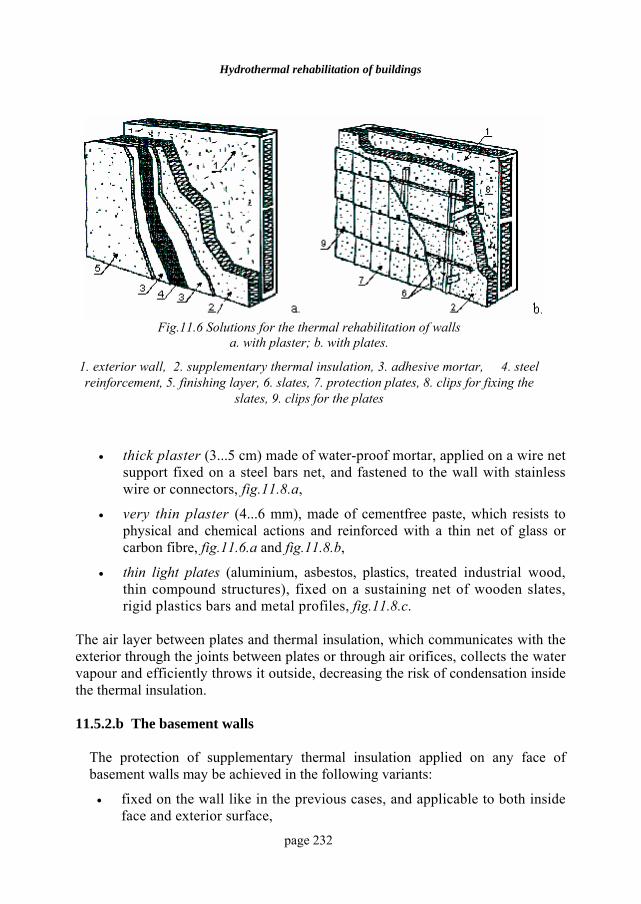
Hydrothermal rehabilitation of buildings
page 232
Fig.11.6 Solutions for the thermal rehabilitation of walls a. with plaster; b. with plates.
1. exterior wall, 2. supplementary thermal insulation, 3. adhesive mortar, 4. steel reinforcement, 5. finishing layer, 6. slates, 7. protection plates, 8. clips for fixing the
slates, 9. clips for the plates
• thick plaster (3...5 cm) made of water-proof mortar, applied on a wire net support fixed on a steel bars net, and fastened to the wall with stainless wire or connectors, fig.11.8.a,
• very thin plaster (4...6 mm), made of cementfree paste, which resists to physical and chemical actions and reinforced with a thin net of glass or carbon fibre, fig.11.6.a and fig.11.8.b,
• thin light plates (aluminium, asbestos, plastics, treated industrial wood, thin compound structures), fixed on a sustaining net of wooden slates, rigid plastics bars and metal profiles, fig.11.8.c.
The air layer between plates and thermal insulation, which communicates with the exterior through the joints between plates or through air orifices, collects the water vapour and efficiently throws it outside, decreasing the risk of condensation inside the thermal insulation. 11.5.2.b The basement walls
The protection of supplementary thermal insulation applied on any face of basement walls may be achieved in the following variants:
• fixed on the wall like in the previous cases, and applicable to both inside face and exterior surface,
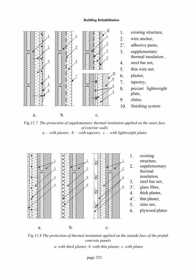
Building Rehabilitation
page 233
1. existing structure, 2. wire anchor, 2’. adhesive paste, 3. supplementary
thermal insulation , 4. steel bar net, 5. thin wire net, 6. plaster, 7. tapestry, 8. precast lightweight
plate, 9. slates,
65
4 7
3 3
3
3
2 2’2’
2’
9
8
1 1 1
10
10
10. finishing system
a. b. c. Fig.11.7 The protection of supplementary thermal insulation applied on the outer face
of exterior walls a. – with plaster, b. – with tapestry, c. – with lightweight plates
1. existing
structure, 2. supplementary
thermal insulation,
3. steel bar net, 3’. glass fiber, 4. thick plaster, 4’. thin plaster, 5. slate net,
3 53’
4 64’
2 22
1 11
6. plywood plates
a. b. c. Fig.11.8 The protection of thermal insulation applied on the outside face of the prefab
concrete panels a. with thick plaster, b. with thin plaster, c. with plates
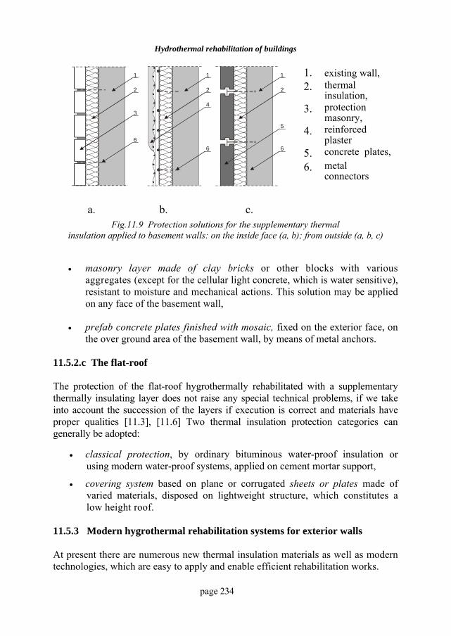
Hydrothermal rehabilitation of buildings
page 234
1. existing wall, 2. thermal
insulation, 3. protection
masonry, 4. reinforced
plaster 5. concrete plates,
34
5
66 6
2 2 2
1 1 1
6. metal connectors
a. b. c. Fig.11.9 Protection solutions for the supplementary thermal
insulation applied to basement walls: on the inside face (a, b); from outside (a, b, c)
• masonry layer made of clay bricks or other blocks with various aggregates (except for the cellular light concrete, which is water sensitive), resistant to moisture and mechanical actions. This solution may be applied on any face of the basement wall,
• prefab concrete plates finished with mosaic, fixed on the exterior face, on the over ground area of the basement wall, by means of metal anchors.
11.5.2.c The flat-roof The protection of the flat-roof hygrothermally rehabilitated with a supplementary thermally insulating layer does not raise any special technical problems, if we take into account the succession of the layers if execution is correct and materials have proper qualities [11.3], [11.6] Two thermal insulation protection categories can generally be adopted:
• classical protection, by ordinary bituminous water-proof insulation or using modern water-proof systems, applied on cement mortar support,
• covering system based on plane or corrugated sheets or plates made of varied materials, disposed on lightweight structure, which constitutes a low height roof.
11.5.3 Modern hygrothermal rehabilitation systems for exterior walls At present there are numerous new thermal insulation materials as well as modern technologies, which are easy to apply and enable efficient rehabilitation works.
Building Rehabilitation
page 235
In other countries, building rehabilitation is not an action of large proportions, since the initial execution of buildings has been based on high exigencies towards comfort requirements and the thermal insulation of closure elements. However, there are also many situations necessitating the modernization of old buildings. This is a good occasion to improve the thermal insulation performances of certain elements, exterior walls in particular. Rehabilitation works are usually performed on the exterior, avoiding the humid processes and following the well known principle: supplementary thermal insulation attached to the wall and protected by plates or thin plaster. Most systems use a net made of wood, metal profiles (steel, aluminium) or plastics, which ensure the fixing of the protective system usually at some distance from the thermal insulation to create a slightly ventilated air space. Protection by thick plaster is not usual but it has been applied and the variant with very thin plaster reinforced with thin carbon or glass fiber net is also used, fig.11.6.a and fig.11.8.b. Three of the most frequently used protection systems in several European countries will be presented below. Some of them have been applied experimentally in Romania as well. 11.5.3.a The LOBA system (VS, C-EL, M-EL, Mécanique) for thermal insulation on the façades of older buildings, without special finishing, is applied in Germany and France by the LOBA company, having the French technical agreement. This system is based on expanded polystyrene plates, whose thickness corresponds to insulation requirements. They are fixed on the outside surface of exterior masonry or concrete walls of the new or already existing buildings by means of an adhesive paste made of cement or polymeric resins. The protection of the thermal insulation consists of a thin cementfree paste with mineral components and synthetic binder or with cement and special polymeric additions, reinforced by a thin glass fiber net, with 3…4 mm mesh, protected against the alkalis.
11.5.3.b The ALUCOBOND system, attributed to the Swiss company ALUSUISSE, is different in the manner supplementary thermal insulation is achieved.
This solution consists of thermally insulating plates made of very efficient materials (polystyrene, polyurethane etc.), stuck directly to the exterior face of the wall and protected with plane or special panels made of a composite material called ALUCOBOND. This material consists of two 0.5 mm aluminium sheets glued on
Hydrothermal rehabilitation of buildings
page 236
the faces of a 2…7 mm polyethylene core. The outer face can be treated in various manners and colours. 11.5.3.c The POLYALPAN system, attributed to the German company with the same name differs from others in the protection of the thermally insulating layer applied on the wall by means of rigid polyurethane panels, which are finished on both faces with aluminium sheets. These panels, having special profiles on the long vertical sides, are easily fixed with nails on a wooden slates net against the wall, which also ensures the air space required to collect and eliminate the water vapour. 11.5.4 The economic effects of hygrothermal rehabilitation of buildings 11.5.4.a Energy savings due to thermal rehabilitation By applying some of the hygrothermal rehabilitation measures presented above (by supplementary insulation), room climate parameters may rise to a satisfactory level of comfort and energy is saved - two important advantages [11.4]. The annual net energy savings that can be obtained by improving the thermal insulation qualities of closure elements having the areas kS and whose initial
average overall thermal resistances kR ,0 have increased to 'k0,R may be
established with the relations:
( ) k,k,kt
k',k,k
t
SKKNr
E
SRR
NrlE
⋅′−⋅⋅=
⋅⎟⎟⎠
⎞⎜⎜⎝
⎛−⋅⋅=
∑
∑
00
00
1
11
(11.1)
where:
,kK0 and ,kK0′ are the average thermal transfer coefficients of the distinct zones with different envelope structure before and after rehabilitation,
,k,k KR 00 1= and ',k
',k KR 00 1= are the corresponding thermal resistances,
tN - the number of the degrees-hours for the locality the building is situated in. r – the efficiency of heating installations, thus:
r = 0,95 – heating by thermal station; r = 0,85 – heating by personal thermal installation;
Building Rehabilitation
page 237
r = 0,99 – electric heating; r = 0,65...0,85 – wood, coal or methane gas heating;
In order to evaluate the primary energy savings ( pE ) it is necessary to take into
account the efficiency of the distribution network ( dr ) as well as that of the thermal station ( cr ), so that:
Err
Ecd
p ⋅⋅=11 (11.2)
The values of the outputs (rc) and (rd) are found by using the data in the technical literature or the information provided by the producers. To evaluate energy savings, the average hygrothermal characteristics of the component elements of envelope ( kK , ,kR0 ) may be selected in the following way:
• for the opaque zone of exterior wall, whose overall surface area is ( 0pS )
and which consist of distinct zones with ( kS ) areas, having the thermal transfer coefficients ( kK ) – e.g. for the thermal bridge zone ( pS ) and
( pK ), for the connection zones ( iS ) and ( iK ), for the current zones ( cS )
and ( cK ) etc. – the average thermal transfer coefficient on the entire wall may be calculated as:
or:
∑∑
∑∑∑
===
==
kk
p
k
k
p
pp
p
kk
k
kkp
K.S
S
RS
SK
R
SS.K
S
S.KK
00
00
00
1 (11.3)
• for glazed zones, whose overall area is ( vS ), made of transparent zones with ( tvS , ) area and thermal transfer coefficient ( tvK , ), the thermal resistance ( tvR , ) respectively, as well as from the sum of the opaque zones (frames, jamb) with the overall area ( 0,vS ) and the thermal characteristics ( 0,vK ) and ( 0,vR )respectively, the flow of the air exchange between the joints after rehabilitation being ( aJ ), the average equivalent thermal
Hydrothermal rehabilitation of buildings
page 238
transfer coefficient is calculated with one of following relations:
aaav,
v,
v,t
v,t
v
vv
aaav,v,v,tv,tv
v
ρ.J.cRS
RS
SK
R
ρ.J.c)S.KS.(KS
K
++==
++⋅=
0
0
00
1
1
(11.4)
• for the flat-roof, with the overall area (St), which consists of zones of variable thickness, the average thermal transfer characteristics can be adopted considering average thickness values ( medkd , ) for the component variable layers, so that:
∑ ⋅++=
kk
k,med
eit λb
dαα
R 11
tt R
K 1=
(11.5)
• for the basement wall, with the overall over ground surface area ( sS ) and the average characteristics ( sK ) and ( sR ), calculus is done just like for the opaque zones of exterior walls of the building.
For the envelope elements or zones consisting of several layers of different materials, ( kd ) thick and having the thermal conductivity coefficients (λi) and quality coefficients ( kb ), the total thermal transfer resistance is the sum of thermal transfer resistances, using the equation:
ea,k
kk
k
i αR
λbd
αR 11
0 ++⋅
+= ∑∑
00
1R
K = (11.6)
where ( kaR , ) are resistances of air layers that may be in the structure of the envelope element to thermal permeability. These characteristics can be computed also using the initial values ( iR ,0 ), adding the supplementary thermal resistance of the rehabilitation layers (∆R):
Building Rehabilitation
page 239
∆RRR ,i += 00
00
1R
K = (11.7)
where:
iziz
iz,s
λbd
∆R⋅
= - for opaque zones,
∑= a,sR∆R - for glazed zones.
The annual net energy savings (E) may be also evaluated by means of the overall heat loss coefficient of the building ( G ), calculated for the initial state of the building ( 0G ) and after the execution of hygrothermal rehabilitation works ( rG ):
V)G(GNr
E rt ⋅−⋅⋅= 01 (11.8)
where the overall heat loss coefficient of the building (the total thermal insulation coefficient) G is calculated for the overall heat loss, from:
ncVS
RG a
M⋅+⋅=
0
1 (11.9)
where: MR ,0 is the average thermal resistance of the envelope,
n - the air exchange rate per hour of the building (h-1),
S - the total area of the building envelope (m2),
V - the interior volume of the building (m3),
ρ⋅= pa cc - the specific heat capacity of the air (W.h/m3K). 11.5.4.b The retrieve period of the investment in case of thermal rehabilitation In the case of the partial rehabilitation, the value of the total investment (I) needed for the hygrothermal rehabilitation of a building or of a building envelope element is established according to the current norms and estimated prices, considering all the expenses required by the execution of afferent works, less the finishing upkeep works in the ulterior exploitation period. The net energy savings obtained through rehabilitation can be evaluated with the relation:
Hydrothermal rehabilitation of buildings
page 240
pEE ⋅= (lei/an) (ROL/year) (11.10)
where: E is the annual net energy saved for that particular building as a consequence
of the application of thermal rehabilitation measures p – the cost of the net energy unit at the beneficiary (ROL/W.h), corresponding
to the heating type and to the valid prices at the time of execution. In order to evaluate the expenses retrieve period, the social expenses associated to the immobilized investment funds as well as the estimated future increase in energy cost need to be calculated. The following coefficients are thus established:
i - the updating coefficient of the investment funds (%); j - the coefficient of the annual increase in energy price (%),
depending on price policy and the fuel utilized. The updating coefficient of the investment funds (Y) is expressed by:
)1(/)( jjiY +−= (11.11) The retrieve standing (in years) of the investment for the thermal rehabilitation of a building (n) may be calculated using the relation:
)1(lnln YYR
Rn +−
= (11.12)
where: R - is the ratio between the estimated annual energy savings and the investment value:
EER /= (11.13) BIBLIOGRAPHY 11.1 Bliuc, I., Elemente de fizica construcţiilor, Tipar Rotaprint, I.P. Iaşi,
1993. 11.2 Gavrilaş, I., Fizica construcţiilor. Reabilitarea higrotermică a clădirilor.
Editura Cermi, Iaşi, 1999. 11.3 Gavrilaş, I., Reabilitarea acoperişurilor clădirilor civile, Editura Cermi,
Iaşi, 2000. 11.4 Velicu, C. (coordonator), Protecţia termică a clădirilor. Elemente de
specializare, Editura Experţilor Tehnici, Iaşi, 1998. 11.5 * * *, STAS 6472/3-89, Fizica construcţiilor. Termotehnica. Calculul

Building Rehabilitation
page 241
termotehnic al elementelor de construcţii ale clădirilor, IRS, Bucureşti, 1989.
11.6 * * *, Volumul Simpozionului „Reabilitarea termică a clădirilor”, Iaşi, 1996.
CCColectia: CONSTRUCTII CIVILE ISBN 973-7962-26-5